
BINARIO TRIFASE art. 7511 440V 16A CL1
Il binario ed i suoi componenti, compresi gli adattatori in CI 1 non sono intercambiabili con
sistemi a binario di classe III o con accessori che non riportino il Marchio di Qualità.
E’ responsabilità dell’utente assicurare la compatibilità elettrica, meccanica e termica tra i
sistemi a binario e gli apparecchi ad esso connessi.
Montaggio
Installare il bianario tramite i fori già predisposti sul profilato oppure utilizzando gli accessori art.
7606 - Kit di sospensione oppure art. 7607 - Kit soffitto, coi limiti di carico indicati nella fig. 5.
Connettori di alimentazione art. 7652 Dx art. 7652 Sx 440V 16A
Collegamento:
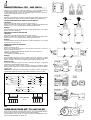
Aprire il vano portacontatti, svitando le due viti come indicato nella fig. 2.
Sfondare la prerottura per il passaggio del cavo, collegare i conduttori facendo attenzione alla
dicitura N L1 L2 L3 T e successivamente bloccarli tramite il ponticello fermacavo.
Montaggio:
Inserire il connettore nel binario facendo attenzione al corretto orientamento (Dx o Sx) e quindi
bloccarlo con la vite A come da fig. 2.
Alimentazione centrale art. 7653 440V 16A
Collegamento:
Aprire il vano portacontatti svitando le quattro viti come indicato in fig. 3.
Sfondare la prerottura per il passaggio del cavo, collegare i conduttori facendo attenzione alla
dicitura N L1 L2 L3 T e successivamente bloccarli tramite il ponticello fermacavo.
Montaggio:
Inserire il connettore nel binario facendo attenzione al corretto orientamento (Dx o Sx) e quindi
bloccarlo con le viti A come da fig. 3.
Adattatore per binario art. 7601 250V 6A
Collegamento:
Svitare le tre viti come da fig. 4A
Inserire il cavo dell’apparecchio attraverso il foro della bussola di rotazione e fissarlo con
l’apposito ponticello come da fig. 4D
Collegare i tre conduttori facendo attenzione alla dicitura L N T come da fig. 4B e 4C-
Rimontare e fissare il coperchio.
L’uso è limitato al sistema binario specificato
Montaggio:
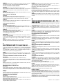
Inserire l’adattatore nel binario con la leva D orientata come da fig. 6 posizione F e quindi
bloccarlo ruotandola dalla posizione F alla posizione G. Selezionare quindi la fase desiderata
tramite la manopola E come da fig. 6. Non applicare apparecchi di peso superiore a 50N.
Montaggio a parete
Nel caso del montaggio a parete con binario in posizione orizzontale, non applicare
all’adattatore un momento flettente superiore ad 1Nm
Nel caso di montaggio a parete con binario in posizione verticale, la scanalatura di guida del
profilato del binario deve essere a destra; non applicare all’adattatore un momento flettente
superiore a 2Nm.
Attenzione! Per l’installazione di faretti aventi un peso superiore a 50N o che superano i
momenti flettenti rispettivamente di 1Nm e 2Nm, utilizzare l’adattatore meccanico art. 7625.
UK
THREE-PHASE TRACK ART. 7511 440V 16A CL1
The track and its components, including adapters in Class I, are not interchangeable with track
systems in Class III or with accessories which do not show the Quality Mark.
The responsibility to ensure the electric, mechanical and termic compatibility between track
systems and connected fittings rests with the user.
FIG. 1
FIG 2
FIG 3
FIG 4A
FIG 4B
FIG 4C
FIG 6
FIG 4D
F
E
GD
AA
}
16A
16A
N
L1
L2
L3
16A
AUTOMAT
N
L
16A N
L1
L2
L3
N
L1
L2
L3
max
16A
16A
16A
200 200 200 200
2 kg 2 kg 2 kg 2 kg 2 kg
800
200 200 200 200
10 kg 10 kg 10 kg 10 kg 10 kg
400 400
16A
N
L1
N
L
16A
Automat
SCHEMA ELETTRICO
CARICO MASSIMO
FIG. 5
DX
SX
FIG. 2
AA
DESTRO
RIGHT
SINISTRO
LEFT
max 0,25 N/m max 0,25 N/m

Installation
Install the track by the holes on its surface or by using the accessories art. 7606 -
suspension kit, or art. 7607 - ceiling kit, respecting the load limits shown in pic. 5.
Live-ends art. 7652 Dx art. 7652 Sx 440V 16A
Connection:
Open the case with contacts by unscrewing the two screws as in pic. 2.
Break the bottom of the suitable hole to let the cable pass through. Connect the wires
paying attention to the caption N L1 L2 L3 T and then fix them by the strain relief.
Installation:
Insert the live-end into the track, paying attention to the right orientation (Dx or Sx) and
then fix it by the screw A, as in pic. 2.
Mean connector art. 7653 440V 16A
Connection:
Open the case with contacts by unscrewing the four screws as in pic. 3.
Break the bottom of the suitable hole to let the cable pass through. Connect the wires
paying attention to the caption N L1 L2 L3 T and then fix them by the strain relief.
Installation:
Insert the connector into the track, paying attention to the right orientation (Dx or Sx)
and then fix it by the screws A as in pic. 3.
Track adapter art. 7601 250V 6A
Connection:
Unscrew the three screws as in pic. 4A.
Insert the cable of the fitting into the rotation washer and fix it by the suitable device, as
in pic. 4D. Connect the three wires paying attention to the caption L N T , as in pic. 4B
and 4C. - The use is limited to specified rail system
Installation:
Insert the adapter into the track with the lever D oriented as in pic. 6, position F, and
then fix it turning it from the position F to the position G.
Select the phase you wish by using the handgrip E, as in pic. 6.
Do not install fittings with load over 50 N .
Wall mounting
In case of wall mounting with track in horizontal position, do not apply a moment of
flexure over 1 Nm to the adapter.
In case of wall mounting with track in vertical position, the guide groove of the track
surface must be on the right. Do not apply a moment of flexure over 2 Nm to the
adapter.
Warning! To install fittings weighing over 50 N, or exceeding the moments of flexure of
respectively 1 Nm and 2 Nm use the mechanical adapter art. 7625.
F
RAIL TRIPHASE’ ART. 7511 440V 16A CL1
Le rail et ses composants, inclus les adaptateurs en CI. I ne sont pas interchangeables
avec des systèmes rail en CI. III ou avec des accessoires qui n’ont pas le Marquage de
Qualité.
C’est résponsabilité de l’utilisateur assûrer la compatibilité électrique, mécanique et
thermique entre les systèmes rail et les appareils branchés.
Montage
Installer le rail par les trous présents sur le profilé ou utilisant les accessoires art. 7606 -
kit suspension, ou art. 7607 - kit plafond, avec les limites de charge indiquées dans la
fig. 5.
Connecteurs d’alimentation art. 7652 Dx art. 7652 Sx 440V 16A
Branchement:
Ouvrir le boîtier des contacts, dévissant les deux vis comme dans la fig. 2.
Percer la pre-ouverture prévue pour le passage du câble; brancher les conducteurs,
faisant attention à la légende N L1 L2 L3 T et successivement les fixer par le dispositif
serre-câble.
Montage:
Insérer le connecteur dans le rail faisant attention à l’orientation correcte (Dx ou Sx);
après le fixer par la vis A comme dans la fig. 2.
Alimentation médiane art. 7653 440 V 16A
Branchement:
Ouvrir le bôitier des contacts, dévissant les quatre vis comme dans la fig. 3.
Percer la pre-ouverture prévue pour le passage du câble, brancher les conducteurs,
faisant attention à la légende N L1 L2 L3 T et successivement les fixer par le dispositif
serre-câble.
Montage:
Insérer le connecteur dans le rail, faisant attention à l’orientation correcte (Dx ou Sx) et
après le fixer par les vis A comme dans la fig. 3.
Adaptateur pour rail art. 7601 250V 6A
Branchement:
Dévisser les trois vis comme dans la fig. 4A.
Insérer le câble de l’appareil dans le trou de la douille de rotation et le fixer par le
dispositif correspondant, comme dans la fig. 4D.
Brancher les trois conducteurs faisant attention à la légende L N T comme dans la fig.
4B et 4C.Remonter et fixer le couvercle.
L’emploi est limité au systéme rail spécìfié
Montage:
Insérer l’adaptateur dans le rail avec le levier D orienté comme dans la fig. 6, position F,
et après le fixer par la rotation de la position F à la position G.
Après sélectionner la phase désirée par la poignée E, comme dans la fig. 6.
N’installez pas d’appareils de poids supérieur à 50 N.
Montage à mur
En case de montage à mur avec le rail en position horizontale, n’appliquez pas à
l’adaptateur un moment de flexion supèrieur à 1 Nm.
En cas de montage à mur avec le rail en position verticale, la rainure de guide du profilé
du rail doit être à droite; n’appliquez pas à l’adaptateur un moment de flexion supérieur
à 2 Nm.
Attention! Pour l’installation de spots de poids supérieur à 50 N, ou dépassant les
moments de flexion respectivement de 1 Nm et 2 Nm, employer l’adaptateur mécanique
art. 7625.
D
DREIPHASENSTROMSCHIENE ART. 7511
440V 16A CL1
Die Stromschiene und ihre Komponenten, inbegriffen die Adapter in Kl I, sind nicht
auswechselbar mit Stromschienesysteme in KI. III oder mit Zubehören, die kein
Qualitätzeichen zeigen.
Der Benutzer ist dafür verantwortlich, die elektrische, mechanische und thermische
Kompatibilität zwischen den Stromschienesystemen und den verbundenen Strahlern zu
sichern.
Montage
Installieren Sie die Stromschiene durch die auf dem Profil vorgebohrten Löcher, oder
benutzen Sie die Zubehöre Art. 7606 - Stahlseil-Abhänger oder Art. 7606 - Kit für
Decke, indem Sie die Ladengrenzen wie aus Bild 5 beachten.
Einspeisungsstücke art. 7652 Sx 440V 16A
Verbindung:
Öffnen Sie das Kontaktsgehäuse, indem Sie die zwei Schrauben wie im Bild
2 abschrauben.
Schlagen Sie den Boden der vorbereiteten Öffnung aus, um das Kabel durchzuziehen;
verbinden Sie die Leitungen, indem Sie auf die Aufschrift N L1 L2 L3 T achtgeben.
Dann befestigen Sie sie durch die Klemme.
Montage:
Stecken Sie das Einspeisungsstück in die Stromschiene, indem Sie auf die richtige
Orientierung (Dx oder Sx) achtgeben, und dann befestigen Sie es mit der Schraube A
wie aus Bild 2.
Mittleres Einspeisungsstück Art. 7653 440V 16A
Verbindung:
Öffnen Sie das Kontaktsgehäuse, indem sie die vier Schrauben wie aus Bild
3 abschrauben.
Schlagen Sie den Boden der vorbereiteten Öffnung aus, um das Kabel durchzuziehen;
verbinden Sie die Leitungen, indem Sie auf die Aufschrift N L1 L2 L3 T achtgeben, und
dann befestigen Sie sie mit der Klemme.
Montage:
Stecken Sie das Einspeisungsstück in die Stromschiene, indem Sie auf die richtige
Orientierung (Dx oder Sx) achtgeben, und dann befestigen Sie es mit den Schrauben A
wie aus Bild 3.
Steckadapter Art. 7601 250V 6A
Verbindung:
Schrauben Sie die drei Schrauben wie aus Bild 4A ab. Stecken Sie das Kabel des
Strahlers ins Loch der Büchse und befestigen Sie es mit der besonderen Vorrichtung
wie aus Bild 4D. Verbinden Sie die drei Leitungen, indem Sie auf die Aufschrift L N T
wie aus Bild 4B und 4C achtgeben.
Legen Sie die Decke wieder auf und befestigen Sie sie.
Die Benutzung wird zurn angegebenen Schienensystem eingeschränkt
Montage:
Stecken Sie den Adapter in die Stromschiene mit dem Hebel D wie aus Bild 6, Lage F,
gerichtet, dann befestigen Sie ihn, indem Sie den Hebel von der Lage F zur Lage G
drehen.
Dann wählen Sie die gewünschte Phase durch den Griff E wie aus Bild 6 aus.
Installieren Sie keine Strahler mit einem Gewicht größer als 50 N.
Montage an der Wand
Wenn Sie die Stromschiene horizontal an die Wand installieren, legen Sie dem Adapter
ein Moment von Biegung nicht größer als 1 Nm an.
Wenn Sie die Stromschiene senkrecht an die Wand installieren, muß die Führungsnut
des Profils der Stromschiene rechts sein: legen Sie dem Adapter ein Moment von
Biegung nicht größer als 2 Nm an.
Achtung! Benutzen sie den mechanischen Adapter Art. 7625, um Strahler mit einem
Gewicht größer als 50 N zu installieren, oder wenn sie die Momente von Biegung
beziehungsweise von 1 Nm und 2 Nm übersteigen.
99-06040-31 – LT 183 –
01/03/2001
-
 1
1
-
 2
2


Deko-light 555210 Manuale del proprietario
- Tipo
- Manuale del proprietario
- Questo manuale è adatto anche per
in altre lingue
- English: Deko-light 555210 Owner's manual
- français: Deko-light 555210 Le manuel du propriétaire
- Deutsch: Deko-light 555210 Bedienungsanleitung


