Lanzar OPTI 200X4 Manuale utente
- Categoria
- Set di altoparlanti
- Tipo
- Manuale utente

pt

« »
ti
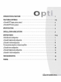
INTRODUCTION
&
FEATURES
.................................................
p
...................
1
FEATURES
&
CONTROLS
.......................................................................................
2-3
2 Channel(OPTI 250X2,
500X2,
700X2)
............................................................................
2
4
Channel(OPTI
2oox4,
250X4)
.....................................................................................
3
SPECIFICATIONS
.................................................................................................
4
INSTALLATION
&
PRECAUTIONS
.......................................................
. . . . . . . . . . . . . . . . . . .. 5
SYSTEM
WIRING··
.
...
.
...
.
...
.
...
.
.... .... .... .... .... ....
.
...
.
...
.
...
.
...
.
...
.
...
.
...
.
...
.
...
.
...
.
.... .... ....
..
6-12
2
Channel
stereo
configuration
......................................................................................
7
2
Channel
bridged
mode
configuration
.............................................................................
7
2
Channel
tri-mode
configuration
. . . . . . . . . . . . . . . . . . . . . . . . . . . . . . . . . . . . . . . . . . . . . . . . . . . . . . . . . . . . . . . . . . . . . . . . . . . . . . . .. 8
Tri-amp
system
using
three
2
Channel
amplifiers
................................................................
9
4
Channel
stereo
configuration
.....................................................................................
10
4
Channel
bridged
mode
configuration
...
. . . . . . . . . . . . . . . . . . . . . . . . . . . . . . . . . . . . . . . . . . . . . . . . . . . . . . . . . . . . . . . . . . . . . . . ..
11
4
Channel
tri-mode
configuration
.................................................................................
12
TROUBLESHOOTING
. . . . . . . . . . . . . . . . . . . . . . . . . . . . . . . . . . . . . . . . . . . . . . . . . . . . . . . . . . . . . . . . . . . . . . . . . . . . . . . . . . . . . . . . . ..
13
WIRING
.............................................................................................................
14
olatlZQl'
O~TI
oWn!!!
....
!5
mAnUAL

411
.....
~
P
-
Congratulations
on
your
purchase
of
a Lanzar OPT! amplifier. You have
purchased
a
quality
product
designed
and
engineered
to
give you
many
years
of
uncompromised
musical service. OPT! amplifiers
are
designed
with
the
latest
technology available,
incorporating
a
DC
to
DC
Switching Power Supply, which provides
headroom
for
even
the
most
demanding
peaks
and
dynamic
ranges
found
on
modern
CD's
and
recordings.
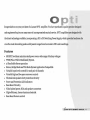
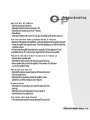
Features
• MOSFET switches
maintain
rated
power
over a wide
range
of
battery
voltages
• PWM(Pulse-Width-Modulated) System.
• 2
Ohm
Stable
Stereo
operation
• Stereo, Bridge Mode
and
Tri-Mode System Application Compatible
• Variable
input
level
controls
for
each
pair
of
channels
• Variable
high
and
low
pass
crossover
controls
•
Thermal
and
speaker
short
protection
circuitry
• Power
and
Protection
LED
indicators
• Bass Boost Circuitry
• Nickel
plated
power,
RCA
and
speaker
connectors
• High-efficiency, heavy
aluminum
heatsink
• Bass Boost Remote
control
ofanzal'
OPTI
OWnIiiFf5i
mAnUAL
- ,

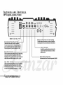
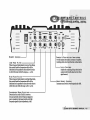
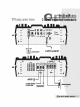
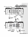
FEATURES
AND
CONTROLS
OP'n
250X2,
500X2,
700X2
Remote
High
aero
..
over
Pa
••
'9
-
:.~
Flat.J I L.
a.-
••
• •
::=
.....
so
7_
REMOTE
CONTROL
CROSSOVER
MODE
SELECTOR-------'
Deternrines
the
mode
of
built-in crossover:
low pass (permits only low frequency signals
to
pass
to
speakers), high pass (permits only high
frequency signals
to
pass
to
speakers),
or
flat.
HIGH
PASS
FILTER
--------------1
When
Crossover Mode Selector is
in
High Pass Mode,
this control limits
the
frequencies which will
be
distributed
to
the
speakers
to
those above
the
value
to
which this is
set
within
the
range
50Hz-750Hz.
Low
Pa
••
...
•••
. .
• •
••
..
,
..
Low
PASS
FI
L
TE
R
---------------....1
When Crossover Mode Selector is
in
Low Pass Mode,
this control limits
the
frequencies which will
be
distributed to
the
speakers to those below
the
value
to
which this
is
set
within
the
range
50-
120Hz
.
.J!andJi'
O
..
TI
ownl!!
.... !5
IlIAnUAL
- i!!
oI..anzar
OPTI
ownEFI
5
mAnUAL
B
•••
Boost
Level
.
..
.
..
•••
•••
. . . .
• • • •
• • • •
...
tad.
III..
.....
Input
Line
out
@ @
-,
L
P ctuetiuiii
0
0 0
R
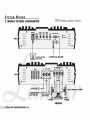
POWER
&
PROTECTION
INDICATORS
~deinstantllrlOrmationonstatusofamplifier,
including short-circuit
and
thermal
overload alerts.
'-----
LEVEL
CONTROL
Enables
the
matching
of
input
levels
to
the
output
levels from
the
head
unit
(or
other
signal
source).
'-------
BASS
BOOST
CONTROL
Increases sound level
in
lower frequencies
by
l8dB.

Low
1m
......
, ' .
@
'
•.
. .
, .
• •
o
&0
120
~
·:e:
Remote
• •
0
Ch2
..
...
REMOTE
CONTROL------~
Low
PAS
S F I L T E R
------------------1
When Crossover Mode Selector
is
in Low Pass Mode,
this control limits the frequencies which will be
distributed to the speakers to those below the value
to which
this
is
set within the range
50-
120Hz.
High
......
,
..
'
•.
. .
• •
' .
..
,
..
'
..
'
•.
. .
• •
' .
so
,
..
H I G H
PAS
S F I L T E R
-------------------------'
When Crossover Mode Selector
is
in High Pass Mode,
this control limits the frequencies which will be
distributed to the speakers to those above the value to
which this is set within the range
50Hz-750Hz.
Crossover
~~
~~
FI.t
""-
=~
~~
FI.t
....
C R 0 S S 0 V E R
MOD
ESE
L E C
TOR
-----------------------'
Detenrunes the mode of built -in crossover:
low pass
(pennits only low frequency signals to
pass to speakers), high pass (permits only high
frequency signals to pass
to
speakers),
or
flat.
,
..
'
•.
. .
, .
• •
...B ,
....
Input
Ch.
Ch3
,
..
-..
'
•.
@
. .
• •
Prvtectlon
' .
Min
M
..
0
·:e
~
~
' .
Min
M_
Ch2
0
POWER
&
PROTECTION
INDICATORS
Provide instant information on status of amplifier,
including short-circuit and thermal overload alerts.
LEVEL
CONTROL
Enables the matching
of
input levels to the
output levels from the head unit (or other
signal source).
L...------BASS
BOOST
CONTROL
Increases
sound
level
in lower frequencies
by
18dB.
ofanztU'
OPTI
ownER's
ml'lnul'lL. - a

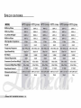
SPECIFICATIONS
MODEL
OPT! 250X2
OPTI
500X2
OPT!700X2
OPTIlOox4
OPT! 200X4 OPT! 250X4
RMS
at4
Ohms
250Wx2
500Wx2
700Wx2
100Wx4 125Wx4
250Wx4
MAXat40hms
5OOWx2
1000Wx2 1400Wx2
200Wx4
4OOWx4 5OOWx4
At
4
Ohms
Bridged
l()()()W
x 1
200OWx1 28OOWx1
400Wx2
BOOWx2
1000Wx2
RMS
at
2
Ohms
350Wx2
750Wx2
1050Wx2
150Wx4
200W
x4
350Wx4
Min.
Speaker
Impedance
2 Ohm 2 Ohm 2 Ohm 2 Ohm 2 Ohm 2 Ohm
T.H.D
0.04 % 0.04 % 0.04 % 0.04 % 0.04 % 0.04 %
Frequency
Response
10Hz-35Khz,-ldB 10Hz-35Khz,-ldB 10Hz-35Khz,-ldB 10Hz-35Khz,-ldB 10Hz-35Khz,-ldB 10Hz-35Khz,-ldB
Input
Sensitivity
200mV-BV 20OmV-BV 200mV-BV 20OmV-BV 200mV-BV 20OmV-BV
SjNRatio
>l00dB >l00dB >l00dB >l00dB >l00dB >100dB
Channel
Separation
>6OdB
>60dB
>6OdB
>60dB
>6OdB
>60dB
Crossover
(Low
Pass
Filter)
SOHz-120Hz
50Hz-120Hz
SOHz-120Hz
50Hz-120Hz
SOHz-l20Hz
50Hz-120Hz
Crossover(High
Pass
Filter)
SOHz-7SOHz
50Hz-750Hz
SOHz-7SOHz
50Hz-750Hz
SOHz-7SOHz
50Hz-750Hz
Bass
Boost
Control
o--+lBdB O-+lBdB o--+l8dB O-+lBdB o--+l8dB O-+lBdB
Dimensions(inches)
10.OS"x2.12"xlB.SO" lO.08"x2.12"x23.22" 11.42"x2.68"x23.68" lO.08"x2.12"xlS.7S" lO.08"x2.12"x16.73" 11.42"x2.68"x21.65"
Fuse(s)
25Ax4
4OAx4
Non
30Ax3 30Ax3
Non
.i!anzaI'
O
..
TI
ownl!!
.... !5
mAnUAL
-
..

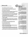
INSTALLATION
......
»
PRE
-
1. Find a suitable location in the vehicle to mount the amplifier.
2.
Make sure there is sufficient air
flow
around the intended mounting location.
3.
Bolt the amplifier to the mounting surface.
4.
Counect the power ground terminal to the nearest point on the
cl1assis
of the car.
Keep
this ground wire less than one meter (39") in length. Use 8 gauge wire.
5.
Counect the remote terminal to the remote output
of
the head unit using
14
gauge wire.
6. Counect
an
empty fuse holder within
300
mm
(12")
of
the battery and run 8 gauge
or
larger high quality cable from this fuse to the amplifier location.
7.
Make sure there is no fuse in this fuse holder. Then make the connection to the
"BATf"
connection on the amplifier.
8.
If
multiple amplifiers are being used, use cables (eacll with its own fuse at the battery)
or a
#0
or
#2
cable from the fuse holder at the battery to a distribution block at or near
the amplifier's location.
9. Connect all line inputs and outputs using high-quality
RCA-RCA
cables.
10.
Iusert fuse(s) at the batteryfuseholder(s).
11. Recheck all connectious before powering up.
12.
Set all level controls to their least sensitive positions and set all crossover controls,
switcl1es,
etc. to the desired frequency or position.
13.
Once the system is powered up, set the volume control on the head unit to about the
2 o'clock position, and then set all the amplifiers'level controls for maximum output
level.
14.
Further fine tuning of the various controls may
be
necessary to obtain the desired results.
•
Before
you
drill or
cut
any
holes,
investigate
your
car's
layout
veIY
carefully.
Take
care
when
you
work
near the
gas
tank,
fuel
lines,
hydraulic lines and
electrical
wiring.
• Do
not
operate
the
amplifier
when
it
is
unmounted.
Attach all
audio
system
components
securelywithin
the
automobile
to
prevent
damage,
especially
in
an
accident.
•
Do
not mount this amplifier
so
that the
wire
connections are unprotected or in a pinched
condition,
or likely
to
be
damaged
by
nearby
objects.
Be
sure
to
select
a
location
inside
your
vehicle
which
has adequate
ventilation.
•
Before
making or
breaking
power
connections
in
your
system,
disconnect
the
vehicle
battery.
Confirm
that
your
head unit or other equipment
is
turned
off
wbile
connecting the input jacks and speaker
terminals.
•
If
you
need
to
replace
the
power
fuse,
only
replace
it with a
fuse
identical
to
that supplied
with
the
system.
Using
a
fuse
of a different
type
or rating
may
resnlt
in
damage
to
your
system
which
isn't
covered by the manufacturer's warranty.
ofanzal'
OPTI
ownliR'5O
ml'lnul'lL.
- Iii

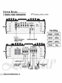
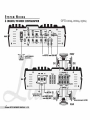
SYSTEM
WIRING
2 CHANNEL STEREO CONFIGURATION
OPTI250X2,500X2,700X2
FRONT
=
o
=
REAR
0 =
High
Low
a._
;;;;;;;;
c:
..... _
..... .....
Boo.,
.......
Inpllt
Lin.
out
-
:e"
""~
:e"""~ :e""·~
:e"··~
0-,
0--
...,....J
I
La.-
'.
.-
'.
.-
'.
.-
'.
.-
;::'--.,.
M
120
_ ,
.........
_
to
REMOTE
SUBWOOFER
LEVEL
CONTROL
TO
OUTPUT
FROM
HEAD
UNIT
B+
REII GND
TO
BATTERY
®
_---I
TO
REMOTE
OUTPUT
---..I
FROM
HEAD
UNIT
CHASSIS
GROUND
(BARE
METAL)
LEFT
RIGHT
SPEAKER
SPEAKER
.i!anzaI'
O
..
TI
ownl!!
.... !5
mAnUAL
- iii
=
o
=
= 0
SPEAKER IMPEDANCE
2-4
OHM
Fuse
Rating
Model
FUSES
250X2
2sAx4
500X2
4oAx4
700X2
Non

OPTI2S0X2,SOOX2,700X2
2
=
FRONT
0 =
High Low
....
;;;;;;'c
......
ov..
PII..
Pa..
Boo.I
Level
-
:".-
-~
:.~ :.~ :.~
.....-J I
L~',
.-
"
.-
"
.-
"
.-
~""'''7M'''H''1'''
••
I.''''
to
REMOTE
SUBWOOFER
lRIEL
CONTROL
F._
B+
REM
"ND
Input
Lin.
out
0-
o
P..e.c:t""
TO
OUTPUT
FROM
HEAD
UNIT
I
+
=
= 0
=
mmmm
0
REAR
=
0
=
TO
BATTERY
®
TO
REMOTE OUTPUT
FROM
HEAD
UNIT
0
-
CHASSIS GROUND
(BARE METAL)
SPEAKER
IMPEDANCE
4-8
OHM
ofanzal"
OPTI
ownliR"5O
ml'lnul'lL.
- ,

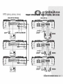
SYSTEM
WIRING
2 CHANNEL TRI-MODE CONFIGURATION
OPTI250X2,500X2,700X2
FRONT
=
o
=
REAR
0 =
.i!anzaI'
O
..
TI
ownl!!
.... !5
mAnUAL
-
II
::
=:c,
....
,
....
High Low B
...
Pa.. Pa..
Boost
Level
Inp
.. t Lin. out
-
.•.....•.....•......•...
.
..
..
..
.
..
..,.JHI..,L=
'.
.-
'.
.-
'.
.-
'.
.-
P8H
..
'
....
120_1
.......
_
0-,
0-
to
REMOTE
SUBWOOFER
LEVEL
CONTROL
TO
OUTPUT
fROM
HEAD
UNIT
B+
REM
GND
TO
BAmRY
®
_---I
TO
REMOTE
OUTPUT
"""':~=~
fROM
HEAD
UNIT
CHASSIS
GROUND
(BARE
METAL)
SUBWOOFER
=
o
SPEAKER IMPEDANCE 4-8
OHM

OPTI
250X2,
500X2,
700X2
o~
0-
MAsTER
AMp
FRONT (WOOFERS)
TO
OUTPUT
FROM
HEAD
UNIT
Sw:ltdlln _
[.o",ru.
RtoIf-I
I
Lt.-
Poaition
::::
_
SWitchin
flItPChlltton
Swtteh
in
Hllhp
....
Pglitiou
- 0
TRIAMP
0-
0-
o
o
~
NEL
AMPLIFIERS
MAsTER
AMp
REAR
......
II
TO.."...®
TO
RfMOTE
0UTl'UT
PIIOM
HfAD
UNIT
TO
"""""
00-...1
TO
IIfMOTI!
CJU11'\IT
__
.J
PIIOM
HEAD
UNIT
WOOFERS
-
MIDRANGE
TWEETERS
ofallZlll
CPTI
CWn.FI'Iii
ml'lnUI'lL.
-
II

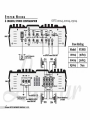
SYSTEM
WIRING
4 CHANNEL STEREO CONFIGURATION
FRONT
=
0 =
=
REAR
=
o
High Crossover
Po
••
••••••
. .
'.
•• !-"':!:""
•••
to
REMOTE
SUBWOOFER
LEVEL
CONTROL
CHASSIS
GROUND
(BARE
METAL)
BAmRY
®
REMOTE
OUTPUT
FROM
HEAD
UNIT
.Lanza#'
OPTI
ownER's
mAnUAL
-
10
= 0
SPEAKER IMPEDANCE
2-4
OHM
Fuse
Rating
Model
FUSES
loox4
30Axa
2oox4
3oAx3
250X4
Non

FRONT
=
o
=
REAR
=
0 =
••••••
. .
. .
..
Ch2
'"
120
'ii2
High
Pa
..
••••••
. .
. .
..
to
REMOTE
SUBWOOFER
LEVEL
CONTROL
o
TO
FRONT
OUTPUT
FROM
HEAD
UNIT
Fu
•••
CHASSIS
GROUND
(BARE
METAL)
BATTERY
@
REMOTE
OUTPUT
FROM
HEAD
UNIT
FRONT
REAR
STEM
WIRING
."u
,ll:.u-muDE CONFIGURATION
TOREAROUTPUT
FROM
HEAD
UNIT
=
=
= 0
SPEAKER IMPEDANCE
4-8
OHM
ofanztU"
OPTI
ownER's
ml'lnul'lL.
-
11

SYSTEM
WIRING
4 CHANNEL TRI-MODE CONFIGURATION
FRONT
=
0 =
••••••
. .
. .
..
-
,.
CO2
""in
High C
....
....,.r
Pas •
••••••
. .
0
••
-
~r::""-
to
REMOlE
SUBWOOFER
LBlEL
CONTROL
CHl
GND
REM
B+
Fu
...
=
REAR
=
o
.Lanza#'
OPTI
ownEFl"s
mAnUAL
-
12
o
o
!o......-.r--'T"'""""T""
......
CHASSIS
GROUND
(BARE
METAL)
BATTERY
®
REMOTE
OUTPUT
FROM
HEAD
UNIT
CH3
OPTll00X4,
200x4,
250X4
= 0
FRONT
=
=
o
CH4
SPEAKER IMPEDANCE
4-8
OHM
REAR

AMPLIFIER
WILL
NOT
POWER
UP.
• Check for good
ground
connection.
• Check
that
remote
DC
terminal
has
at
least
3v
DC.
• Check
that
there
is battery power
on
the
+ terminal.
• Check
all
fuses.
• Check
that
Protection LED is
not
lit.
If
it
is lit,
shut
off amplifier briefly
and
then
repower it.
HIGH
HISS
OR
ENGINE
NOISE
(ALTERNATOR
WHINE)
IN
SPEAKERS.
• Disconnect
all
RCA
inputs to
the
amplifier(s) - ifhiss/noise disappears, then plug
in
the
component
driving
the
amplifier
and
unplug its inputs.
Ifhiss/noise
disappears, go
on
until
the
faulty/noisy
component is found.
•
It
is
best
to
set
the
amplifier's
input
level as low as possible.
The
best
subjective
SIN
ratio
is obtainable
this way.
Try
to
drive as high a signal level from
the
head
unit
as possible.
PROTECTION
LED
COMES
ON
WHEN
THE
AMPLIFIER
IS
POWERED
UP.
• Check for shorts
on
speaker leads.
• Check
that
the
volume control
on
the
head
unit
is turned down low.
• Remove speaker leads,
and
reset
the
amplifier.
If
the
Protection LED still comes
on,
then
the
amplifier is faulty.
AMPLIFIER(S)
GETS
VERY
HOT.
• Check
that
the
minimum
speaker impedance for
that
model is correct.
• Check for speaker shorts.
• Check
that
there
is good airflow
around
the
amplifier.
In
some
applications,
an
external cooling fan
may
be
required.
DISTORTED
SOUND
• Check
that
the
Level
control(s) is
set
to
match
the
signal level
of
the
head
unit.
• Check
that
all
crossover frequencies have
been
properly set.
• Check for shorts
on
the
speaker leads.
HIGH
SQUEAL
NOISE
FROM
SPEAKERS.
• This is almost always caused by a poorly-grounded
RCA
patch
cord.
ofanzal'
OPTI
ownliR'5O
ml'lnul'lL.
-
1i1

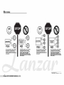
WIRING
©
2-channa'
Amplifier
(Op.ratlnilin
Stereo) +
YES!
Two 4-ohm speakers, wired in stereo,
will present a 4 ohm load to eech
channel
of
the amplifier. Most two-
channel amplifiers will
work
well in this
configuration.
2-channal
Amplln.r
IOperallnllln
Bridged
Mono)
NO!
Two 4-ohm speakers, wired in parallel
to a bridged two-channel amplifier,
will present a 2-ohm mono load to the
amplifier. MOST
TWO·CHANNEL
AMPLIFIERS DO NOT SUPPORT
2-0HM
MONO OPERATIONI
AMPLIFIER
DAMAGE
COULD RESULTI
.Lanzai'
O~TI
oWn!!
... ·!5
mAnUAL
- ,
...
©
4-channalAmpllflllr
(Opa ...
tlnllin
Stereo)
.:!"
__________
:!"
YES!
Four4-ohm
speakers, wired in stereo,
will
present a 4 ohm load to each
channel
of
the amplifier. Most
four-
channel amplifiers will
work
well in this
configuration.
4-channa'
Amplifier
(Operating In
Bridged Mono)
NO!
Four4-ohm
speakers,
wired
in
parallel
to a bridged
four-channel
amplifier,
will
present
a
4-ohm
mono
load
to
the
amplifier.
MOST
FOUR-CHANNEL
AMPLIFIERS
DO
NOT SUPPORT 2-0HM
MONO
OPERATIONI AMPLIFIER DAMAGE
COULD
RESULTI
SOUND
ARDUND.
IND.
16DD
63RD
STREET'
SRIIIIKLYN,
NY
1 1
ZD-4

-
 1
1
-
 2
2
-
 3
3
-
 4
4
-
 5
5
-
 6
6
-
 7
7
-
 8
8
-
 9
9
-
 10
10
-
 11
11
-
 12
12
-
 13
13
-
 14
14
-
 15
15
-
 16
16
-
 17
17


Lanzar OPTI 200X4 Manuale utente
- Categoria
- Set di altoparlanti
- Tipo
- Manuale utente
in altre lingue
- English: Lanzar OPTI 200X4 User manual
Altri documenti
-
Yamaha P2150 Manuale del proprietario
-
JBL Stadium 5 Manuale utente
-
Rockford Fosgate PRIME R2-200X2 Manuale utente
-
Orion Car Audio HCCA10002 Manuale utente
-
Orion HCCA-10002 Manuale del proprietario
-
McIntosh MC420M, MC431M Manuale del proprietario
-
JBL Stadium 4 Manuale del proprietario
-
-
 Rockford Fosgate Punch P1000X5D Instructions Manual
-
Clarion apa 4204 Manuale utente
