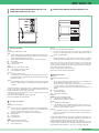
Videovox Pro GB Series Guida utente
- Categoria
- Videoregistratori digitali (DVR)
- Tipo
- Guida utente
La pagina si sta caricando...

GROUP S.P.A.
MT VCC 01
Avvertenze:
• Effettuare l’installazione seguendo scrupolosamente le istruzioni fornite dal costruttore ed in conformità alle norme vigenti.
• Tutti gli apparecchi devono essere destinati esclusivamente all’uso per cui sono stati concepiti. Comelit Group S.p.A. declina ogni
responsabilità per un utilizzo improprio degli apparecchi, per modifiche effettuate da altri a qualunque titolo e scopo, per l’uso di
accessori e materiali non originali.
• Tutti i prodotti sono conformi alle prescrizioni delle direttive 2006/95/CE (che sostituisce la direttiva 73/23/CEE e successivi
emendamenti) e ciò è attestato dalla presenza della marcatura CE sugli stessi.
• Evitare di porre i fili di montante in prossimità di cavi di alimentazione (230/400V).
Instructions:
• Install the equipment by carefully following the instructions given by the manufacturer and in compliance with the legislation in force.
• All the equipment must only be used for the purpose it was built for. Comelit Group S.p.A. declines any responsibility for improper
use of the apparatus, for modifications made by others under any title or scope, and for the use of accessories and materials which
are not the original ones.
• All the products comply with the requirements of the 2006/95/CE directives (which replace the 73/23/CEE directives and the
successive amendments). This is proved by the CE mark on the products.
• Do not run the riser wires in proximity of the power supply cables (230/400V).
Instructions
• Effectuer l’installation en suivant scrupuleusement les instructions fournies par le constructeur et conformément aux normes en
vigueur.
• Tous les appareils doivent être strictement destinés à l’emploi pour lequel ils ont été conçus. Comelit Group S.p.A. décline toute
responsabilité en cas de mauvais usage des appareils, pour des modifications effectuées par d’autres personnes pour n’importe
quelle raison et pour l’ utilisation d’accessoires non fournis par nous.
• Tous les produits sont conformes aux exigences des directives 2006/95/CE (qui remplacent les directives 73/23/CEE et
amendements successifs). Cette conformité est signalée par le symbole CE figurant sur les produits.
• Eviter de placer les fils de montant à proximité des câbles d’alimentation (230/400 V).
I
GB
F

MT VCC 01
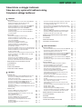
SOMMARIO
•
POSTI ESTERNI
- Istruzioni per installazione posto esterno audio-video Powercom pag. 2
- Istruzioni per montaggio modulo informativo Art. 3326 pag. 4
- Realizzazione cartellini portanome Powercom pag. 4
- Istruzioni per installazione posto esterno audio-video Vandalcom pag. 5
- Istruzioni per installazione posto esterno audio-video Roma pag. 7
- Istruzioni per installazione posto esterno audio N-AV/4 pag. 8
- Istruzioni di montaggio posto esterno audio-video Powerpost
con apertura verticale pag. 9
- Istruzioni di montaggio posto esterno audio-video Powerpost
con apertura laterale pag. 10
•
POSTI INTERNI
- Descrizione monitor Bravo e informazioni utente pag. 11
- Istruzioni per installazione posto interno Bravo pag. 12
- Istruzioni per installazione scheda opzionale Art. 5733 o Art. 5734
(solo per monitor BRAVO) pag. 14
- Inserimento mascherine per monitor Bravo pag. 15
- Descrizione monitor Genius e informazioni utente pag. 16
- Istruzioni per installazione posto interno Genius pag. 17
- Caratteristiche tecniche staffa di fissaggio Art. 5705
per monitor Bravo e Genius pag. 19
- Descrizione monitor Diva e citofono viva-voce e informazioni utente pag. 20
- Istruzioni per installazione posto interno Diva audio-video Art. 4780 pag. 22
- Istruzioni per installazione posto interno Diva audio
Art. 4781 su staffa Art. 4786 pag. 24
- Caratteristiche tecniche staffa di fissaggio Art . 4786 per monitor Diva pag. 26
- Istruzioni per installazione citofono Style Art. 2602 e Art. 2602E pag. 27
- Citofono Style Art. 2602 pag. 28
- Citofono Style Art. 2602E pag. 29
- Descrizione citofono da parete Okay e morsettiera pag. 30
- Istruzioni per installazione citofono da parete Okay Art. 2402W pag. 30
- Descrizione centrale di alimentazione audio-video Art. 4594 pag. 31
•
NORME GENERALI PER INSTALLAZIONE, COLLAUDO
E FUNZIONAMENTO pag. 32
•
RICERCA GUASTI pag. 32
•
SCHEMI DI COLLEGAMENTO pag. 34
•
VARIANTI AGLI SCHEMI DI IMPIANTO pag. 34
CONTENTS
•
EXTERNAL UNITS
- Instructions for installing an external Powercom audio-video unit page 2
- Instructions for assembling an informative module Art. 3326 page 4
- Creating Powercom name tags page 4
- Instructions for installing an external Vandalcom audio-video unit page 5
- Instructions for installing an external Roma audio-video unit page 7
- Instructions for installing an external N-AV/4 audio unit page 8
- Instructions for assembling an external Powerpost audio-video unit
with vertical opening page 9
- Instructions for assembling an external Powerpost audio-video unit
with side opening page 10
•
INTERNAL UNITS
- Description of Bravo monitor and user information page 11
- Instructions for installing an internal Bravo unit page 12
- Instructions for installing an optional card Art. 5733 or Art. 5734
(only for a BRAVO monitor) page 14
- Inserting masks for a Bravo monitor page 15
- Description of Genius monitor and user information page 16
- Instructions for installing an internal Genius unit page 17
- Technical features of mounting bracket Art. 5705 for Bravo
and Genius monitor page 19
- Description of Diva monitor and hands free intercom
and user information page 20
- Instructions for installing an internal Diva audio-video unit Art. 4780 page 22
- Instructions for installing an internal Diva audio unit Art. 4781
on a mounting bracket Art. 4786 page 24
- Technical features of mounting bracket Art. 4786 for Diva monitor page 26
- Instructions for installing a Style intercom Art. 2602 and Art. 2602E page 27
- Style intercom art. 2602 pag. 28
- Style intercom art. 2602E pag. 29
- Description of Okay wall-mounted intercom and terminal board page 30
- Instructions for installing a wall-mounted intercom Art. 2402W page 30
- Description of audio-video power unit Art. 4594 page 31
•
GENERAL INSTRUCTIONS FOR INSTALLATION, TESTING
AND OPERATION page 35
•
FAULT FINDING page 35
•
CONNECTION DIAGRAMS page 37
•
VARIATIONS TO SYSTEM DIAGRAMS page 37
TABLE DES MATIÈRES
•
POSTES EXTÉRIEURS
- Instructions d'installation du poste extérieur audio-vidéo Powercom page 2
- Instructions de montage du module d'informations Art. 3326 page 4
- Réalisation d'étiquettes porte-noms Powercom page 4
- Instructions d'installation du poste extérieur audio-vidéo Vandalcom page 5
- Instructions d'installation du poste extérieur audio-vidéo Roma page 7
- Instructions d'installation du poste extérieur audio N-AV/4 page 8
- Instructions de montage du poste extérieur audio-vidéo Powerpost
à ouverture verticale page 9
- Instructions de montage du poste extérieur audio-vidéo Powerpost
à ouverture latérale page 10
•
POSTES INTÉRIEURS
- Description du moniteur Bravo et informations utilisateur page 11
- Instructions d'installation du poste intérieur Bravo page 12
- Instructions d'installation de la carte en option
Art. 5733 ou Art. 5734 (uniquement pour le moniteur BRAVO) page 14
- Insertion des caches pour le moniteur Bravo page 15
- Description du moniteur Genius et informations utilisateur page 16
- Instructions d'installation du poste intérieur Genius page 17
- Caractéristiques techniques du support de montage Art. 5705
pour moniteurs Bravo et Genius page 19
- Description du moniteur Diva et de l'interphone mains-libres
et informations utilisateur page 20
- Instructions d'installation du poste intérieur Diva audio-vidéo
Art. 4780 page 22
- Instructions d'installation du poste intérieur Diva audio Art.
4781 sur support de montage Art. 4786 page 24
- Caractéristiques techniques du support de montage Art. 4786
pour moniteur Diva page 26
- Instructions d'installation de l'interphone Style Art. 2602 et 2602E page 27
- Interphone Style art. 2602 pag. 28
- Interphone Style art. 2602E pag. 29
- Description de l'interphone mural Okay et du bornier page 30
- Instructions d'installation de l'interphone mural Okay Art. 2402W page 30
- Description de la centrale d'alimentation audio-vidéo Art. 4594 page 31
•
NORMES GÉNÉRALES D'INSTALLATION, DE TEST
ET DE FONCTIONNEMENT page 38
•
DÉPANNAGE page 38
•
SCHÉMAS DE CONNEXION page 40
•
VARIANTES DES SCHÉMAS D'INSTALLATION page 40
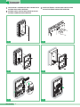
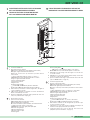
Videocitofonia a cablaggio tradizionale
Video door entry system with traditional cabling
Visiophonie à câblage traditionnel
MT VCC 01
1
F
I
GB
La pagina si sta caricando...

MT VCC 01
3
MT VCC 01
1
2
3
360˚
+
-
+
-
MIC
5
4
2
3
1
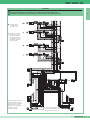
Posizione alternativa del microfono
Alternative microphone position
Autre position du microphone
Carla
Rossi
open
close
7 8
9 10
11 12
I
GB
F

GROUP S.P.A.
MT VCC 01
4
10
2
1
10
15
1
2
3 4
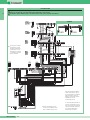
Rossi
Aldo
Aldo
Rossi
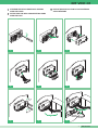
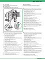
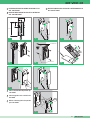
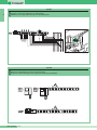
Utilizzare una striscia adesiva trasparente per etichettatrice (tipo Dymo) come mostrato in figura.
Use a transparent adhesive strip for a label maker (of the Dymo type) as shown in the figure.
Utilisez une bande adhésive transparente pour étiqueteuse (de type Dymo), comme illustré dans la figure.
PER UNA OTTIMALE REALIZZAZIONE DEI CARTELLINI PORTANOME SI CONSIGLIA DI PROCEDERE NEL SEGUENTE MODO:
NAME TAGS CAN BE BEST PRODUCED AS FOLLOWS:
POUR UNE REALISATION OPTIMALE DES ETIQUETTES PORTE-NOMS, IL EST CONSEILLE DE PROCEDER COMME SUIT:
I
GB
F
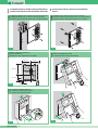
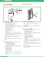
ISTRUZIONI PER MONTAGGIO MODULO INFORMATIVO
ART. 3326
INSTRUCTIONS FOR ASSEMBLING AN INFORMATIVE
MODULE ART. 3326
INSTRUCTIONS DE MONTAGE DU MODULE
D'INFORMATIONS ART. 3326
FI
GB
La pagina si sta caricando...
La pagina si sta caricando...
La pagina si sta caricando...
La pagina si sta caricando...
La pagina si sta caricando...
La pagina si sta caricando...

MT VCC 01
11
MT VCC 01
8
4
5
6
7
9
1
2
3
4
5
6
12
3
2
1
13
1
2
11
10
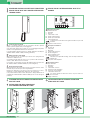
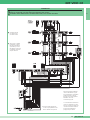
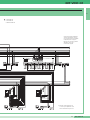
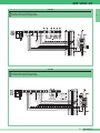
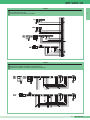
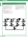
I Monitor Videocitofonici Comelit della serie Bravo Art. 5701 (Monitor in bianco e
nero) e Art. 5702 (Monitor a colori), sono compatibili con i Monitor delle serie:
Eurocom, Videocom, Genius e Diva. La staffa di fissaggio Art. 5705 completa il
Monitor e determina il sistema di cablaggio Tradizionale.
1. Selettore suoneria/servizio Privacy a 3 posizioni:
Posizione sinistra: Suoneria volume massimo.
Posizione centrale: Suoneria volume medio.
Posizione destra : Attivazione funzione Privacy.
(per servizio Privacy si intende l’esclusione della chiamata dal posto esterno o
intercomunicante; l’attivazione della funzione Privacy è evidenziata dalla
comparsa di un indicatore rosso a lato del selettore).
2. Led di segnalazione (disponibile di serie).
3. Pulsante Apriporta .
4. Pulsante disponibile di serie, riferimento in morsettiera
(solitamente utilizzato per funzione Autoaccensione).
5. Pulsante disponibile di serie (riferimento in morsettiera P2C2).
6. Pulsanti opzionali per attivazione funzioni supplementari
(A)
.
7. Pulsanti o Led opzionali per attivazione/visualizzazione funzioni supplementari
(B)
.
8. Schermo per visualizzazione immagine da posto esterno.
9. Cartoncino intercambiabile e personalizzabile tramite Kit opzionale.
10. Manopola regolazione luminosità (ruotare in senso orario per aumentare la
luminosità).
11. Manopola regolazione contrasto per monitor in bianco e nero o regolazione
intensità colore per monitor a colori (ruotare in senso orario per aumentare il
valore).
12. Etichetta memo-pulsanti su cui è possibile riportare la funzione dei pulsanti del
Monitor (da applicare sul Monitor sotto la cornetta come indicato in figura).
L’etichetta adesiva è allegata ai Monitor Art. 5701 e Art. 5702 nel manuale utente
FT BRAVO 01.
13. Cornetta Monitor (sollevare la cornetta per iniziare la comunicazione).
(A)
Pulsante disponibile con scheda opzionale Art. 5733.
(B)
Pulsante disponibile con scheda opzionale Art. 5733.
Led di visualizzazione disponibile con scheda opzionale Art. 5734.
Comelit intercom monitors of the Bravo series Art. 5701 (black and white
monitors) and Art. 5702 (colour monitors) are compatible with monitors of the
series: Eurocom, Videocom, Diva. The mounting bracket Art. 5705 completes the
monitor and determines the traditional wiring system.
1. Ringtone/Privacy service selector with 3 positions:
Left position: Maximum ringtone volume.
Central position: Medium ringtone volume.
Right position : Activation of Privacy function.
(privacy service means the exclusion of the call from the external or
intercommunicating unit; activation of the Privacy function is indicated by the
appearance of a red indicator next to the selector).
2. Signalling LED (available as standard).
3. Door opening button .
4. Button available as standard; reference in terminal board
(normally used for the Autostart function).
5. Button available as standard (reference in terminal board P2C2).
6. Optional buttons for activating additional functions
(A)
.
7. Optional buttons or LEDs for activating/displaying additional functions
(B)
.
8. Screen for displaying the image from the external unit.
9. Interchangeable card, customisable using the optional kit.
10. Brightness adjustment knob (turn clockwise to increase brightness).
11. Knob for adjusting the contrast on black and white monitors or for adjusting
colour intensity on colour monitors (turn clockwise to increase the value).
12. Button reminder label for specifying the functions of the monitor buttons (to be
applied on the monitor under the receiver as shown in the figure). The adhesive
label is enclosed with the monitors Art. 5701 and Art. 5702 in the FT BRAVO 01
user guide.
13. Monitor receiver (pick up the receiver to start communication).
(A)
Button available with optional card Art. 5733.
(B)
Button available with optional card Art. 5733.
Display LED available with optional card Art. 5734.
Les moniteurs des visiophones Comelit de la série Bravo Art. 5701 (moniteur noir
et blanc) et Art. 5702 (moniteur couleur) sont compatibles avec les moniteurs de
la série : Eurocom, Videocom, Diva. Le support de montage Art. 5705 complète
le moniteur et détermine le système de câblage traditionnel.
1. Sélecteur de sonnerie/fonction Privé à 3 positions :
Position de gauche : volume maximal.
Position centrale : volume moyen.
Position de droite : activation de la fonction Privé.
(la fonction Privé signifie que l'appel ne sonne pas sur le poste extérieur ou sur le
standard ; l’activation de la fonction Privé est indiquée par un voyant rouge qui
s'allume à côté du sélecteur).
2. Voyant de signalisation (disponible en série).
3. Bouton d'ouverture de porte .
4. Bouton disponible en série, référencé dans le bornier
(habituellement utilisé pour la fonction d'auto-allumage).
5. Bouton disponible en série (référencé dans le bornier P2C2).
6. Bou tons en option pour l'activation de fonctions supplémentaires
(A)
.
7. Boutons ou voyants en option pour l'activation/l'affichage de fonctions
supplémentaires
(B)
.
8. Écran de visualisation des images sur le poste extérieur.
9. Carte interchangeable et personnalisable à l'aide d'un kit en option.
10. Bouton de réglage de la luminosité (faire tourner dans le sens des aiguilles d'une
montre pour augmenter la luminosité).
11. Bouton de réglage du contraste pour les moniteurs noir et blanc ou de réglage de
l'intensité des couleurs pour les moniteurs couleur (faire tourner dans le sens des
aiguilles d'une montre pour augmenter la valeur).
12. Étiquette des boutons de mémoire sur laquelle il est possible d'indiquer la
fonction des boutons du moniteur (à insérer sur le moniteur, sous le combiné,
comme indiqué dans la figure). L'étiquette adhésive est livrée avec les moniteurs
Art. 5701 et Art. 5702 dans le manuel utilisateur FT BRAVO 01.
13. Combiné du moniteur (soulever le combiné pour démarrer la communication).
(A)
Bouton disponible avec la carte en option Art. 5733.
(B)
Bouton disponible avec la carte en option Art. 5733.
Voyant d'affichage disponible avec la carte en option Art. 5734.
POSTI INTERNI
Descrizione monitor Bravo e informazioni utente
INTERNAL UNITS
Description of Bravo monitor and user information
POSTES INTÉRIEURS
Description du moniteur Bravo et informations utilisateur
FI
GB
GB
F
I

GROUP S.P.A.
MT VCC 01
12
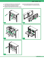
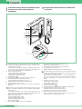
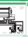
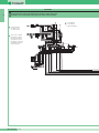
145 cm
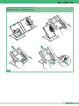
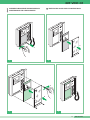
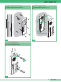
Installazione Staffa Art. 5705 su scatola serie civile 503 (Art. 4517).
Installing bracket Art. 5705 on civil series 503 box (Art. 4517).
Installation du support de montage Art. 5705 sur boîtier série civile 503 (Art. 4517).
1
2
3
4
5
6
10,2 cm 11 cm
14,4 cm
8,1 cm
1,4 cm
1,4 cm
1
2
3
4
5
6
3
2
1
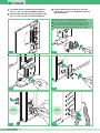
Procedura per togliere il Monitor.
Procedure for removing the monitor.
Procédure de retrait du moniteur.
1
3
5
I
GB
F
Misure di ingombro del Monitor.
Monitor dimensions.
Dimensions d'encombrement du moniteur.
I
GB
F
I
GB
F
Installazione a muro Staffa Art. 5705 con 4 viti a tassello.
Wall-mounted installation of bracket Art. 5705 by means of 4 screws with rawlplugs.
Installation murale du support Art. 5705 avec 4 vis à cheville.
2
1
2
3
4
5
6
C
V
2
C
V
7
C
V
1
C
V
6
C
V
5
C
V
3
C
V
4
1
2
3
4
5
6
1
2
Procedura di aggancio Monitor.
Monitor attachment procedure.
Procédure de mise en place du moniteur.
4
I
GB
F
I
GB
F
ISTRUZIONI PER INSTALLAZIONE POSTO INTERNO BRAVO
INSTRUCTIONS FOR INSTALLING AN INTERNAL BRAVO UNIT
INSTRUCTIONS D'INSTALLATION DU POSTE INTÉRIEUR
BRAVO
FI
GB

MT VCC 01
13
MT VCC 01
1
2
3
4
5
6
2
3
1
2
3
4
5
6
1
6
5
4
3
2
1
6
5
4
6
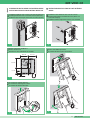
Montaggio del monitor sulla base da tavolo Art. 5712.
Mounting the monitor on the table base Art. 5712.
Montage du moniteur sur support de table Art. 5712.
I
GB
F
La pagina si sta caricando...
La pagina si sta caricando...

GROUP S.P.A.
MT VCC 01
16
+
--
1
7
6
3
2
5
4
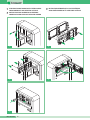
Il monitor Genius Art. 5801 (monitor in bianco e nero) e Art. 5802 (monitor a
colori) può essere utilizzato in alternativa al monitor Bravo sulla staffa Art. 5705 e
con la base da tavolo Art. 5712.
Per l'installazione e il cablaggio fare riferimento ai suddetti prodotti. Gli accessori
Art. 5733 e Art. 5734, per la gestione dei pulsanti e dei LED aggiuntivi, non
possono essere utilizzati in abbinamento al monitor Genius.
1. Selettore suoneria a 3 posizioni:
Posizione sinistra: Suoneria volume massimo.
Posizione centrale: Suoneria volume medio.
Posizione destra: Suoneria volume minimo.
2. Pulsante Apriporta .
3. Cornetta monitor (sollevare la cornetta per iniziare la comunicazione).
4. Pulsante disponibile di serie, riferimento in morsettiera
(solitamente utilizzato per funzione Autoaccensione).
5. Pulsante disponibile di serie (riferimento in morsettiera P2C2).
6. Schermo 4” bianco e nero o 3,5” colori.
7. Manopola regolazione luminosità (ruotare in senso antiorario per aumentare la
luminosità).
The Genius monitor Art. 5801 (black and white) and Art. 5802 (colour) can be
used as an alternative to the Bravo monitor on the bracket Art. 5705 and with the
table base Art. 5712.
For installation and wiring, refer to the above-mentioned products. The
accessories Art. 5733 and Art. 5734 for management of additional buttons and
LEDs cannot be used in conjunction with the Genius monitor.
1. Ringtone selector with 3 positions:
Left position: Maximum ringtone volume.
Central position: Medium ringtone volume.
Right position: Minimum ringtone volume.
2. Door opening button .
3. Monitor receiver (pick up the receiver to start communication).
4. Button available as standard; reference in terminal board
(normally used for the Autostart function).
5. Button available as standard (reference in terminal board P2C2).
6. 4” black and white or 3.5” colour screen.
7. Brightness adjustment knob (turn anti-clockwise to increase brightness).
Le moniteur Genius Art. 5801 (moniteur noir et blanc) et Art. 5802 (moniteur
couleur) peut être utilisé à la place du moniteur Bravo sur le support de montage
Art. 5705 et sur le support de table Art. 5712.
Pour l'installation et le câblage, reportez-vous aux produits mentionnés ci-
dessus. Les accessoires Art. 5733 et Art. 5734 pour la gestion des boutons et
des voyants supplémentaires, ne peuvent pas être utilisés avec le moniteur
Genius.
1. Sélecteur de sonnerie à 3 positions:
Position de gauche: volume maximal.
Position centrale : volume moyen.
Position de droite: volume minimal.
2. Bouton d'ouverture de porte .
3. Combiné du moniteur (soulever le combiné pour démarrer la communication).
4. Bouton disponible en série, référencé dans le bornier
(habituellement utilisé pour la fonction d'auto-allumage).
5. Bouton disponible en série (référencé dans le bornier P2C2).
6. Écran 4 pouces noir et blanc ou 3,5 pouces en couleur.
7. Bouton de réglage de la luminosité (faire tourner dans le sens inverse des
aiguilles d'une montre pour augmenter la luminosité).
I
GB
F
DESCRIZIONE MONITOR GENIUS E INFORMAZIONI UTENTE
DESCRIPTION OF GENIUS MONITOR AND USER
INFORMATION
DESCRIPTION DU MONITEUR GENIUS ET INFORMATIONS
UTILISATEUR
FI
GB

MT VCC 01
17
MT VCC 01
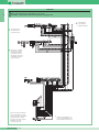
145 cm
Installazione Staffa Art. 5705 su scatola serie civile 503 (Art. 4517).
Installing bracket Art. 5705 on civil series 503 box (Art. 4517).
Installation du support de montage Art. 5705 sur boîtier série civile 503 (Art. 4517).
10,3 cm 10,1 cm
14,4 cm
8,1 cm
1,4 cm
1,4 cm
3
2
1
Procedura per togliere il Monitor.
Procedure for removing the monitor.
Procédure de retrait du moniteur.
1
3
5
I
GB
F
Misure di ingombro del Monitor.
Monitor dimensions.
Dimensions d'encombrement du moniteur.
I
GB
F
I
GB
F
Installazione a muro Staffa Art. 5705 con 4 viti a tassello.
Wall-mounted installation of bracket Art. 5705 by means of 4
screws with rawlplugs.
Installation murale du support Art. 5705 avec 4 vis à cheville.
2
1234
ON
5678
DIP
1234
ON
5678
DIP
1
2
Procedura di aggancio Monitor.
Monitor attachment procedure.
Procédure de mise en place du moniteur.
4
I
GB
I
GB
F
ISTRUZIONI PER INSTALLAZIONE POSTO INTERNO GENIUS
INSTRUCTIONS FOR INSTALLING AN INTERNAL GENIUS UNIT
INSTRUCTIONS D'INSTALLATION DU POSTE INTÉRIEUR
GENIUS
FI
GB
F

GROUP S.P.A.
MT VCC 01
18
2
3
6
5
4
1
6
Montaggio del monitor sulla base da tavolo Art. 5712.
Mounting the monitor on the table base Art. 5712.
Montage du moniteur sur support de table Art. 5712.
I
GB
F

MT VCC 01
19
MT VCC 01
4
2
3
1
5
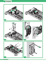
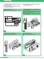
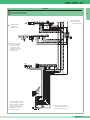
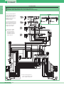
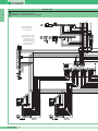
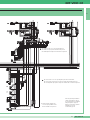
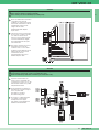
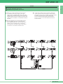
1. Connettore Staffa-Monitor.
2. Morsetti di connessione impianto:
LED 1 Ingresso alimentazione Led di segnalazione (max 12V DC).
SD Ingresso segnale di chiamata intercomunicante.
AI Morsetto di connessione per attivazione opzionale funzione
autoaccensione.
+ - Ingresso di alimentazione Monitor positivo (+) e massa (-).
V SH / SH V Ingresso/uscita parallela segnale video e schermo.
S Ingresso segnale di chiamata elettronica.
2 Ingresso altoparlante Monitor.
3 Uscita microfono Monitor.
4 Negativo fonica.
P1 Pulsante Apriporta .
Contatti C.NO. (24V-100mA max) Pulsante 1 del Monitor.
P2 C2 Contatti C.NO. (24V-100mA max) Pulsante 2 del Monitor.
3. CV1 Ponticello per la chiusura 75 ohm del segnale video, da tagliare in
caso di collegamento in cascata.
4. CV3 Ponticello da tagliare per impedire l’accensione automatica del
Monitor su chiamata da posto esterno.
5. Spazio per alloggiamento morsettiera scheda opzionale Art. 5733 o Art.
5734 ( solo per monitor Bravo vedi pag. 14).
1. Bracket-monitor connector.
2. System connection terminals:
LED 1 Signalling LED power input (max. 12 V DC).
SD Intercommunicating call signal input.
AI Connection terminal for optional activation of the Autostart function.
+ - Monitor power input, positive (+) and earth (-).
V SH/SH V Video and screen signal parallel input/output.
S Electronic call signal input.
2 Monitor loudspeaker input.
3 Monitor microphone output.
4 Sound negative.
P1 Door opening button .
C.NO contacts. (24 V-100 mA max.) Button 1 of the monitor.
P2 C2 C.NO contacts. (24 V-100 mA max.) Button 2 of the monitor.
3. CV1 Bridge for 75-ohm closing of the video signal, to be cut in the case
of cascade connection.
4. CV3 Bridge to be cut in order to prevent automatic start-up of the monitor
in response to a call from the external unit.
5. Space for terminal board housing for optional card Art. 5733 or Art. 5734
(only for a BRAVO monitor, see page 14).
1. Connecteur support-moniteur.
2. Bornes de connexion du système:
LED 1 Entrée d'alimentation voyant de signalisation (max. 12V DC).
SD Entrée du signal d'appel intercommunicant.
AI Borne de connexion pour l'activation optionnelle de la fonction d'auto-
allumage.
+ - Entrée d'alimentation positive (+) et de masse (-) du moniteur.
V SH / SH V Entrée/sortie parallèle du signal vidéo et écran.
S Entrée du signal d'appel électronique.
2 Entrée haut-parleur du moniteur.
3 Sortie microphone du moniteur.
4 Négatif phonie.
P1 Bouton d'ouverture de porte .
Contacts C.NO. (24V-100mA max) Bouton 1 du moniteur.
P2 C2 Contacts C.NO. (24V-100mA max) Bouton 2 du moniteur.
3. CV1 Cavalier de fermeture 75 ohm du signal vidéo, qui doit être coupé
en cas de connexion en cascade.
4. CV3 Cavalier à couper pour empêcher l'allumage automatique du
moniteur lors d'un appel provenant d'un poste extérieur.
5. Logement du bornier de la carte en option Art. 5733 ou Art. 5734
(uniquement pour le moniteur Bravo, voir page 14).
I
GB
F
CARATTERISTICHE TECNICHE STAFFA DI FISSAGGIO
ART. 5705 PER MONITOR BRAVO E GENIUS
TECHNICAL FEATURES OF MOUNTING BRACKET
ART. 5705 FOR BRAVO AND GENIUS MONITOR
CARACTERISTIQUES TECHNIQUES DU SUPPORT DE
MONTAGE ART. 5705 POUR MONITEURS BRAVO ET GENIUS
FI
GB

GROUP S.P.A.
MT VCC 01
20
9
9
1
2
3
4
5
6
7
8
+
-
+
-
6
8
5
4
3
7
2
Il videocitofono viva-voce serie Diva Art. 4780 e il citofono viva-voce Art. 4781
sono compatibili con i monitor delle serie: Bravo, Genius, Eurocom e
Videocom. La staffa di fissaggio Art. 4786 completa il posto interno e determi-
na il sistema di cablaggio Tradizionale.
1. Regolazione luminosità (ruotare in senso orario per aumentare la luminosità)
(solo Art. 4780).
2. Regolazione volume di chiamata (ruotare in senso orario per aumentare il
volume).
3. Pulsante Apriporta .
4. Pulsante per attivare e disattivare la fonica dopo una chiamata .
Dopo l’attivazione (led blu acceso) la conversazione è in modalità Parla/
Ascolta automatica*.
5. Pulsanti (C.NO.) liberi (1) (2) (3) di serie.
6. Pulsante a più funzioni:
6A ATTIVAZIONE E DISATTIVAZIONE SERVIZIO PRIVACY: esclusione
chiamata dal posto esterno o dal centralino di portineria.
6B Modalità PARLA/ASCOLTA manuale: con monitor in fonica premere il
pulsante per parlare e rilasciarlo per ascoltare*.
Attenzione: Una volta attivata la modalità Parla/Ascolta manuale, questa si
mantiene fino alla chiamata successiva.
6C CONTATTO LIBERO (C.NO.).
Attenzione: In questo caso non è più disponibile la modalità
PARLA/ASCOLTA manuale.
7. Led blu di segnalazione fonica (l’accensione indica che la fonica è attivata).
8. Led rosso di segnalazione servizio privacy attivo, oppure durante una
comunicazione segnala lo stato della conversazione*:
- spento: a questo Monitor si sente la fonica proveniente dal posto esterno o
da un altro apparecchio intercomunicante;
- acceso: la fonica proveniente da questo Monitor si sente presso il posto
esterno o presso un altro apparecchio intercomunicante.
9. Ganci di fissaggio.
* Attenzione: se il led rosso lampeggia è necessario rimanere
in ascolto e aspettare che si spenga prima di parlare.
DESCRIZIONE MONITOR E CITOFONO VIVA-VOCE DIVA
E INFORMAZIONI UTENTE
DESCRIPTION OF DIVA MONITOR AND HANDS FREE
INTERCOM AND USER INFORMATION
DESCRIPTION DU MONITEUR ET DE L'INTERPHONE
MAINS-LIBRES DIVA ET INFORMATIONS UTILISATEUR
FI
GB
I
La pagina si sta caricando...

GROUP S.P.A.
MT VCC 01
22
11,5 mm
17,5 mm
74,5 mm
260 mm
127,5 mm
11,5 mm
17,5 mm
95 mm
==
503
C
1
Misure di ingombro del Monitor.
Monitor dimensions.
Dimensions d'encombrement du moniteur.
I
GB
F
145 cm
3
Installazione monitor Art. 4780 a parete.
Installing a wall-mounted monitor Art. 4780.
Installation murale du moniteur Art. 4780.
I
GB
F
2
1
4
Procedura di aggancio Monitor.
Monitor attachment procedure.
Procédure de mise en place du moniteur.
I
GB
F
145 cm
63 mm
2
Installazione monitor Art. 4780 su scatola da incasso. La
scatola serie civile 503 (Art. 4517) deve essere murata in
posizione orizzontale.
Installing a wall-mounted monitor Art. 4780 on a housing
box. The civil series 503 box (Art. 4517) must be embedded
in the wall in a horizontal position.
Installation du moniteur Art. 4780 sur boîtier à encastrer.
Le boîtier série civile 503 (Art. 4517) doit être monté au mur
en position horizontale.
I
GB
F
ISTRUZIONI PER INSTALLAZIONE POSTO INTERNO DIVA
AUDIO-VIDEO ART. 4780
INSTRUCTIONS FOR INSTALLING AN INTERNAL DIVA
AUDIO-VIDEO UNIT ART. 4780
INSTRUCTIONS D'INSTALLATION DU POSTE INTÉRIEUR
AUDIO-VIDÉO DIVA ART. 4780
FI
GB

MT VCC 01
23
MT VCC 01
1
3
2
5
Procedura per togliere il Monitor.
Procedure for removing the monitor.
Procédure de retrait du moniteur.
I
GB
F
5
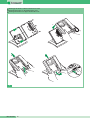
Montaggio del Monitor sulla base da tavolo Art. 4782.
Mounting the monitor on the table base Art. 4782.
Montage du moniteur sur support de table Art. 4782.
I
GB
F
1
1
2
2

GROUP S.P.A.
MT VCC 01
24
1
Misure di ingombro del Monitor.
Monitor dimensions.
Dimensions d'encombrement du moniteur.
I
GB
F
145 cm
63 mm
2
Installazione monitor Art. 4781 su scatola da incasso. La scatola serie civile 503 (Art. 4517) deve essere murata in posizione verticale.
Installing a wall-mounted monitor Art. 4781 on a housing box. The civil series 503 box (Art. 4517) must be embedded in the wall in a vertical position.
Installation du moniteur Art. 4781 sur boîtier à encastrer. Le boîtier série civile 503 (Art. 4517) doit être monté au mur en position verticale.
I
GB
F
ISTRUZIONI PER INSTALLAZIONE POSTO INTERNO DIVA
AUDIO ART. 4781 SU STAFFA ART. 4786
INSTRUCTIONS FOR INSTALLING AN INTERNAL DIVA AUDIO
UNIT ART. 4781 ON A MOUNTING BRACKET ART. 4786
INSTRUCTIONS D'INSTALLATION DU POSTE INTÉRIEUR
AUDIO DIVA ART. 4781 SUR SUPPORT DE MONTAGE
ART. 4786
FI
GB
11,5 mm
17,5 mm
74,5 mm
260 mm
11,5 mm
17,5 mm
95 mm
==
503
C

MT VCC 01
25
MT VCC 01
145 cm
3
Installazione monitor Art. 4781 a parete.
Installing a wall-mounted monitor Art. 4781.
Installation murale du moniteur Art. 4781.
I
GB
F
3
4
2
1
1
2
3
5
Procedura per togliere Monitor.
Procedure for removing the monitor.
Procédure de retrait du moniteur.
I
GB
F
3
4
2
1
2
1
4
Procedura di aggancio Monitor.
Monitor attachment procedure.
Procédure de mise en place du moniteur.
I
GB
F

GROUP S.P.A.
MT VCC 01
26
1. Connettore Staffa-Monitor.
2. Morsetti di connessione impianto:
C4 P4 Contatti C.NO. (24V-100mA max) Pulsante 4 del Monitor.
C3 P3 Contatti C.NO. (24V-100mA max) Pulsante 3 del Monitor.
C2 P2 Contatti C.NO. (24V-100mA max) Pulsante 2 del Monitor.
Contatti C.NO. (24V-100mA max) Pulsante 1 del Monitor
(normalmente utilizzato per funzione autoaccensione).
P1 Pulsante Apriporta .
4 Negativo fonica.
3 Uscita microfono Monitor.
2 Ingresso altoparlante Monitor.
AF Ingresso commutazione per impianti intercomunicanti.
+ LED
Ingresso segnalazione Led (+12VDC). Il led blu lampeggia se il segnale è presente.
SD Ingresso segnale di chiamata intercomunicante.
S Ingresso segnale di chiamata elettronica.
AI Morsetto di connessione per attivazione opzionale funzione autoaccensione.
+V Ingresso alimentazione Staffa.
V/V1 Ingresso segnale video coassiale.
SH/V2 Schermo segnale video coassiale.
+ - Ingresso di alimentazione Monitor positivo (+) e massa (-).
SEN Ingresso di reset per porta audio.
3. J5 Doppio Jumper:
Impostare J5 in posizione TR.
4. J3 Jumper da spostare per liberare il Pulsante 4 del Monitor.
5. CV1 Ponticello per la chiusura 75 ohm del segnale video, da tagliare in caso di
collegamento in cascata.
6. CV3 Ponticello da tagliare per impedire l’accensione automatica del Monitor su
chiamata da posto esterno.
7. J2 Ponticello da tagliare per disattivazione funzione segreto di conversazione.
8. TM1 Volume Altoparlante DIVA.
9. TM2 Volume Microfono DIVA verso posto esterno.
10. TM3 Sensibilità del Microfono per la commutazione dei canali di fonica (regolata
in posizione ideale dal produttore).
11. TM5 Ampiezza segnale Video (regolata in posizione ideale dal produttore).
1. Bracket-monitor connector.
2. System connection terminals:
C4 P4 C.NO contacts. (24 V-100 mA max.) Button 4 of the monitor.
C3 P3 C.NO contacts. (24 V-100 mA max.) Button 3 of the monitor.
C2 P2 C.NO contacts. (24 V-100 mA max.) Button 2 of the monitor.
C.NO contacts. (24 V-100 mA max.) Button 1 of the monitor
(normally used for the Autostart function).
P1 Door opening button .
4 Sound negative.
3 Monitor microphone output.
2 Monitor loudspeaker input.
AF Switching input for intercommunicating systems.
+ LED
Input for LED signalling (+12 V DC). The blue LED flashes if the signal is present.
SD Intercommunicating call signal input.
S Electronic call signal input.
AI Connection terminal for optional activation of the Autostart function.
+V Bracket power input.
V/V1 Coaxial video signal input.
SH/V2 Coaxial video signal screen.
+ - Monitor power input, positive (+) and earth (-).
SEN Audio port reset input.
3. J5 Double jumper:
Set J5 to the TR position.
4. J3 Jumper to be moved to free Button 4 of the monitor.
5. CV1 Bridge for 75-ohm closing of the video signal, to be cut in the case of
cascade connection.
6. CV3 Bridge to be cut in order to prevent automatic start-up of the monitor in
response to a call from the external unit.
7. J2 Bridge to be cut to deactivate the conversation secret function.
8. TM1 DIVA loudspeaker volume.
9. TM2 DIVA microphone volume to external unit.
10. TM3 Microphone sensitivity for switching audio channels (set to the best
position by the manufacturer).
11. TM5 Video signal amplitude (set to the best position by the manufacturer).
1. Connecteur support-moniteur.
2. Bornes de connexion du système:
C4 P4 Contacts C.NO. (24V-100mA max) Bouton 4 du moniteur.
C3 P3 Contacts C.NO. (24V-100mA max) Bouton 3 du moniteur.
C2 P2 Contacts C.NO. (24V-100mA max) Bouton 2 du moniteur.
Contacts C.NO. (24V-100mA max) Bouton 1 du moniteur
(habituellement utilisé pour la fonction d'auto-allumage).
P1 Bouton d'ouverture de porte .
4 Négatif phonie.
3 Sortie microphone du moniteur.
2 Entrée haut-parleur du moniteur.
AF Entrée de commutation pour appareils intercommunicants.
+ LED Entrée du signal lumineux (+12VDC). Le voyant bleu clignote si un
signal est présent.
SD Entrée du signal d'appel intercommunicant.
S Entrée du signal d'appel électronique.
AI Bornes de connexion pour l'activation optionnelle de la fonction d'auto-
allumage.
+V Entrée d'alimentation du support.
V/V1 Entrée du signal vidéo coaxial.
SH/V2 Écran du signal vidéo coaxial.
+ - Entrée d'alimentation positive (+) et de masse (-) du moniteur.
SEN Entrée de réinitialisation pour accès audio.
3. J5 Double cavalier:
Placez J5 en position TR.
4. J3 Cavalier à déplacer pour libérer le bouton 4 du moniteur.
5. CV1 Cavalier de fermeture 75 ohm du signal vidéo, qui doit être coupé en cas
de connexion en cascade.
6. CV3 Cavalier à couper pour empêcher l'allumage automatique du moniteur lors
d'un appel provenant d'un poste extérieur.
7. J2 Cavalier à couper pour désactiver le mode Confidentiel.
8. TM1 Volume du haut-parleur DIVA.
9. TM2 Volume du microphone DIVA sur poste extérieur.
10. TM3 Sensibilité du microphone pour la commutation des canaux phoniques
(préréglée en usine).
11. TM5 Ampleur du signal vidéo (préréglée en usine).
5
3
4
1
2
6
7
8
9
11
10
CARATTERISTICHE TECNICHE STAFFA DI FISSAGGIO
ART. 4786 PER MONITOR DIVA
TECHNICAL FEATURES OF MOUNTING BRACKET
ART. 4786 FOR DIVA MONITOR
CARACTÉRISTIQUES TECHNIQUES DU SUPPORT
DE MONTAGE ART. 4786 POUR MONITEUR DIVA
FI
GB
F
I
GB
La pagina si sta caricando...

GROUP S.P.A.
MT VCC 01
28
1. Pulsante Apriporta .
(A)
2. Pulsante 2 pulsante per usi vari presente in morsettiera (P2 C2).
3. Selettore suoneria/servizio Privacy a 3 posizioni:
Posizione alto: Suoneria volume massimo.
Posizione centrale: Suoneria volume medio.
Posizione basso: Attivazione funzione privacy.
(per servizio privacy si intende l’esclusione della suoneria di chiamata dal
posto esterno; l’attivazione della funzione è evidenziata dalla comparsa
di un indicatore rosso in alto a destra).
4. Indicatore funzione Privacy.
5. Morsetti connessione impianto:
S Ingresso segnale di chiamata elettronica.
2 Ingresso altoparlante Citofono.
3 Uscita microfono Citofono.
4 Negativo fonica.
P1 C1 morsetti pulsante P1 C. NO. 24V 100mA dedicato a servizi vari
(rimuovere CV1).
P2 C2 morsetti pulsante P2 C. NO. 24V 100mA dedicato a servizi vari.
6. CV1 jumper da rimuovere per avere contatto pulito C. NO. sul pulsante P1.
7. Trimmer regolazione volume microfono.
E' possibile utilizzare altri modelli di citofono a cablaggio tradizionale serie
Style Art. 2602 BE, 2602U e 2602BU (vedi catalogo prodotti 07).
(A)
Pulsante liberabile
Pulire con un panno inumidito con acqua. Evitare Alcool e altri prodotti
aggressivi.
1. Door opening button .
(A)
2. Button 2 button for various uses present in the terminal board (P2 C2).
3. Ringtone/Privacy service selector with 3 positions:
Top position: Maximum ringtone volume.
Central position: Medium ringtone volume.
Bottom position: Activation of Privacy function.
(privacy service means the exclusion of the calling ringtone from the
external unit; activation of the function is indicated by the appearance of
a red indicator at the top right).
4. Privacy function indicator.
5. System connection terminals:
S Electronic call signal input.
2 Intercom loudspeaker input.
3 Intercom microphone output.
4 Sound negative.
P1 C1 button P1 C.NO terminals. 24 V 100 mA dedicated to various
services (remove CV1).
P2 C2 button P2 C.NO terminals. 24 V 100 mA dedicated to various
services.
6. CV1 jumper to be removed in order to have clean C.NO on button P1.
7. Microphone volume adjustment trimmer.
It is possible to use other models of intercom with traditional wiring of the Style
series Art. 2602 BE, 2602U and 2602BU (see product catalogue 07).
(A)
Releasable button
Clean it using a cloth dampened with water. Avoid using alcohol and other
aggressive products.
1. Bouton d'ouverture de porte .
(A)
2. Bouton 2 Bouton à usages multiples présent dans le bornier (P2 C2).
3. Sélecteur de sonnerie/fonction Privé à 3 positions:
Position haute: volume maximal.
Position centrale: volume moyen.
Position basse: activation de la fonction Privé.
(la fonction Privé signifie que l'appel ne sonne pas sur le poste extérieur;
l’activation de la fonction Privé est indiquée par un voyant rouge qui
s'allume en haut à droite).
4. Indicateur de la fonction Privé.
5. Bornes de connexion de l'installation:
S Entrée du signal d'appel électronique.
2 Entrée du haut-parleur de l'interphone.
3 Sortie du microphone de l'interphone.
4 Négatif phonie.
P1 C1 Bornes du bouton P1 C. NO. 24V 100mA dédié à divers services
(retirez CV1).
P2 C2 Bornes du bouton P2 C. NO. 24V 100mA dédié à divers services.
6. CV1 Cavalier à retirer pour obtenir un contact propre C. NO. sur le
bouton P1.
7. Potentiomètre de réglage du volume du microphone.
Il est possible d'utiliser d'autres modèles d'interphone à câblage traditionnel
de la série Style Art. 2602 BE, 2602U et 2602BU (reportez-vous au catalogue
de produits 07).
(A)
Bouton pouvant être libéré
Nettoyer avec un chiffon humidifié avec de l’eau. Éviter d’utiliser de l’alcool
ou d’autres produits agressifs.
4
1
2
3
+
-
MIC
7
6
5
F
I
GB
CITOFONO STYLE ART. 2602
STYLE INTERCOM ART. 2602
INTERPHONE STYLE ART. 2602
FI
GB

MT VCC 01
29
MT VCC 01
1. Selettore suoneria/servizio Privacy a 3 posizioni:
Posizione alto: Suoneria volume massimo.
Posizione centrale: Suoneria volume medio.
Posizione basso : Attivazione funzione Privacy.
(per servizio Privacy si intende l’esclusione della chiamata dal posto esterno
o centralino; l’attivazione della funzione Privacy è evidenziata dalla
comparsa di un indicatore rosso in alto a destra).
2. Indicatore funzione Privacy.
3. Pulsante 2 pulsante per usi vari presente in morsettiera (P2 C2).
4. Pulsante apriporta .
(A)
5. Pulsanti C. NO. o Led (MAX 3) opzionali per funzioni supplementari.
(B)
6. Cover intercambiabile Fig. 7 pag. 27.
7. Etichetta memo-pulsanti su cui è possibile riportare la funzione dei pulsanti
del citofono (da applicare sotto la cover intercambiabile) Fig. 7 pag. 27.
8. Cornetta citofono (sollevare la cornetta per iniziare la comunicazione).
9. Morsetti connessione impianto:
S Ingresso segnale di chiamata elettronica.
2 Ingresso altoparlante Citofono.
3 Uscita microfono Citofono.
4 Negativo fonica.
P1 C1 morsetti pulsante P1 C. NO. 24V 100mA dedicato a servizi vari
(rimuovere CV1).
P2 C2 morsetti pulsante P2 C. NO. 24V 100mA dedicato a servizi vari.
10. CV1 jumper da rimuovere per avere contatto pulito C. NO. sul pulsante P1 .
11. JP1 jumper da spostare per attivare o disattivare la funzione segreto di
conversazione.
12. Trimmer regolazione volume microfono.
(A)
Pulsante liberabile
(B)
Pulsante disponibile con scheda opzionale Art. 1626.
Led di visualizzazione disponibile con scheda opzionale Art. 1627.
Pulire con un panno inumidito con acqua. Evitare Alcool e altri prodotti
aggressivi.
1. Three-position ring tone/Privacy service selector:
Top position: Full volume ring tone.
Middle position: Medium volume ring tone.
Bottom position: Activation of the privacy function.
(privacy service means the exclusion of the call ring tone from the external
station; when the function is activated a red indicator appears at the top
right).
2. Privacy function indicator.
3. Pushbutton 2 pushbutton for various uses located in the terminal box (P2 C2).
4. Door-opening Pushbutton .
(A)
5. Optional pushbuttons C. NO. or Leds (MAX 3) for additional services.
(B)
6. Replaceable cover Fig. 7 pag. 27.
7. Pushbutton memo label where the Telephone pushbutton functions can be
indicated (to be applied to the Telephone under the Cover) Fig. 7 pag. 27.
8. Telephone handset (lift the handset to start communication).
9. Terminals for system connection:
S Electronic call signal input.
2 Intercom speaker input.
3 Intercom microphone output.
4 Negative analogue.
P1 C1 terminals for pushbutton P1 C. NO. 24V 100mA dedicated to various
services (remove CV1).
P2 C2 terminals for pushbutton P1 C. NO. 24V 100mA dedicated to various
services.
10. CV1 jumper to be removed for clean contact C. NO. on pushbutton P1.
11.
JP1 jumper to be moved to activate or deactivate the conversation secret function.
12. Trimmer for adjusting microphone volume.
(A)
Pushbutton that can be freed
(B)
Pushbutton available with optional Art. 1626.
Signaling Led available with optional Art. 1627.
Clean it using a cloth dampened with water. Avoid using alcohol and other
aggressive products.
1. Sélecteur sonnerie/fonction Privé à trois positions:
Position haute : volume fort.
Position intermédiaire : volume moyen.
Position basse : activation de la fonction Privé.
(la fonction Privé signifie que le poste externe ne sonne pas ; lorsque cette
fonction est activée, un voyant rouge apparaît en haut à droite).
2. Voyant de la fonction Privé.
3. Bouton 2 pour utilisations multiples, situés sur la base (P2 C2).
4. Bouton d'ouverture de porte .
(A)
5. Boutons C. NO. ou voyants (MAX 3) en option pour des services
supplémentaires.
(B)
6. Boîtier interchangeable ; voir fig. 7 page 27.
7. Étiquette des boutons de mémoire sur laquelle il est possible d'indiquer les
fonctions du combiné parlophonique (à insérer sous le boîtier
interchangeable) figure 7 page 27.
8. Combiné de l'appareil (saisir le combiné pour démarrer la communication).
9. Bornes de connexion du système:
S Entrée du signal d'un appel électronique.
2 Entrée du haut-parleur de l'intercom.
3 Sortie du microphone de l'intercom.
4 Borne analogique négative.
P1 C1 - Bornes du bouton P1 C. NO. 24 V 100 mA dédié à divers services
(retirer CV1).
P2 C2 - Bornes du bouton P2 C. NO. 24 V 100 mA dédié à divers services.
10. CV1 - Cavalier à retirer pour avoir un contact parfait C. NO. sur le bouton P1.
11. JP1 Cavalier à déplacer pour activer ou désactiver le mode Confidentiel.
12. Potentiomètre de réglage du volume du microphone.
(A)
Bouton qui peut être libéré
(B)
Bouton disponible avec l'Art. 1626 en option.
Voyant de signal disponible avec l'Art. 1627 en option.
Nettoyer avec un chiffon humidifié avec de l’eau. Éviter d’utiliser de
l’alcool ou d’autres produits agressifs.
1
3
2
5
4
7
6
9
8
6
3
5
4
5
7
2
8
1
+
-
MIC
12
11
9
10
I
GB
CITOFONO STYLE ART. 2602E
STYLE INTERCOM ART. 2602E
INTERPHONE STYLE ART. 2602E
FI
GB
F

GROUP S.P.A.
MT VCC 01
30
SP1P2234
C
Citofono da parete Art. 2402W
Citofono con chiamata elettronica, tasto di conversazione sulla base, pulsante
apriporta e pulsante supplementare per servizi aggiuntivi.
Colore bianco RAL 9010. In questo modello non sono possibili aggiunte di pulsanti,
interruttori o led supplementari. Dimensioni: 85 x 223 x 65 mm.
E' possibile utilizzare altri modelli di citofono a cablaggio tradizionale serie Okay Art.
2402W/S, 2402W/U, 2404W e 2405W (vedi catalogo prodotti 07).
Wall-mounted intercom Art. 2402W
Intercom with electronic call, conversation key on the base, door opening button and
extra button for additional services.
Colour RAL 9010 white. With this model, it is not possible to add extra buttons,
switches or LEDs. Dimensions: 85 x 223 x 65 mm.
It is possible to use other models of intercom with traditional wiring of the Style series
Art. 2402W/S, 2402W/U, 2404W and 2405W (see product catalogue 07).
Interphone mural Art. 2402W
Interphone mural avec appel électronique, touche de conversation sur la base, bouton
d'ouverture de porte et bouton pour services supplémentaires.
Modèle blanc RAL 9010. Ce modèle ne permet pas d'ajouter des boutons,
interrupteurs ou voyants supplémentaires. Dimensions : 85 x 223 x 65 mm.
Il est possible d'utiliser d'autres modèles d'interphone à câblage traditionnel de la
série Okay Art. 2402W/S, 2402W/U, 2404W et 2405W (reportez-vous au catalogue de
produits 07).
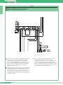
Descrizione morsettiera:
S chiamata elettronica
2 altoparlante
3 microfono
4 comune audio e servizi
P1 pulsante serratura elettrica
P2 pulsante per servizi ausiliari
C comune pulsanti P1-P2
se i pulsanti servono liberi da tensione, tagliare il cavallotto 4-C posto sulla
morsettiera.
C Regolazione volume microfono.
Description of terminal box:
S Electronic call
2 Loudspeaker
3 Microphone
4 Common audio and services
P1 Electric locking button
P2 Button for auxiliary services
C Common buttons P1-P2
If the buttons are required without voltage, cut the 4-C staple located on the
terminal board.
Microphone volume adjustment.
Description du bornier:
S appel électronique
2 haut-parleur
3 microphone
4 commun audio et services
P1 bouton de la serrure électronique
P2 bouton pour services auxiliaires
C commun des boutons P1-P2
si les boutons doivent être utilisés sans tension, coupez le cavalier 4-C
situé sur le bornier.
Réglage volume micro.
I
GB
F
I
GB
F
DESCRIZIONE CITOFONO DA PARETE OKAY E MORSETTIERA
DESCRIPTION OF OKAY WALL-MOUNTED INTERCOM AND
TERMINAL BOARD
DESCRIPTION DE L'INTERPHONE MURAL OKAY ET DU
BORNIER
FI
GB
ISTRUZIONI PER INSTALLAZIONE CITOFONO DA PARETE
OKAY ART. 2402W
INSTRUCTIONS FOR INSTALLING AN OKAY
WALL-MOUNTED INTERCOM ART. 2402W
INSTRUCTIONS D'INSTALLATION DE L'INTERPHONE
MURAL OKAY ART. 2402W
FI
GB
La pagina si sta caricando...
La pagina si sta caricando...
La pagina si sta caricando...
La pagina si sta caricando...
La pagina si sta caricando...
La pagina si sta caricando...
La pagina si sta caricando...
La pagina si sta caricando...
La pagina si sta caricando...
La pagina si sta caricando...
La pagina si sta caricando...
La pagina si sta caricando...
La pagina si sta caricando...
La pagina si sta caricando...
La pagina si sta caricando...
La pagina si sta caricando...
La pagina si sta caricando...
La pagina si sta caricando...
La pagina si sta caricando...
La pagina si sta caricando...
La pagina si sta caricando...
La pagina si sta caricando...
La pagina si sta caricando...
La pagina si sta caricando...
La pagina si sta caricando...
La pagina si sta caricando...
La pagina si sta caricando...
La pagina si sta caricando...
La pagina si sta caricando...
La pagina si sta caricando...
La pagina si sta caricando...
La pagina si sta caricando...
La pagina si sta caricando...
La pagina si sta caricando...
La pagina si sta caricando...
La pagina si sta caricando...
La pagina si sta caricando...
La pagina si sta caricando...
La pagina si sta caricando...
La pagina si sta caricando...
La pagina si sta caricando...
La pagina si sta caricando...
La pagina si sta caricando...
La pagina si sta caricando...
-
 1
1
-
 2
2
-
 3
3
-
 4
4
-
 5
5
-
 6
6
-
 7
7
-
 8
8
-
 9
9
-
 10
10
-
 11
11
-
 12
12
-
 13
13
-
 14
14
-
 15
15
-
 16
16
-
 17
17
-
 18
18
-
 19
19
-
 20
20
-
 21
21
-
 22
22
-
 23
23
-
 24
24
-
 25
25
-
 26
26
-
 27
27
-
 28
28
-
 29
29
-
 30
30
-
 31
31
-
 32
32
-
 33
33
-
 34
34
-
 35
35
-
 36
36
-
 37
37
-
 38
38
-
 39
39
-
 40
40
-
 41
41
-
 42
42
-
 43
43
-
 44
44
-
 45
45
-
 46
46
-
 47
47
-
 48
48
-
 49
49
-
 50
50
-
 51
51
-
 52
52
-
 53
53
-
 54
54
-
 55
55
-
 56
56
-
 57
57
-
 58
58
-
 59
59
-
 60
60
-
 61
61
-
 62
62
-
 63
63
-
 64
64
-
 65
65
-
 66
66
-
 67
67
-
 68
68
-
 69
69
-
 70
70
-
 71
71
-
 72
72
-
 73
73
-
 74
74
-
 75
75
-
 76
76


Videovox Pro GB Series Guida utente
- Categoria
- Videoregistratori digitali (DVR)
- Tipo
- Guida utente
in altre lingue
- English: Videovox Pro GB Series User guide
- français: Videovox Pro GB Series Mode d'emploi
Altri documenti
-
Comelit DiVA Series Technical Sheet
-
-
-
-
Elvox 7200 Series Istruzioni per l'uso
-
-
-
-
CAME DMI Guida d'installazione
-