Rockford Fosgate Punch P1T-S Installation & Operation Manual
- Categoria
- Altoparlanti
- Tipo
- Installation & Operation Manual
Questo manuale è adatto anche per

Serial Number: Date of Purchase:
Installation & Operation
COMPONENT
SPEAKERS
P1T-S
P16-S
P152-S
P1675-S
P165-S

2
Dear Customer,
Congratulations on your purchase of the world’s finest brand of car audio
amplifiers. At Rockford Fosgate we are fanatics about musical reproduc-
tion at its best, and we are pleased you chose our product. Through
years of engineering expertise, hand craftsmanship and critical testing
procedures, we have created a wide range of products that reproduce
music with all the clarity and richness you deserve.
For maximum performance we recommend you have your new Rockford
Fosgate product installed by an Authorized Rockford Fosgate Dealer,
as we provide specialized training through Rockford Technical Training
Institute (RTTI). Please read your warranty and retain your receipt and
original carton for possible future use.
Great product and competent installations are only a piece of the puzzle
when it comes to your system. Make sure that your installer is using
100% authentic installation accessories from Rockford Fosgate in your
installation. Rockford Fosgate has everything from RCA cables and
speaker wire to power wire and battery connectors. Insist on it! After all,
your new system deserves nothing but the best.
To add the finishing touch to your new Rockford Fosgate image order
your Rockford accessories, which include everything from T-shirts to
jackets.
Visit our web site for the latest information on all Rockford products
;
www.rockfordfosgate.com
or, in the U.S. call 1-800-669-9899 or FAX 1-800-398-3985. For all other
countries, call +001-480-967-3565 or FAX +001-480-966-3983.
Table of Content
If, after reading your manual, you still have questions regarding this prod-
uct, we recommend that you see your Rockford Fosgate dealer. If you need
further assistance, you can call us direct at 1-800-669-9899. Be sure to
have your serial number, model number and date of purchase available
when you call.
Safety
This symbol with “WARNING” is intended
to alert the user to the presence of important
instructions. Failure to heed the instructions
will result in severe injury or death.
This symbol with “CAUTION” is intended to
alert the user to the presence of important
instructions. Failure to heed the instructions
can result in injury or unit damage.
sTo prevent injury and damage to the unit, please read and follow the
instructions in this manual. We want you to enjoy this system, not get
a headache.
sIf you feel unsure about installing this system yourself, have it installed
by a qualified Rockford Fosgate technician.
sBefore installation, disconnect the battery negative (-) terminal to
prevent damage to the unit, fire and/or possible injury.
0U[YVK\J[PVU
©2012 Rockford Corporation. All Rights Reversed. ROCKFORD FOSGATE, PUNCH and associated logos where applicable are registered trademarks of Rockford Corporation in
the United States and/or other countries. All other trademarks are the property of their respective owners. Specifications subject to change without notice. For use in vehicles only.
79(*;0*,:(-,:6<5+
Continuous exposure to sound pressure levels over 100dB may cause
permanent hearing loss. High powered auto sound systems may
produce sound pressure levels well over 130dB. Use common sense
and practice safe sound.
79(;08<,A<5,i*6<;,:(5:90:8<,:
Une exposition continue à des niveaux de pression acoustique upérieurs à
100 dB peut causer une perte d’acuité auditive permanente. Les systèmes
audio de forte puissance pour auto peuvent produire des niveaux de
pression acoustique bien au-delà de 130 dB. Faites preuve de bon sens et
pratiquez une écoute sans risques
79(*;08<,,3:650+6:,.<96
El contacto continuo con niveles de presión de sonido superiores a 100
dB puede causar la pérdida permanente de la audición. Los sistemas de
sonido de alta potencia para automóviles pueden producir niveles de
presión de sonido superiores a los 130 dB. Aplique el sentido común y
practique el sonido seguro.
79(2;0A0,9,5:0,:0*/,9,5:6<5+
Fortgesetzte Geräuschdruckpegel von über 100 dB können beim
Menschen zu permanentem Hörverlust führen. Leistungsstarke
Autosoundsysteme können Geräuschdruckpegel erzeugen, die weit über
130 dB liegen. Bitte wenden Sie gesunden Menschenverstand an und
praktizieren Sie sicheren Sound.
6::,9=(;,3,9,.63,+,3:<656:,5A(7,90*630
La costante esposizione a livelli di pressione acustica al di sopra dei
100dB possono causare la perdita permanente dell’udito. I sistemi
audio ad alta potenza possono produrre livelli di pressione acustica ben
superiori ai 130dB. Si consiglia il buon senso e l’osservanza delle regole
del suono senza pericoli
2 Introduction
3-5 Specifications
6-9 Installation
Installation Considerations
Mounting
Wiring
10-11 Additional Languages
French
Spanish
German
Italian
12 Limited Warranty Information

3
:WLJPÄJH[PVUZ
Model
P152-S P16-S P165-S P1675-S P1T-S
Nominal Diameter
5.25”
(133mm)
6”
(153mm)
6.5”
(165mm)
6.75”
(171.5mm)
1.0”
(25mm)
Description 2-Way 2-Way 2-Way 2-Way Tweeter
Nominal Impedance 41 41 41 41 41
Frequency Response 70-22kHz 60-22kHz 60-22kHz 55-22kHz 3.5kHz-22kHz
Voice Coil Diameter
1.0”
(25.4mm)
1.0”
(25.4mm)
1.0”
(25.4mm)
1.0”
(25.4mm)
1.0”
(25.4mm)
Power Rating
(RMS/Peak)
50W / 100W 60W / 120W 60W / 120W 60W / 120W 60W / 120W
Fs -
Free Air Resonance 70 Hz 60 Hz 60 Hz 60 Hz 3.5 kHz
Qts 0.68 0.70 0.70 0.72 N/A
Vas
0.19 ft
3
(5.4L)
0.42 ft
3
(11.8L)
0.42 ft
3
(11.8L)
0.61 ft
3
(17.4L)
N/A
Sensitivity
(1W/1M) 87dB 87.2dB 87.2dB 89dB 90dB
Sensitivity
(2.83V/1M) 90dB 90.2dB 90.2dB 92dB 93dB
Xmax
0.10”
(2.5mm)
0.11”
(2.8mm)
0.11”
(2.8mm)
0.25”
(6.4mm)
N/A
Mounting Diameter
4.81”
(122.2mm)
5.05”
(128.2mm)
5.05”
(128.2mm)
5.68”
(144.2mm)
1.75”
(44.4mm)
Mounting Depth
1.91”
(48.5mm)
1.93”
(49.0mm)
1.93”
(49.0mm)
2.24”
(57.0mm)
0.91”
(23.1mm)
Grille/Trim Ring YES YES YES YES YES
Adaptor Plate YES NO NO NO NO
See pages 4-5 for additional dimensions
CEA 2031
Power handling on Rockford Fosgate speakers conform to CEA-2031 industry standards. This means your speaker has the
capacity to handle power under continuous demand, not instantaneous power handling that over time can damage voice coils.

4
:WLJPÄJH[PVUZ
illus.-1.1

5
:WLJPÄJH[PVUZ
illus.-1.2

6
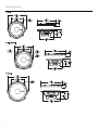
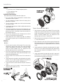
Tweeter - Discreet Dual Clamp (DDC™)
1. Determine where the speakers will be mounted. Ensure an area large
enough for the speaker to mount evenly. Be sure that the mounting
location is deep enough for the speaker to fit; if mounting in a door,
operate all functions (windows, locks, etc.) through their entire
operating range to ensure there is no obstruction.
2. Mark the location for the mounting hole. Drill the hole with a standard
1.75 inch (45mm) hole saw.
3. With a single center screw secure the inner cup from the front of the
door panel to the outer cup from back of the door panel. Tighten the
screw until balanced pressure is applied to both faces of the mounting
surface.
4. Feed the speaker wires through the cutout and connect to the speaker
terminals. Be sure to observe proper polarity when connecting the
wires. The speaker’s lead wires are indicated with a RED wire “+” and
a BLACK wire “-”.
5. Simply snap the tweeter into place and secure with a snap-on trim
ring. Removal is easy if needed. The protective grille on the tweeter is
non-removable and an integral part of the design.
0UZ[HSSH[PVU
Contents
s(1) Pair Punch Series Full Range Component Speakers
s(1) Pair of grilles/trim rings
sMounting Hardware
Installation Considerations
Before beginning any installation, follow these simple rules:
1. Be sure to carefully read and understand the instructions before
attempting to install these speakers.
2. For safety, disconnect the negative lead from the battery prior to
beginning the installation.
3. For easier assembly, we suggest you run all wires prior to mounting
your speakers in place.
4. Use high quality connectors for a reliable installation and to minimize
signal or power loss.
5. Think before you drill! Be careful not to cut or drill into gas tanks, fuel
lines, brake or hydraulic lines, vacuum lines or electrical wiring when
working on any vehicle. If installation in a boat, take care not to cut or
drill through the main hull.
6. Never run wires underneath the vehicle. Running the wires inside the
vehicle or hull area provides the best protection.
7. Avoid running wires over or through sharp edges. Use rubber or
plastic grommets to protect any wires routed through metal, especially
the firewall.
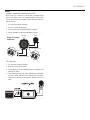
Mounting
Mid-Bass
1. Determine where the speakers will be mounted. Ensure an area large
enough for the speaker to mount evenly. Be sure that the mounting
location is deep enough for the speaker to fit; if mounting in a door,
operate all functions (windows, locks, etc.) through their entire
operating range to ensure there is no obstruction.
2. Refer to the specification chart to determine the proper diameter hole
to cut for your speaker model. Cutting and mounting templates can be
found at www.rockfordfosgate.com.
3. Mark the locations for the mounting screws. Drill the holes with a
1/8” bit.
4. Feed the speaker wires through the cutout and connect to the speaker
terminals. Be sure to observe proper polarity when connecting the
wires.The speaker’s positive terminal is indicated with a “+”.
5. Fit the trim ring over the speaker and mount into place using four (4)
screws.
6. Tighten the screws until the speaker is snug in place to prevent
rattling. Do not over tighten the screws.
illus.-2.2
illus.-2.3
illus.-2.1

7
Wiring
Standard - Integrated Concealed Crossover (ICC™)
NOTE: For the P152-S and P1652-S, the crossover is integrated into the
basket of the mid-bass driver. This component grade crossover allows
for easy connection of the full component system without the need for an
external crossover.
1. Use illustration for proper connection.
2. Be sure to maintain speaker polarity.
3. Connect primary tabs on Mid-Range/Woofer to Amplifier.
4. Connect secondary tabs on Mid-Range/Woofer to Tweeter.
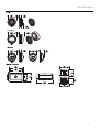
P1T-S Crossover
1. Use illustration for proper connection.
2. Be sure to maintain speaker polarity.
3. Connecting the positive wire to 0dB matches the amplitude of the
tweeter to the speaker.
4. Connecting the positive wire to -2dB or -4dB reduces the amplitude of
the tweeter -2dB or -4dB lower than the midrange, (ideal for tweeters
located high in door panels and midranges located low in the kick
panel).
0UZ[HSSH[PVU
illus.-3.1
illus.-3.2
IN – Connect from Amplifier
TWT – Connect to Tweeter
Mid-Range
Woofer
Tweeter
Example of P1 component
standard wiring

8
0UZ[HSSH[PVU
illus.-4.1
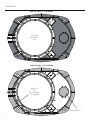
Adapter Plate Template - 6.75” Hole Mounting
Remove Shaded
Areas to Mount 5.25"
(P152-S)
Adapter Plate Template - 6”x9” Hole Mounting
Mounting for 5.25”
(P152-S)
*Remove Light Shaded Areas
for 5”x7” Hole Mounting
*Remove for Optional Tweeter

9
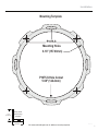
0UZ[HSSH[PVU
illus.-5.1
1.00"
(25.40mm)
Verify Scale
Before Using
Template
1.00"
(25.40mm)
Mounting Template
5.68" (144.2mm)
P1675-S Hole Cutout
P1675-S
Mounting Holes
6.18" (157.00mm)
Visit www.rockfordfosgate.com for additional mounting templates.

10
-YHUsHPZ ,ZWH|VS
Considérations Concernant L’installation
Avant de commencer l’installation, suivez les règles ci-dessous:
1. Veillez à bien lire et comprendre les instructions avant d’essayer d’installer les haut-parleurs.
2. Par mesure de sécurité, débranchez le fil négatif de la batterie avant de commencer l’installation.
3. Pour faciliter le montage des haut-parleurs, il est conseillé d’installer tous les câbles au préalable.
4. Utilisez des connecteurs de haute qualité pour assurer une installation fiable et réduire au minimum
la perte de signal ou de puissance.
5. Réfléchissez bien avant de percer.Veillez à ne pas couper ou percer le réservoir d’essence, le câblage
électrique ou les conduites de carburant, de freinage hydraulique ou de dépression en travaillant
sur un véhicule. En cas d’installation sur un bateau, veillez à ne pas couper ou percer la coque
principale.
6. Ne jamais faire passer de fils sous le véhicule. Leur installation à l’intérieur du véhicule ou de la
coque assure la meilleure protection.
7. Évitez de faire passer des fils sur des bords tranchants ou dans des orifices à arêtes vives. Utilisez
des bagues en caoutchouc ou en plastique pour protéger les fils traversant une plaque de métal,
notamment le tablier.Emplacements De Montage
Montage (illus.-2.1 - 2.3)
Mid-Bass
1. Déterminez l’emplacement des haut-parleurs.Veillez à ce que la surface plane soit assez grande pour
assurer un contact uniforme du haut-parleur.Vérifiez que l’emplacement est assez profond pour le
haut-parleur ; en cas de montage dans une portière, actionnez toutes les commandes (fenêtres,
serrures, etc.) jusqu’aux extrémités de leurs courses pour vous assurer qu’il n’y a pas d’obstruction.
2. Consultez le tableau des caractéristiques pour déterminer le diamètre de l’orifice à découper pour
votre modèle de haut-parleur. Le gabarit fourni donne aussi le bon diamètre de découpe.Les
gabarits de coupe et de montage sont disponibles sur la page www.rockfordfosgate.com/rftech.
3. Marquez l’emplacement des vis de montage. Percez les trous avec une mèche de 1/8 de pouce
(3,2 mm).
4. Faites passer les fils de haut-parleur à travers l’orifice découpé et branchez-les aux bornes du haut-
parleur.Veillez à bien respecter la polarité lors du branchement. La borne positive du haut-parleur
est indiquée par un « + ».
5. Disposez l’anneau de garniture sur le haut-parleur et fixez-le avec quatre (4) vis.
6. Serrez les vis jusqu’à ce que le haut-parleur soit bien ajusté, de façon à prévenir tout cliquetis, mais
évitez tout serrage excessif.
Tweeter - Discreet Dual Clamp (DDC™)
1. Déterminer l’endroit de montage des enceintes. S’assurer que la zone est suffisamment large pour
monter l’enceinte uniformément. S’assurer que l’emplacement de montage est suffisamment profond
pour que l’enceinte y rentre; si on la monte sur une porte, activer toutes les fonctions (fenêtres,
verrous, etc.) dans toute leur plage d’exploitation pour s’assurer qu’il n’y a pas d’obstruction.
2. Marquer l’emplacement du trou de montage. Percer le trou à l’aide d’une scie cloche standard de
45 mm (1,75 po).
3. À l’aide d’une seule vis centrale, sécuriser la coupelle interne du devant du panneau de porte sur
la coupelle externe du dos du panneau de porte. Serrer la vis jusqu’à ce qu’une pression équilibrée
soit appliquée sur les deux faces de la surface de montage.
4. Alimenter les fils d’enceinte à travers la découpe et connecter aux bornes d’enceinte. S’assurer
d’observer la polarité appropriée lors de la connexion des fils. Les fils de l’enceinte sont indiqués
par un fil ROUGE « + » et un fil NOIR « - ».
5. Il suffit d’enclencher le tweeter en place et de sécuriser à l’aide d’une bague de garniture à
enclencher. Si besoin, la dépose est aisée. La grille protectrice sur le tweeter est inamovible et fait
partie intégrale du design.
Câblage (illus.-3.1 & 3.2)
Standard - ICC (Filtre de coupure intégré)
REMARQUE: Pour les modèles P152-s et P1652-S, le filtre de coupure est intégré au haut-parleur, si
bien qu’aucun filtre externe n’est requis. Il vous suffit de connecter les fils du tweeter aux bornes TWT
du haut-parleur.
1. Utiliser l’illustration pour une bonne connexion.
2. Assurez-vous de maintenir orateur polarité.
3. Connectez les onglets primaires sur la mi-portée/woofer à l’amplificateur.
4. Connectez les onglets secondaires sur la mi-portée/woofer au tweeter.
P1T-S Câblage
1. Voir le branchement correct sur l’illustration.
2. Veillez à maintenir la polarité du haut-parleur.
3. Le branchement du fil positif à la borne 0 dB accorde l’amplitude du tweeter sur celle du haut-
parleur.
4. Le branchement du fil positif à la borne -2 dB ou -4 dB réduit l’amplitude du tweeter de -2 ou -4 dB
par rapport à celle du haut-parleur de médium (idéal lorsque les tweeters sont situés en haut des
panneaux de porte et les haut-parleurs de médium dans les panneaux de seuil).
Consideraciones para la instalación
Antes de comenzar cualquier instalación, siga estas simples normas:
1. Asegúrese de leer cuidadosamente y de entender las instrucciones antes de tratar de instalar estos
altavoces.
2. Por seguridad, desconecte el conductor negativo de la batería antes de comenzar la instalación.
3. Para facilitar el montaje, sugerimos que tienda todos los cables antes de montar sus altavoces en
su sitio.
4. Utilice conectores de alta calidad para tener una instalación confiable y para reducir al mínimo las
pérdidas de señal o de potencia.
5. ¡Piense siempre antes de perforar! Tenga cuidado de no cortar ni perforar en tanques de combustible,
tuberías de combustible, frenos o hidráulicas, tuberías de vacío o cableado eléctrico al trabajar en
un vehículo. Si la instalación se hace en un bote, tenga cuidado de no cortar ni perforar a través
del casco principal.
6. Nunca tienda cables abajo del vehículo.Tender los cables adentro del vehículo o casco proporciona
la mejor protección.
7. Evite tender cables arriba o a través de bordes filosos. Use arandelas aislantes de caucho para
proteger los cables tendidos a través de metal, especialmente la mampara cortafuegos.Montage
Montaje (illus.-2.1 - 2.3)
Mid-Bass
1. Determine adónde se montará los altavoces.Asegúrese de que haya un área suficientemente grande
para montar de manera plana el altavoz.Asegúrese de que el lugar de montaje sea suficientemente
profundo para que quepa el altavoz, si se monta en una puerta, accione todas las funciones
(ventanas, cerradura, etc.) en toda su gama de funcionamiento para asegurarse de que no haya
obstrucciones.
2. Consulte la tabla de especificaciones para determinar cuales son los diámetros correctos para el
agujero a cortar para su modelo de altavoz. La plantilla proporcionada también le da la medida
correcta del recorte.Se puede hallar las plantillas para el corte y el montaje en www.rockfordfosgate.
com/rftech.
3. Marque las localidades para los tornillos de montaje. Perfore los agujeros usando una broca de
1/8 pulg.
4. Tienda los cables del altavoz a través del recorte y conecte a los terminales del altavoz.Asegúrese
de usar la polaridad correcta al conectar los cables. El terminal positivo del altavoz está identificado
con un símbolo “+”.
5. Coloque el anillo de acabado arriba del altavoz y móntelo en su sitio usando cuatro (4) tornillos.
6. Apriete los tornillos hasta que el altavoz esté ajustado en su sitio para evitar vibraciones. No apriete
demasiado los tornillos.
Tweeter - Abrazadera Discreet Dual Clamp (DDC™)
1. Determine adónde se montarán los altavoces. Asegúrese de que haya un área suficientemente
grande para montar de manera uniforme el altavoz. Asegúrese de que el lugar de montaje sea
suficientemente profundo para que quepa el altavoz, si se monta en una puerta, accione todas las
funciones (ventanas, cerradura, etc.) en toda su gama de funcionamiento para asegurarse de que
no haya obstrucciones.
2. Marque las localidades para el agujero de montaje. Haga un agujero usando una sierra para
agujeros estándar de 45mm (1.75 pulgadas).
3. Con un solo tornillo central, asegure la taza interna de la parte delantera del panel de la puerta a la
taza externa de la parte posterior del panel de la puerta. Apriete el tornillo hasta que se aplique una
presión equilibrada a ambas caras de la superficie de montaje.
4. Tienda los cables del altavoz a través del recorte y conecte a los terminales del altavoz. Asegúrese
de usar la polaridad correcta al conectar los cables. Los cables del altavoz están identificados con
un cable ROJO “+” y un cable NEGRO “-”.
5. Simplemente presione el tweeter en su sitio ya asegúrelo con un anillo de acabado a presión. Es
fácil extraerlo si es necesario. La rejilla protectora en el tweeter no se puede extraer y es una parte
integral del diseño.
Cableado (illus.-3.1 & 3.2)
Estándar - ICC (Cruce encubierta integrada)
NOTA: Para el P152-s y el P1652-S, el cruce es un diseño integral del altavoz. Por lo tanto, no se necesita
un cruce externo. Simplemente conecte los cables del tweeter a los terminales TWT en el altavoz.
1. Utilice la ilustración para una correcta conexión.
2. Asegúrese de mantener la polaridad de los altavoces.
3. Conecte las tabulaciones primarias en alcance medio/el altavoz para bajas audiofrecuencias con
el amplificador.
4. Conecte las tabulaciones secundarias en alcance medio/el altavoz para bajas audiofrecuencias con
el altavoz de agudos.
P1T-S Estándar
1. Utilice la ilustración para hacer una conexión correcta.
2. Asegúrese de mantener la polaridad del altavoz.
3. Conectar el cable positivo a 0dB hace que coincida la amplitud del tweeter con el altavoz.
4. Conectar el cable positivo a -2dB o -4dB reduce la amplitud del tweeter -2dB o -4dB menos que la
gama de medias, (ideal para tweeters situados altos en paneles de puertas y de frecuencias medias
sitiados bajos en la placa de defensa).

11
+L\[ZJO 0[HSPHUV
Einbauüberlegungen
Befolgen Sie vor dem Einbau diese einfachen Regeln:
1. Lesen Sie die Anleitung sorgfältig, bevor Sie versuchen diese Lautsprecher einzubauen.
2. Entfernen Sie vor dem Einbau aus Sicherheitsgründen das negative Kabel von der Batterie.
3. Um die Montage zu erleichtern, empfehlen wir alle Kabel vor der Befestigung Ihrer Lautsprecher
zu verlegen.
4. Verwenden Sie nur Qualitätsstecker, um einen zuverlässigen Einbau zu gewährleisten und Signal-
und Stromverlust zu minimieren.
5. Denken Sie nach, bevor Sie bohren! Achten Sie darauf, nicht in den Benzintank, die Benzin-,
Brems- oder hydraulischen Leitungen,Vakuumleitungen oder Elektrokabel zu schneiden oder zu
bohren,wenn Sie am Fahrzeug arbeiten.Achten Sie beim Einbau in einem Boot darauf, nicht durch
den Bootsrumpf zu schneiden oder zu bohren.
6. Verlegen Sie Kabel nie unter dem Fahrzeug. Die Kabel im Fahrzeug oder Bootsrumpf zu verlegen,
bietet den besten Schutz.
7. Vermeiden Sie es, Kabel über scharfe Kanten zu verlegen.Verwenden Sie Gummi- oder Plastikringe,
um Kabel zu schützen, die durch Metall verlegt werden (besonders die Feuerwand).
Befestigung (illus.-2.1 - 2.3)
Mid-Bass
1. Entscheiden,wo die Lautsprecher befestigt werden sollen. Gewährleisten, dass der Platz ausreicht,
um den Lautsprecher gleichmäßig zu befestigen. Gewährleisten, dass die Befestigungsstelle
ausreichende Tiefe für den Lautsprecher hat; beim Einbau in einer Türe alle Funktionen (Fenster,
Schloss usw.) in ihrem ganzen Bereich ausprobieren um zu gewährleisten, dass keine Blockierung
eintritt.
2. Die Tabelle in den Technischen Daten gibt den richtigen Lochdurchmesser für Ihr Lautsprechermodell
zum Ausschneiden an. Die beiliegende Schablone zeigt ebenfalls die richtige Ausschneidegröße
an.Schneide- und Befestigungsschablonen finden Sie unter www.rockfordfosgate.com/rftech.
3. Die Stellen für die Befestigungsschrauben markieren. Die Löcher mit einer 1/8-Zoll (3,2 mm)
Bohrerspitze bohren.
4. Die Lautsprecherkabel durch das Loch führen und an den Lautsprecherausgängen anschließen.
Beim Anschließen der Kabel die ordnungsgemäße Polarität beachten. Der positive Anschluss des
Lautsprechers ist mit einem „+“ markiert.
5. Den Zierring über den Lautsprecher legen und mit 4 (vier) Schrauben an seinem Platz befestigen.
6. Die Schrauben anziehen, bis der Lautsprecher eng an seinem Platz anliegt, um Klappern zu
verhindern. Die Schrauben nicht zu fest anziehen.
Hochtöner - Discreet Dual Clamp (DDC™)
1. Entscheiden, wo die Lautsprecher befestigt werden sollen. Gewährleisten, dass der Platz ausreicht,
um den Lautsprecher gleichmäßig zu befestigen. Gewährleisten, dass die Befestigungsstelle
ausreichende Tiefe für den Lautsprecher hat; beim Einbau in einer Türe alle Funktionen (Fenster,
Schloss usw.) in ihrem ganzen Bereich ausprobieren um zu gewährleisten, dass keine Blockierung
eintritt.
2. Die Stelle für das Befestigungsloch markieren. Das Loch mit einer 1,75-Zoll (45 mm)
Standardlochsäge bohren.
3. Das Innengefäß von der Vorderseite des Türpaneels mit einer einzigen Mittelschraube am
Außengefäß von der Rückseite des Türpaneels befestigen. Die Schraube anziehen, bis gleichmäßiger
Druck auf beide Flächen der Befestigungsoberfläche ausgeübt wird.
4. Die Lautsprecheradern durch das Loch führen und an den Lautsprecherausgängen anschließen.
Beim Anschließen der Kabel die ordnungsgemäße Polarität beachten. Das Lautsprecherkabel hat
eine ROTE Ader, die mit „+“, und eine SCHWARZE Ader, die mit „-“ markiert ist.
5. Den Hochtöner einfach an seinem Platz einschnappen lassen und mit einem Schnappzierring
befestigen. Das Entfernen, falls erforderlich, ist einfach. Das Schutzgitter auf dem Hochtöner kann
nicht entfernt werden und ist ein integraler Teil des Designs.
Verkabelung (illus.-3.1 & 3.2)
Standard - ICC (Integrierter verborgener Crossover)
HINWEIS: Bei den Modellen P152-s und P1652-s ist das Crossover ein integrales Design des Lautsprech-
ers. Daher wird ein externes Crossover nicht benötigt. Einfach die Drähte vom Hochtöner an den TWT-
Anschlüssen am Lautsprecher anschließen.
1. Verwenden Sie für die richtige Verbindung Illustration.
2. Stellen Sie sicher, dass die Aufrechterhaltung Lautsprecher Polarität.
3. Schließen Sie Primärtabulatoren auf Mittelbereich/Woofer an Verstärker an.
4. Schließen Sie Sekundärtabulatoren auf Mittelbereich/Woofer an Tweeter an.
P1T-S Verkabelung
1. Zum ordnungsgemäßen Anschließen die Illustration benutzen.
2. Dabei die Lautsprecherpolarität beachten.
3. Das Anschließen des positiven Drahts an 0 dB stimmt die Amplitude des Hochtöners auf den
Lautsprecher ab.
4. Das Anschließen des positiven Drahts an -2dB oder -4dB reduziert die Amplitude des Hochtöners
auf -2dB oder -4dB niedriger als den Mitteltöner (ideal für Hochtöner, die sich hoch in Türpaneelen
befinden, und Mitteltöner, die sich tief im Fußpaneel befinden).
Considerazioni sull’installazione
Prima di iniziare qualsiasi operazione d’installazione, vi consigliamo di seguire queste semplici regole:
1. Assicuratevi di aver letto tutte le istruzioni con cura e di averle capite prima di effettuare qualsiasi
tentativo d’installazione neiconfronti dell’unità.
2. Per motivi di sicurezza, scollegate il cavo negativo dalla batteria prima di dare l’avvìo all’installazione.
3. Per facilitare il montaggio, vi suggeriamo di far scorrere tutti i fili prima di montare la vostra unità
nella sua ubicazione.
4. Usate connettori di alta qualità per garantire un’installazione che dà affidamento e per ridurre al
minimo la perdita di segnali o di potenza.
5. State attenti prima di trapanare! Cercate di non trapanare e di non incidere i serbatoi della benzina;
le condutture del carburante, dei freni, del sistema idraulico e a depressione; nonché i fili elettrici
quando state lavorando su qualsiasi veicolo.
6. Non fate mai scorrere i fili sotto il veicolo.Avrete la protezione migliore faccendo scorrere i fili
all’interno del veicolo.
7. Evitate di far scorrere i fili sopra o attraverso delle estremità affilate. Usate guarnizioni di tenuta in
gomma o in plastica per proteggere qualsiasi filo che passi attraverso del metallo, soprattutto il
parafiamma.
Montaggio (illus.-2.1 - 2.3)
Mid-Bass
1. Decidete dove montare gli altoparlanti.Assicuratevi che sia un’area abbastanza grande per poter
montare l’altoparlante a livello e abbastanza profonda per poterlo collocare comodamente. Se lo
montate all’interno di uno sportello, controllate tutte le funzioni (finestre, serrature, ecc.), una alla
volta, per assicurarvi che non ci siano ostruzioni.
2. Fate riferimento alla tabella delle specifiche per stabilire il diametro corretto del foro che dovrete
praticare per il modello del vostro altoparlante.Si possono trovare le sagome per il taglio e il
montaggio presso www.rockfordfosgate.com/rftech.
3. Marcare le posizioni per le viti di montaggio. Praticare i fori con una punta da trapano di 1/8 di
pollice (3,2 mm).
4. Passare i cavi del diffusore tramite l’apertura e collegarli ai terminali.Verificare che la polarità sia
corretta quando si collegano i cavi. Il terminale positivo del diffusore è identificato dal “+”.
5. Adattare l’anello di finitura sul diffusore e montare in posizione servendosi delle quattro (4) viti.
6. Per evitare rumore dovuto a vibrazioni serrare le viti finché il diffusore non sia saldamente in
posizione. Non serrare le viti in modo eccessivo.
Tweeter - Discreet Dual Clamp (DDC™)
1. Stabilire in quale posizione montare i diffusori. Accertarsi che l’area sia sufficientemente spaziosa
per montare i diffusori in modo uguale. Accertarsi che il luogo di montaggio sia profondo
a sufficienza per il diffusore; quando si monta su una portiera, controllare che tutte le funzioni
(finestre, serrature, ecc.) funzionino liberamente senza ostruzioni.
2. Marcare la posizione per le viti di montaggio. Praticare il foro servendosi di una sega frontale a
corona standard della misura di 1,75 pollici (45 mm).
3. Utilizzando una vite a centro unico, fissare la coppa interna dal pannello anteriore della porta alla
coppa esterna, dalla parte posteriore del pannello della porta. Serrare la vite sino a quando la
pressione su entrambi i lati della superficie di montaggio non è equilibrata.
4. Passare i fili del diffusore nel foro e collegarli ai terminali del diffusore. Quando si esegue
la connessione, accertarsi di osservare la polarità corretta. I fili conduttori dei diffusori sono
rappresentati da un filo ROSSO “+” e da un filo NERO “-“.
5. Basta fare scattare il tweeter in posizione e fissare con l’anello di rifinitura a scatto. Se si rende
necessario, toglierlo è facile. La griglia di protezione sul tweeter non è rimovibile e costituisce una
parte integrale del design.
Collegamento fili (illus.-3.1 & 3.2)
Standard - ICC (Crossover celato integrato)
NOTA: Per progettazione, il crossover del P152 e del P1652-S è incorporato nel diffusore. Pertanto non
si richiede l’uso di un crossover esterno. Basta collegare i fili provenienti dal tweeter ai terminali TWT
sul diffusore.
1. Usa illustrazione per la corretta connessione.
2. Ricordati di mantenere la polarità dei diffusori.
3. Connetta le tabulazione primarie sulla media scadenza/Woofer all’amplificatore.
4. Connetta le tabulazione secondarie sulla media scadenza/Woofer al Tweeter.
P1T-S Collegamento fili
1. Per il collegamento corretto riferirsi all’illustrazione.
2. Accertarsi di mantenere la polarità del diffusore.
3. Il collegamento del filo del positivo a 0dB fa corrispondere l’ampiezza del tweeter al diffusore.
4. Il collegamento del filo del positivo a -2dB o - 4dB riduce l’ampiezza del tweeter di -2dB o -4dB al
disotto del midrange (particolarmente indicato per tweeter posti in alto nei pannelli della portiera e
per midrange posti in basso nel kick panel).

12
Rockford Corporation offers a limited warranty on Rockford Fosgate products on the following terms:
Length of Warranty
POWER Amplifiers – 2 Years
PUNCH, PRIME, Marine Amplifiers – 1 Years
All Speakers, Signal Processors, Accessories and Capacitors – 1 Year
Marine Electronics – 1 Year
Any Factory Refurbished Product – 90 days (receipt required)
What is Covered
This warranty applies only to Rockford Fosgate products sold to consumers by Authorized Rockford Fosgate Dealers in the United States of America or its
possessions. Product purchased by consumers from an Authorized Rockford Fosgate Dealer in another country are covered only by that country’s Distribu-
tor and not by Rockford Corporation.
Who is Covered
This warranty covers only the original purchaser of Rockford product purchased from an Authorized Rockford Fosgate Dealer in the United States. In order
to receive service, the purchaser must provide Rockford with a copy of the receipt stating the customer name, dealer name, product purchased and date of
purchase.
Products found to be defective during the warranty period will be repaired or replaced (with a product deemed to be equivalent) at Rockford’s discretion.
What is Not Covered
1. Damage caused by accident, abuse, improper operations,water, theft, shipping.
2. Any cost or expense related to the removal or reinstallation of product.
3. Service performed by anyone other than Rockford or an Authorized Rockford Fosgate Service Center.
4. Any product which has had the serial number defaced, altered, or removed.
5. Subsequent damage to other components.
6. Any product purchased outside the U.S.
7. Any product not purchased from an Authorized Rockford Fosgate Dealer.
Limit on Implied Warranties
Any implied warranties including warranties of fitness for use and merchantability are limited in duration to the period of the express warranty set forth
above. Some states do not allow limitations on the length of an implied warranty, so this limitation may not apply. No person is authorized to assume for
Rockford Fosgate any other liability in connection with the sale of the product.
How to Obtain Service
Contact the Authorized Rockford Fosgate Dealer you purchased this product from. If you need further assistance, call 1-800-669-9899 for Rockford Cus-
tomer Service. You must obtain an RA# (Return Authorization number) to return any product to Rockford Fosgate. You are responsible for shipment of
product to Rockford.
EU Warranty
This product meets the current EU warranty requirements, see your Authorized dealer for details.
>HYYHU[`

Installation assistance availible at:
www.rockfordfosgate.com/rftech
ROCKFORDFOSGATE.COM
3OUTH2OCKFORD$RIVEs4EMPE!RIZONA5NITED3TATES
$IRECTs4OLL&REE
Prin
ted
in
C
hin
a
0
4
03
12B
C
F12
30
-
5
741
3
-
0
1
-
 1
1
-
 2
2
-
 3
3
-
 4
4
-
 5
5
-
 6
6
-
 7
7
-
 8
8
-
 9
9
-
 10
10
-
 11
11
-
 12
12
-
 13
13


Rockford Fosgate Punch P1T-S Installation & Operation Manual
- Categoria
- Altoparlanti
- Tipo
- Installation & Operation Manual
- Questo manuale è adatto anche per
in altre lingue
- English: Rockford Fosgate Punch P1T-S
- français: Rockford Fosgate Punch P1T-S
- español: Rockford Fosgate Punch P1T-S
- Deutsch: Rockford Fosgate Punch P1T-S
Documenti correlati
-
Rockford Fosgate Punch P152-S Installation & Operation Manual
-
 Rockford Fosgate Punch P162S Manuale utente
-
Rockford Fosgate R152-S Manuale utente
-
 Rockford Fosgate P152-S Manuale utente
-
Rockford Fosgate Punch P152-S Installation & Operation Manual
-
Rockford Fosgate Prime R14X2 Manuale del proprietario
-
 Rockford Fosgate T3652-S Installation & Operation Manual
-
Rockford Fosgate R1T-S Manuale utente
-
Rockford Fosgate Punch P152-S Manuale del proprietario
-
Rockford Fosgate Punch P152 Installation & Operation Manual


Altri documenti
-
 punch P165-SI Installation & Operation Manual
-
Prime RM1652 Installation & Operation Manual
-
APC P1-IT Scheda dati
-
-
Audio Design T265-S Manuale del proprietario
-
-
Rockford T1T-S Manuale del proprietario
-
Rockford P165 specificazione
-
-
 ICC ICMPP24CP6 Scheda dati

