Hikoki P14DSL Manuale utente
- Categoria
- Utensili elettrici
- Tipo
- Manuale utente
Questo manuale è adatto anche per

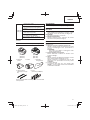
Cordless Planer
Akku Hobel
Rabot sans-fi l
Pialla a batteria
Snoerloze schaafmachine
Cepillo a batería
Plaina a batería
P 14DSL
•
P 18DSL
Handling instructions
Bedienungsanleitung
Mode d’emploi
Istruzioni per l’uso
Gebruiksaanwijzing
Instrucciones de manejo
Instruções de uso
Read through carefully and understand these instructions before use.
Diese Anleitung vor Benutzung des Werkzeugs sorgfältig durchlesen und verstehen.
Lire soigneusement et bien assimiler ces instructions avant usage.
Prima dell’uso leggere attentamente e comprendere queste instruzioni.
Deze gebruiksaanwijzing s.v.p. voor gebruik zorgvuldig doorlezen.
Leer cuidadosamente y comprender estas instrucciones antes del uso.
Antes de usar, leia com cuidado para assimilar estas instruções.
P 18DSL

123
456
789
10 11 12
2
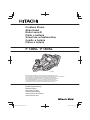
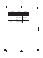
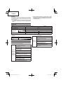
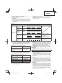
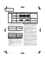
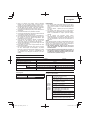
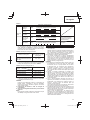
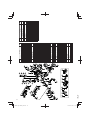
82 mm (Max)
9 mm (Max)
9 mm (Max)
1
2
4
3
9
8
7
6
5
!
@6
5
5
%
^
$
#
& *
q
(
)
w e
0

13 14 15
16 17 18
19 20 21
22 23 24
o
3
r
t
y
u
i
u
o
i
p
p
p
a
d
s
f
f
g
h
o
z
j

25 26 27
28 29 30
31 32 33
34 35 36
4
h
k
k
1mm
1mm
a
a
f
d
l
s
3.5 mm
24.5 mm
;
v
x
z
c
c
n
b
i
i
l
l
l
f
g

37 38 39
5
11 mm
4 mm
,
.
m
¡
/

English Deutsch Français Italiano
1
Planing Hobeln Rabotage Piallatura
2
Beveling Abkanten Biseautage Smussatura
3
Rabberting Falzen Formation de feuillure Scanalatura
4
Tapering Abschrägen Formation de biais Rastrematura
5
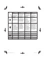
Rechargeable battery Akkumulator Batterie rechargeable Batteria ricaricabile
6
Latch Schnapper Loquet Fermo
7
Battery cover Batterieabdeckung Couvercle de batterie Coperchio per la batteria
8
Terminals Anschlüsse Bornes Terminali
9
Ventilation holes Belüftungslöcher Orifi ces de ventilation Fori di ventilazione
0
Push Drücken Pousser Spingere
!
Pull out Herausziehen Tirer Estrarre
@
Handle Griff Poignée Impugnatura
#
Charger Ladegerät Chargeur Caricatore
$
Pilot lamp Kontrollampe Lampe témoin Spia
%
Switch lock Schalterverriegelung Verrou d’interrupteur Bloqueo del interruptor
^
Switch trigger Abzugschalter Gâchette Interruttore a grilletto
&
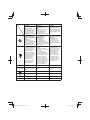
Remaining battery
indicator switch
Ladezustand-
Anzeigeschalter
Commutateur de
puissance batterie
résiduelle
Interruttore indicatore
batteria restante
*
Remaining battery
indicator lamp
Ladezustand-
Kontrollleuchte
Témoin lumineux de
puissance batterie résiduelle
Spia luminosa batteria
restante
(
Knob Knopf Bouton Manopola
)
Scale Skala Échelle Scala graduata
q
Mark Markierung Marque Segno
w
Beginning of cutting
operation
Beginn des Hobelns
Début de l’opération de
coupe
Inizio dell’operazione di
piallatura
e
End of cutting operation Ende des Hobelns Fin de l’opération de coupe
Termine dell’operazione di
piallatura
r
Stand Ständer Support Supporto
t
Set screw Stellschraube Boulon d’ajustement Vite di fi ssaggio
y
Guide Führung Pièce de guidage Guida
u
Box wrench Steckschlüssel Clef à béquille Chiave fi ssa a collare
i
Blade holder Hobeleisenhalter Support de lame Porta-lama
o
Carbide blade
(Double edged blade type)
Hobeleisen mit
Hartmetallschneide
(Beidseitigen klingentyp)
Lame au carbure
(Lames à deux tranchants)
Lama in carburo
(tipo lama a doppio fi lo)
p
Set plate (B) Einstellplatte (B) Plaque de fi
xation (B) Piastra di impostazione (B)
a
Bolt Schraube Boulon Bulloni
s
Machine screw Maschinenschraube Vis machine Vite
d
Turned surface Gebogene Oberfl äche Surface tournée Superfi cie curva
f
Set plate (A) Einstellplatte (A) Plaque de fi xation (A) Piastra di impostazione (A)
g
Set gauge Einstell-Lehre Jauge de fi xation Calibro di impostazione
h
Wall surface b Wandoberfl äche b Surface du mur b Superfi cie parete b
j
Flat portion of the cutter
block
Flacher Teil des
Schneidblocks
Section plate du bloc de
lame
Parte piatta del blocco
taglierina
k
Groove Nut Encoche Scanalatura
l
Blade
(Resharpenable blade type)
Hobeleisen
(schärfbarer Klingentyp)
Lame
(lame de type réaff ûtable)
Lama (tipo lama riaffi labile)
;
Cutter block Schneidblock Bloc de coupe Blocco della pialla
6

English Deutsch Français Italiano
z
Wall surface a Wandoberfl äche a Surface du mur a Superfi cia parete a
x
Chip cover Spanabdeckung Écran anti-copeaux Coperchio trucioli
c
Screw D4 × 16 Schraube D4 × 16 Vis D4 × 16 Vite D4 × 16
v
Dust adapter Staubadapter Adaptateur anti-poussière Adattatore polvere
b
Elbow Knie Coude Gomito
n
Dust bag Staubbeutel Sac à poussière Sacchetto raccoglipolvere
m
Wear limit Verschleißgrenze Limite d’usure Limite di usura
,
Nail of carbon brush Klaue der Kohlebürste Clou de balai en carbone
Chiodo di spazzola di
carbone
.
Protrusion of carbon brush Krempe der Kohlebürste Saillie de balai en carbone
Sporgenza di spazzola di
carbone
/
Brush cap Motorsensenaufsatz Bouchon de porte-balai Coperchio della spazzola
¡
Contact portion outside
brush tube
Kontaktteil außerhalb des
Bürstenrohrs
Section de contact à
l’extérieur du tube de balai
Parte di contatto fuori dal
tubo spazzola
7

Nederlands Español Português
1
Schaven Cepillar
Aplainamento
2
Afbramen Biselar
Chanfragem
3
Groeven Ensamblar
Ranhuragem
4
Afschuinen Renatar
Estreitamento
5
Oplaadbare batterij Batería recargable
Bateria de recarregável
6
Vergrendeling Enganche
Lingüeta
7
Batterijdeksel Tapa de batería
Tampa da bateria
8
Aansluitpunten Terminales
Terminais
9
Ventilatieopeningen Orifi cios de ventilación
Orifícios de ventilação
0
Drukken Presionar
Apertar
!
Uittrekken Sacar
Retirar
@
Handgreep Mango
Cabo
#
Acculader Cargador
Carregador
$
Controlelampje Lámpara piloto
Lâmpada piloto
%
Vergrendeling Bloqueo del interruptor
Bloqueio do interruptor
^
Trekkerschakelaar Interruptor de gatillo
Gatilho do interruptor
&
Indicatieschakelaar
resterende acculading
Interruptor de indicador de
batería restante
Interruptor de indicação da
autonomia da pilha
*
Indicatielampje resterende
acculading
Indicador luminoso batería
restante
Luz de indicação da
autonomia da pilha
(
Knop Botón
Manípulo
)
Schaal Escala
Escala
q
Merkteken Marca
Marca
w
Begin van het schaven
Principio de la operación
de corte
Início da operação de corte
e
Einde van het schaven
Fin de la operación de
corte
Fim da operação de corte
r
Standaard Base
Suporte
t
Stelschroef Tornillo de sujeción
Parafuso de ajuste
y
Geleider Guía
Guia
u
Steeksleutel Llave anular
Chave de bocas
i
Schaafi jzerhouder Sujetador de cuchilla
Suporte da lâmina
o
Koolstofmetaalmes
(Mes met dubbele rand)
Cuchilla de carburo
(Tipo de cuchilla de doble
borde)
Lâmina de carboneto
(Tipo de lâmina de fi o
duplo)
p
Gemonteerde plaat (B) Placa de ajuste (B)
Placa do conjunto (B)
a
Schroef Perno
Parafuso
s
Machineschroef Tornillo de máquina
Parafuso da máquina
d
Gedraaid oppervlak Superfi cie girada
Superfície torneada
f
Gemonteerde plaat (A) Placa de ajuste (A)
Placa do conjunto (A)
g
Gemonteerd meetinstrument
Manómetro de ajuste
Manómetro do conjunto
h
Muuroppervlak b Superfi cie de pared b
Superfície de parede b
j
Vlakke gedeelte van
freeszwart
Parte plana del bloque del
cortador
Parte plana do bloco
cortador
k
Groef Ranura
Ranhura
l
Mes (Slijpbaar mes)
Cuchilla
(Tipo de cuchilla afi lable)
Lâmina
(Tipo de lâmina possível
de afi ar)
;
Snijkop Bloque del cortador
Bloco cortador
8

Nederlands Español Português
z
Muuroppervlak a Superfi cie de pared a
Superfície de parede a
x
Spaankast Cubierta de virutas
Tampa de aparas
c
Schroef D4 × 16 Tornillo D4 × 16
Parafuso D4 × 16
v
Stofadapter Adaptador para el polvo
Adaptador para pó
b
Elleboogstuk Codo
Cotovelo
n
Stofzak Bolsa para el polvo
Saco para pó
m
Slijtagegrens Límite de uso
Limite de desgaste
,
Nagel van koolborstel
Uña de escobilla de
carbón
Prego da escova de
carvão
.
Uitsteeksel van koolborstel
Saliente de escobilla de
carbón
Saliência da escova de
carvão
/
Borstelkap Tapa del cepillo
Tampa da roçadora
¡
Contact-gedeelte buiten de
borstelbuis
Tubo exterior de la parte
de contacto de la escobilla
de carbón
Segmento de contato no
exterior do tubo da escova
9

10
English Deutsch Français Italiano
Symbols
WARNING
The following show
symbols used for the
machine. Be sure that
you understand their
meaning before use.
Symbole
WARNUNG
Die folgenden Symbole
werden für diese Maschine
verwendet. Achten Sie
darauf, diese vor der
Verwendung zu verstehen.
Symboles
AVERTISSEMENT
Les symboles suivants
sont utilisés pour l’outil.
Bien se familiariser avec
leur signifi cation avant
d’utiliser l’outil.
Simboli
AVVERTENZA
Di seguito mostriamo
i simboli usati per la
macchina. Assicurarsi di
comprenderne il signifi cato
prima dell’uso.
Read all safety
warnings and all
instructions.
Failure to follow the
warnings and instructions
may result in electric
shock, fi re and/or serious
injury.
Lesen Sie sämtliche
Sicherheitshinweise und
Anweisungen durch.
Wenn die Warnungen
und Anweisungen nicht
befolgt werden, kann es
zu Stromschlag, Brand
und/oder ernsthaften
Verletzungen kommen.
Lire tous les
avertissements de
sécurité et toutes les
instructions.
Tout manquement
à observer ces
avertissements et
instructions peut engendrer
des chocs électriques,
des incendies et/ou des
blessures graves.
Leggere tutti gli
avvertimenti di
sicurezza e tutte le
istruzioni.
La mancata osservanza
degli avvertimenti e
delle istruzioni potrebbe
essere causa di scosse
elettriche, incendi e/o
gravi lesioni.
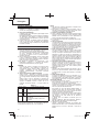
Only for EU countries
Do not dispose of electric tools
together with household waste
material!
In observance of European
Directive 2002/96/EC
on waste electrical and
electronic equipment and its
implementation in accordance
with national law, electric tools
that have reached the end
of their life must be collected
separately and returned to an
environmentally compatible
recycling facility.
Nur für EU-Länder
Werfen Sie Elektrowerkzeuge
nicht in den Hausmüll!
Gemäss Europäischer
Richtlinie 2002/96/EG über
Elektro- und Elektronik-
Altgeräte und Umsetzung
in nationales Recht müssen
verbrauchte Elektrowerkzeuge
getrennt gesammelt und
einer umweltgerechten
Wiederververtung zugeführt
werden.
Pour les pays européens
uniquement
Ne pas jeter les appareils
électriques dans les ordures
ménagères!
Conformément à la directive
européenne 2002/96/
EG relative aux déchets
d’équipements électriques ou
électroniques (DEEE), et à sa
transposition dans la législation
nationale, les appareils
électriques doivent être
collectés à part et être soumis
à un recyclage respectueux de
l’environnement.
Solo per Paesi UE
Non gettare le apparecchiature
elettriche tra i rifi uti domestici.
Secondo la Direttiva Europea
2002/96/CE sui rifi uti di
apparecchiature elettriche ed
elettroniche e la sua attuazione
in conformità alle norme
nazionali, le apparecchiature
elettriche esauste devono
essere raccolte separatamente,
al fi ne di essere reimpiegate in
modo eco-compatibile.
n
0
no-load speed Leerlaufdrehzahl Vitesse à vide Velocità a vuoto
/min or min
-
1
Revolutions or
reciprocations per minute
Umdrehungen oder
Pendelbewegungen pro
Minute
Tours ou mouvements
alternatifs par minute
Rivoluzioni o
reciprocazioni per minuto
Direct current Gleichstrom Courant continu Corrente diretta
Caution Achtung Attention Attenzione
V
Volts Volt Volts Volt
kg
Kilograms Kilogramm Kilogrammes Kilogrammi

11
Nederlands Español Português
Symbolen
WAARSCHUWING
Hieronder staan
symbolen afgebeeld die
van toepassing zijn op
deze machine. U moet
de betekenis hiervan
begrijpen voor gebruik.
Símbolos
ADVERTENCIA
A continuación se
muestran los símbolos
usados para la
máquina. Asegúrese
de comprender su
signifi cado antes del uso.
Símbolos
AVISO
A seguir aparecem os
símbolos utilizados pela
máquina. Assimile bem
seus signifi cados antes
do uso.
Lees alle
waarschuwingen en
instructies aandachtig
door.
Nalating om de
waarschuwingen en
instructies op te volgen
kan in een elektrische
schok, brand en/of
ernstig letsel resulteren.
Lea todas las
instrucciones y
advertencias de
seguridad.
Si no se siguen
las advertencias e
instrucciones, podría
producirse una descarga
eléctrica, un incendio y/o
daños graves.
Leia todas as
instruções e avisos de
segurança.
Se não seguir todas
as instruções e os
avisos, pode provocar
um choque eléctrico,
incêndio e/ou ferimentos
graves.
Alleen voor EU-landen
Geef elektrisch gereedschap
niet met het huisvuil mee!
Volgens de Europese richtlijn
2002/96/EG inzake oude
elektrische en elektronische
apparaten en de toepassing
daarvan binnen de nationale
wetgeving, dient gebruikt
elektrisch gereedschap
gescheiden te worden
ingezameld en te worden
afgevoerd naar een recycle
bedrijf dat voldoet aan de
geldende milieu-eisen
.
Sólo para países de la Unión
Europea
¡No deseche los aparatos
eléctricos junto con los residuos
domésticos!
De conformidad con la
Directiva Europea 2002/96/
CE sobre residuos de aparatos
eléctricos y electrónicos y su
aplicación de acuerdo con
la legislación nacional, las
herramientas eléctricas cuya
vida útil haya llegado a su fi n se
deberán recoger por separado
y trasladar a una planta de
reciclaje que cumpla con las
exigencias ecológicas.
Apenas para países da UE
Não deite ferramentas
eléctricas no lixo doméstico!
De acordo com a directiva
europeia 2002/96/CE sobre
ferramentas eléctricas e
electrónicas usadas e a
transposição para as leis
nacionais, as ferramentas
eléctricas usadas devem
ser recolhidas em separado
e encaminhadas a uma
instalação de reciclagem dos
materiais ecológica.
n
0
snelheid onbelast velocidad sin carga velocidade sem carga
/min or min
-
1
Toerental of heen-enweer
gaande beweging per
minuut.
Revoluciones o giros por
minuto
Rotações ou alternações
por minuto
Gelijkstroom Corriente continua Corrente contínua
Voorzichtig Precaución Atenção
V
Volt Voltios Volts
kg
Kilogram Kilogramos Quilogramas

English
12
GENERAL POWER TOOL SAFETY WARNINGS
WARNING
Read all safety warnings and all instructions.
Failure to follow the warnings and instructions may result in
electric shock, fi re and/or serious injury.
Save all warnings and instructions for future reference.
The term “power tool” in the warnings refers to your mains-
operated (corded) power tool or battery-operated (cordless)
power tool.
1) Work area safety
a) Keep work area clean and well lit.
Cluttered or dark areas invite accidents.
b) Do not operate power tools in explosive
atmospheres, such as in the presence of
fl ammable liquids, gases or dust.
Power tools create sparks which may ignite the dust
or fumes.
c) Keep children and bystanders away while
operating a power tool.
Distractions can cause you to lose control.
2) Electrical safety
a) Power tool plugs must match the outlet.
Never modify the plug in any way.
Do not use any adapter plugs with earthed
(grounded) power tools.
Unmodifi ed plugs and matching outlets will reduce
risk of electric shock.
b) Avoid body contact with earthed or grounded
surfaces, such as pipes, radiators, ranges and
refrigerators.
There is an increased risk of electric shock if your
body is earthed or grounded.
c) Do not expose power tools to rain or wet
conditions.
Water entering a power tool will increase the risk of
electric shock.
d) Do not abuse the cord. Never use the cord for
carrying, pulling or unplugging the power tool.
Keep cord away from heat, oil, sharp edges or
moving parts.
Damaged or entangled cords increase the risk of
electric shock.
e) When operating a power tool outdoors, use an
extension cord suitable for outdoor use.
Use of a cord suitable for outdoor use reduces the
risk of electric shock.
f) If operating a power tool in a damp location
is unavoidable, use a residual current device
(RCD) protected supply.
Use of an RCD reduces the risk of electric shock.
3) Personal safety
a) Stay alert, watch what you are doing and use
common sense when operating a power tool.
Do not use a power tool while you are tired
or under the infl uence of drugs, alcohol or
medication.
A moment of inattention while operating power tools
may result in serious personal injury.
b) Use personal protective equipment. Always wear
eye protection.
Protective equipment such as dust mask, non-skid
safety shoes, hard hat, or hearing protection used for
appropriate conditions will reduce personal injuries.
c) Prevent unintentional starting. Ensure the
switch is in the off -position before connecting to
power source and/or battery pack, picking up or
carrying the tool.
Carrying power tools with your fi nger on the switch or
energising power tools that have the switch on invites
accidents.
d) Remove any adjusting key or wrench before
turning the power tool on.
A wrench or a key left attached to a rotating part of the
power tool may result in personal injury.
e) Do not overreach. Keep proper footing and
balance at all times.
This enables better control of the power tool in
unexpected situations.
f) Dress properly. Do not wear loose clothing or
jewellery. Keep your hair, clothing and gloves
away from moving parts.
Loose clothes, jewellery or long hair can be caught in
moving parts.
g) If devices are provided for the connection of
dust extraction and collection facilities, ensure
these are connected and properly used.
Use of dust collection can reduce dust related hazards.
4) Power tool use and care
a) Do not force the power tool. Use the correct
power tool for your application.
The correct power tool will do the job better and safer
at the rate for which it was designed.
b) Do not use the power tool if the switch does not
turn it on and off .
Any power tool that cannot be controlled with the
switch is dangerous and must be repaired.
c) Disconnect the plug from the power source and/
or the battery pack from the power tool before
making any adjustments, changing accessories,
or storing power tools.
Such preventive safety measures reduce the risk of
starting the power tool accidentally.
d) Store idle power tools out of the reach of children
and do not allow persons unfamiliar with the
power tool or these instructions to operate the
power tool.
Power tools are dangerous in the hands of untrained
users.
e) Maintain power tools. Check for misalignment or
binding of moving parts, breakage of parts and
any other condition that may aff ect the power
tools’ operation.
If damaged, have the power tool repaired before
use.
Many accidents are caused by poorly maintained
power tools.
f) Keep cutting tools sharp and clean.
Properly maintained cutting tools with sharp cutting
edges are less likely to bind and are easier to
control.
g) Use the power tool, accessories and tool bits
etc. in accordance with these instructions,
taking into account the working conditions and
the work to be performed.
Use of the power tool for operations diff erent from those
intended could result in a hazardous situation.
5) Battery tool use and care
a) Recharge only with the charger specifi ed by the
manufacturer.
A charger that is suitable for one type of battery pack
may create a risk of fi re when used with another
battery pack.
b) Use power tools only with specifi cally designated
battery packs.
Use of any other battery packs may create a risk of
injury and fi re.
(Original instructions)

English
13
c) When battery pack is not in use, keep it away
from other metal objects like paper clips, coins,
keys, nails, screws, or other small metal objects
that can make a connection from one terminal to
another.
Shorting the battery terminals together may cause
burns or a fi re.
d) Under abusive conditions, liquid may be ejected
from the battery; avoid contact. If contact
accidentally occurs, fl ush with water. If liquid
contacts eyes, additionally seek medical help.
Liquid ejected from the battery may cause irritation or
burns.
6) Service
a) Have your power tool serviced by a qualifi ed
repair person using only identical replacement
parts.
This will ensure that the safety of the power tool is
maintained.
PRECAUTION
Keep children and infi rm persons away.
When not in use, tools should be stored out of reach of
children and infi rm persons.
CORDLESS PLANER SAFETY WARNINGS
1. Wait for the cutter to stop before settling the tool
down.
An exposed rotating cutter may engage the surface
leading to possible loss of control and serious injury.
2. Use clamps or another practical way to secure and
support the workpiece to a stable platform.
Holding the work by your hand or against the body leaves
it unstable and may lead to loss of control.
3. Do not use the Planer with the blades facing upward (as
stationary type planer).
4. Always charge the battery at a temperature of 0 – 40°C.
A temperature of less than 0°C will result in over charging
which is dangerous. The battery cannot be charged at a
temperature greater than 40°C.
The most suitable temperature for charging is that of 20 –
25°C.
5. Do not use the charger continuously.
When one charging is completed, leave the charger for
about 15 minutes before the next charging of battery.
6. Do not allow foreign matter to enter the hole for
connecting the rechargeable battery.
7. Never disassemble the rechargeable battery and
charger.
8. Never short-circuit the rechargeable battery.
Short-circuiting the battery will cause a great electric
current and overheat. It results in burn or damage to the
battery.
9. Do not dispose of the battery in fi re.
If the battery burnt, it may explode.
10. Do not insert object into the air ventilation slots of the
charger.
Inserting metal objects or infl ammables into the charger
air ventilation slots will result in electrical shock hazard or
damaged charger.
11. Bring the battery to the shop from which it was purchased
as soon as the post-charging battery life becomes too
short for practical use. Do not dispose of the exhausted
battery.
12. Using an exhausted battery will damage the charger.
CAUTION ON LITHIUM-ION BATTERY
To extend the lifetime, the lithium-ion battery equips with the
protection function to stop the output.
In the cases of 1 to 3 described below, when using this
product, even if you are pulling the switch, the motor may
stop. This is not the trouble but the result of protection
function.
1. When the battery power remaining runs out, the motor
stops.
In such case, charge it up immediately.
2. If the tool is overloaded, the motor may stop. In this
case, release the switch of tool and eliminate causes of
overloading. After that, you can use it again.
3. If the battery is overheated under overload work, the
battery power may stop.
In this case, stop using the battery and let the battery
cool. After that, you can use it again.
Furthermore, please heed the following warning and caution.
WARNING
In order to prevent any battery leakage, heat generation,
smoke emission, explosion and ignition beforehand, please
be sure to heed the following precautions.
1. Make sure that swarf and dust do not collect on the
battery.
◯ During work make sure that swarf and dust do not fall on
the battery.
◯ Make sure that any swarf and dust falling on the power
tool during work do not collect on the battery.
◯ Do not store an unused battery in a location exposed to
swarf and dust.
◯ Before storing a battery, remove any swarf and dust that
may adhere to it and do not store it together with metal
parts (screws, nails, etc.).
2. Do not pierce battery with a sharp object such as a
nail, strike with a hammer, step on, throw or subject the
battery to severe physical shock.
3. Do not use an apparently damaged or deformed battery.
4. Do not use the battery in reverse polarity.
5. Do not connect directly to an electrical outlets or car
cigarette lighter sockets.
6. Do not use the battery for a purpose other than those
specifi ed.
7. If the battery charging fails to complete even when a
specifi ed recharging time has elapsed, immediately stop
further recharging.
8. Do not put or subject the battery to high temperatures or
high pressure such as into a microwave oven, dryer, or
high pressure container.
9. Keep away from fi re immediately when leakage or foul
odor are detected.
10. Do not use in a location where strong static electricity
generates.
11. If there is battery leakage, foul odor, heat generated,
discolored or deformed, or in any way appears abnormal
during use, recharging or storage, immediately remove it
from the equipment or battery charger, and stop use.
CAUTION
1. If liquid leaking from the battery gets into your eyes, do not
rub your eyes and wash them well with fresh clean water
such as tap water and contact a doctor immediately.
If left untreated, the liquid may cause eye-problems.
2. If liquid leaks onto your skin or clothes, wash well with
clean water such as tap water immediately.
There is a possibility that this can cause skin irritation.
3. If you fi nd rust, foul odor, overheating, discolor,
deformation, and/or other irregularities when using the
battery for the fi rst time, do not use and return it to your
supplier or vendor.

English
14
WARNING
If an electrically conductive foreign object enters the terminals
of the lithium ion battery, a short-circuit may occur resulting
in the risk of fi re. Please observe the following matters when
storing the battery.
◯ Do not place electrically conductive cuttings, nails,
steel wire, copper wire or other wire in the storage
case.
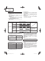
SPECIFICATIONS
POWER TOOL
Model P14DSL P18DSL
Cutting Width 82 mm
Max. Cutting Depth 2.0 mm
No-load speed 16000 min
-1
Rechargeable
battery
2LSRK BSL1430: Li-ion 14.4 V (3.0 Ah 8 cells)
BSL1830: Li-ion 18 V (3.0 Ah 10 cells)
2LJRK
BSL1450: Li-ion 14.4 V (5.0 Ah 8 cells) BSL1850: Li-ion 18 V (5.0 Ah 10 cells)
Weight
* 3.2 kg (With BSL1430) 3.3 kg (With BSL1830)
* Weight: According to EPTA-Procedure 01/2003
CHARGER
Model UC18YFSL
Charging voltage 14.4 V – 18 V
Weight 0.5 kg
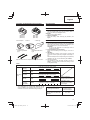
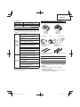
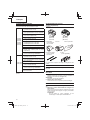
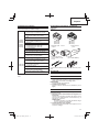
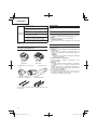
STANDARD ACCESSORIES
In addition to the main unit (1), the package contains the
accessories listed in the table below.
P14DSL
(2LSRK)
(2LJRK)
P18DSL
(2LSRK)
(2LJRK)
1 Box Wrench ............................................ 1
(for securing cutter blade)
2 Set Gauge ..............................................1
(for adjusting cutter height)
3 Guide ......................................................1
(with set screw)
4 Carbide Blade ........................................2
(Double edged Blade type)
5 Charger ..................................................1
6 Battery ....................................................2
[P14DSL] BSL1430 or BSL1450
[P18DSL] BSL1830 or BSL1850
7 Plastic case ............................................1
8 Battery cover ..........................................2
9 Spare carbide Blade set ......................... 1
(Not supplied in all areas)
0 Blade Sharpening Ass'y .........................1
(for Resharpenable Blade Type)
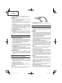
◯ Either install the battery in the power tool or store
by securely pressing into the battery cover until the
ventilation holes are concealed to prevent short-
circuits (See Fig. 5).
P14DSL (NN)
P18DSL (NN)
1 Box Wrench ............................................ 1
(for securing cutter blade)
2 Set Gauge ..............................................1
(for adjusting cutter height)
3 Guide ......................................................1
(with set screw)
4 Carbide Blade ........................................2
(Double edged Blade type)
5 Blade Sharpening Ass'y .........................1
(for Resharpenable Blade Type)
Without chager, battery, plastic case and
battery cover.
Standard accessories are subject to change without notice.

English
15
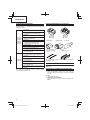
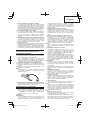
OPTIONAL ACCESSORIES (sold separately)
(BSL1430)
(BSL1440)
(BSL1450)
(BSL1830)
(BSL1840)
(BSL1850)
1. Battery
5. Carbide Blade
(Double edged Blade
type)
6. Blade
(Resharpenable blade
type)
2. Dust adapter 3. Elbow 4. Dust bag
Optional accessories are subject to change without notice.
APPLICATIONS
Planing various wooden planks and panels. (See Fig. 1-4)
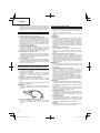
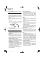
BATTERY REMOVAL/INSTALLATION
1. Battery removal
Hold the handle tightly and push the battery latch to
remove the battery (see Figs. 5 and 6).
CAUTION
Never short-circuit the battery.
2. Battery installation
Insert the battery while observing its polarities (see
Fig. 6).
CHARGING
Before using the power tool, charge the battery as follows.
1. Connect the charger's power cord to the receptacle.
When the power cord is connected, the charger’s pilot
lamp will blink in red. (At 1-second intervals)
CAUTION
Do not use the electrical cord if damaged. Have it
repaired immediately.
2. Insert the battery into the charger.
Firmly insert the battery into the charger, as shown in
Fig. 7.
3. Charging
When inserting a battery in the charger, charging will
commence and the pilot lamp will light continuously in
red.
When the battery becomes fully recharged, the pilot lamp
will blink in red. (At 1-second intervals) (See Table 1)
(1) Pilot lamp indication
The indications of the pilot lamp will be as shown in
Table 1, according to the condition of the charger or the
rechargeable battery.
Table 1
Indications of the pilot lamp
Pilot lamp
(red)
Before
charging
Blinks
Lights for 0.5 seconds. Does not light
for 0.5 seconds. (off for 0.5 seconds)
While
charging
Lights
Lights continuously
Charging
complete
Blinks
Lights for 0.5 seconds. Does not light
for 0.5 seconds. (off for 0.5 seconds)
Overheat
standby
Blinks
Lights for 1 second. Does not light
for 0.5 seconds. (off for 0.5 seconds)
Battery overheated.
Unable to charge.
(Charging will commence
when battery cools)
Charging
impossible
Flickers
Lights for 0.1 seconds. Does not light for
0.1 seconds. (off for 0.1 seconds)
Malfunction in the battery
or the charger
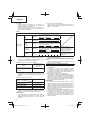
(2) Regarding the temperatures of the rechargeable battery
The temperatures for rechargeable batteries are as
shown in Table 2, and batteries that have become hot
should be cooled for a while before being recharged.
Table 2 Recharging ranges of batteries
Rechargeable batteries
Temperatures at
which the battery
can be recharged
BSL1430, BSL1440, BSL1450,
BSL1820, BSL1830, BSL1840,
BSL1850
0°C – 40°C

English
16
(3) Regarding recharging time
Depending on the combination of the charger and
batteries, the charging time will become as shown in
Table 3.
Table 3 Charging time (At 20°C)
Charger
Battery
UC18YFSL
BSL1820 Approx. 30 min.
BSL1430, BSL1830 Approx. 45 min.
BSL1440, BSL1840 Approx. 60 min.
BSL1450, BSL1850 Approx. 75 min.
NOTE
The charging time may vary according to temperature
and power source voltage.
CAUTION
When the battery charger has been continuously used,
the battery charger will be heated, thus constituting
the cause of the failures. Once the charging has been
completed, give 15 minutes rest until the next charging.
4. Disconnect the charger’s power cord from the
receptacle.
5. Hold the charger fi rmly and pull out the battery.
NOTE
Be sure to pull out the battery from the charger after use,
and then keep it.
How to make the batteries perform longer
(1) Recharge the batteries before they become completely
exhausted.
When you feel that the power of the tool becomes
weaker, stop using the tool and recharge its battery. If
you continue to use the tool and exhaust the electric
current, the battery may be damaged and its life will
become shorter.
(2) Avoid recharging at high temperatures.
A rechargeable battery will be hot immediately after use.
If such a battery is recharged immediately after use, its
internal chemical substance will deteriorate, and the
battery life will be shortened. Leave the battery and
recharge it after it has cooled for a while.
CAUTION
○ If the battery is charged while it is heated because it has
been left for a long time in a location subject to direct
sunlight or because the battery has just been used, the
pilot lamp of the charger lights for 1 second, does not
light for 0.5 seconds (off for 0.5 seconds). In such a case,
fi rst let the battery cool, then start charging.
○ When the pilot lamp fl ickers in red (at 0.2-seconds
intervals), check for and take out any foreign objects in
the charger’s battery connector. If there are no foreign
objects, it is probable that the battery or charger is
malfunctioning. Take it to your authorized Service
Center.
○ Since the built-in micro computer takes about 3
seconds to confi rm that the battery being charged with
UC18YFSL is taken out, wait for a minimum of 3 seconds
before reinserting it to continue charging. If the battery
is reinserted within 3 seconds, the battery may not be
properly charged.
○ If the pilot lamp does not blink in red (every second) even
though the charger cord is connected to the power, it
indicates that the protection circuit of the charger may be
activated.
Remove the cord from the power and then connect it
again after 30 seconds or so. If this does not cause the
pilot lamp to blink in red (every second), please take the
charger to the Hitachi Authorized Service Center.
PRIOR TO OPERATION
1. Setting up and checking the work environment
Check if the work environment is suitable by following the
precautions.
2. Power switch
Ensure that the power switch is in the OFF position. If the
battery is attached to the body while the power switch
is in the ON position, the power tool will start operating
immediately, which could cause a serious accident.
3. Prepare a stable wooden workbench suitable for
planning operation. As a poorly balanced workbench
creates a hazard, ensure it is securely positioned on fi rm,
level ground.
PLANING PROCEDURES
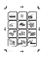
1. Operation of switch (Fig. 8)
(1) For safe operation of the machine, a “switch lock” is
provided on the side of a handle.
If the “switch trigger” is pulled in a state where “switch
lock” is pressed in the direction of the arrow mark, the
main switch can be turned ON.
(2) After the switch is turned ON, even when you release
your hand from the switch lock, the body continues
running and the light continues being turned ON as long
as you keep on pulling the switch trigger.
(3) If you release the switch trigger, you can turn OFF the
switch and the “switch lock” returns to the original
position automatically.
CAUTION
Do not fi x and secure the switch lock. Besides, keep
your fi nger off the switch trigger when the planer is
being carried around. Otherwise, the main body switch
can be inadvertently turned ON, resulting in unexpected
accidents.
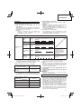
2. About remaining battery indicator
When pressing the remaining battery indicator switch,
the remaining battery indicator lamp lights and the
battery remaining power can be checked. (Fig. 9)
When releasing your fi nger from the remaining battery
indicator switch, the remaining battery indicator lamp
goes off . The Table 4 shows the state of remaining
battery indicator lamp and the battery remaining power.
Table 4
State of lamp Battery Remaining Power
The battery remaining power is enough.
The battery remaining power is a half.
The battery remaining power is nearly
empty.
Re-charge the battery soonest possible.
As the remaining battery indicator shows somewhat
diff erently depending on ambient temperature and battery
characteristics, read it as a reference.
NOTE
◯ Do not give a strong shock to the switch panel or break it.
It may lead to a trouble.
◯ To save the battery power consumption, the remaining
battery indicator lamp lights while pressing the remaining
battery indicator switch.

English
17
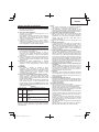
3. Adjusting the cutter depth
(1) Turn the knob in the direction indicated by the arrow in
Fig. 10 (clockwise), until the triangular mark is aligned
with the desired cutting depth on the scale. The scale unit
is graduated in millimeters.
(2) The cutting depth can be adjusted within a range of 0-2.0
mm.
4. Surface cutting
Rough cutting should be accomplished at large cutting
depths and at a suitable speed so that shavings are
smoothly ejected from the machine.
To ensure a smoothly fi nished surface, fi nish cutting
should be accomplished at small cutting depths and at
low feeding speed.
5. Beginning and ending the cutting operation
As shown in Fig. 11, place the front base of the planer on
the material and support the planer horizontally. Turn ON
the power switch, and slowly operate the planer toward
the leading edge of the material. Firmly depress the front
half of the planer at the fi rst stage of cutting, as shown in
Fig. 12, depress the rear half of the planer at the end of
the cutting operation. The planer must always be kept fl at
throughout the entire cutting operation.
6. Precaution after fi nishing the planing operation
When the planer is suspended with one hand after
fi nishing the planing operation, ensure that the cutting
blades (base) of the planer do not contact or come too
near your body. Failure to do so could result in serious
injury.
7. Stand
Lift the back of the planer to extend the foot from the
base. Having the stand extended when you put the
planer down prevents contact between the blade and the
material. (Fig. 13)
8. Regulating the guide (Fig. 14)
The planing position can be regulated by moving the
guide to the left or right after loosening its set screw. The
guide may be mounted on either the right or left side of
the tool.
Work Precautions
◯ About Continuous Operation
This tool is provided with a protective function to extend
battery life.
The battery may become overheated during continuous
operation or deep cutting operations, which may cause it
to automatically stop.
Especially with any of the batteries listed below, the tool
may stop operation before the battery starts to get hot to
prevent rapid failure from overheating.
If this happens, stop operation, remove the battery from
the tool and leave it in a well-ventilated location not
exposed to sunlight until it is suffi ciently cool.
The battery can be used again once it is cool.
(Applicable batteries: BSL1425, BSL1420, BSL1415,
BSL1825, BSL1820, BSL1815 and old batteries)
◯ Proper Battery Usage
When the tool is used with any of the batteries listed
below, it should be used for light work to extend battery
life.
Work example: Shallow depth fi nishing and chamfering
work
(Applicable batteries: BSL1425, BSL1420, BSL1415,
BSL1825, BSL1820, BSL1815 and old batteries)
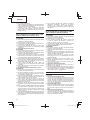
CARBIDE BLADE ASSEMBLY AND
DISASSEMBLY AND ADJUSTMENT OF CUTTER
BLADE HEIGHT (FOR DOUBLE EDGED BLADE
TYPE)
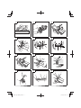
1. Carbide blade disassembly
CAUTION
○ To prevent accidents, ensure that the power tool is
switched off and pull out the battery.
○ Be careful not to injure your hands.
(1) As shown in Fig. 15, loosen the blade holder with the
attached box wrench.
(2) As shown in Fig. 16, remove the carbide blade by sliding
it with the attached box wrench.
2. Carbide blade assembly
CAUTION
○ To prevent accidents, ensure that the power tool is
switched off and pull out the battery.
○ Prior to assembly, thoroughly wipe off all swarf
accumulated on the carbide blade.
(1) As shown in Fig. 17, lift set plate (B) and insert the new
carbide blade between cutter block and set plate (B).
(2) As shown in Fig. 18, mount the new carbide blade by
sliding it on the set plate (B) so that the blade tip projects
by 1mm from the end of the cutter block.
(3) As shown in Fig. 19, fi x the bolts at the blade holder after
blade replacement has been completed.
(4) Turn the cutter block over, and set the other side in the
same manner.
3. Adjustment of carbide blade height
CAUTION
○ To prevent accidents, ensure that the power tool is
switched off and pull out the battery.
○ If the carbide blade’s heights are inaccurate after
above procedures have been completed, carry out the
procedures described below.
(1) As shown in Fig. 20, use the box wrench to loosen the
three bolts used to retain the carbide blade, and remove
the blade holder.
(2) As shown in Fig. 21, after removing the carbide blade,
slide set plate (B) in the direction indicated by the arrow
to disassemble set plate (B).
(3) Loosen the 2 screws holding on the carbide blade and
set plate (A), set plate (B).
(4) As shown in Fig. 22, 23, press the turned surface of set
plate (A) to the wall surface b while adjusting the carbide
blade edge to the wall surface a of the set gauge. Then,
tighten them with the 2 screws.
(5) As shown in Fig. 24, 25, insert a turned portion of set
plate (A) attached to set plate (B) into a groove on the fl at
portion of the cutter block.
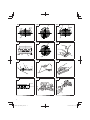
(6) As shown in Fig. 26, place the blade holder on the
completed assembly and fasten it with the three bolts.
Ensure that the bolts are securely tightened. Follow the
same procedures for the opposite side carbide blade.
BLADE ASSEMBLY AND DISASSEMBLY
AND ADJUSTMENT OF BLADE HEIGHT (FOR
RESHARPENABLE BLADE TYPE)
1. Blade disassembly
CAUTION
○ To prevent accidents, ensure that the power tool is
switched off and pull out the battery.
○ Be careful not to injure your hands.
(1) As shown in Fig. 20, use the accessory box wrench
to loosen the three bolts used to retain the blade, and
remove the blade holder.

English
18
(2) As shown in Fig. 21, slide the blade in the direction
indicated by the arrow to disassemble the blade.
2. Blade assembly
CAUTION
○ To prevent accidents, ensure that the power tool is
switched off and pull out the battery.
○ Prior to assembly, thoroughly wipe off all swarf
accumulated on the blade.
(1) Insert a turned portion of set plate (A) attached to the
blade into a groove on the fl at portion of the cutter block.
(Fig. 24, 27)
Set the blade so that both sides of the blade protrude
from the width of the cutter block by about 1 mm (Fig. 28)
(2) Place the blade holder on the completed assembly,
as shown in Fig. 29, and fasten it with the three bolts.
Ensure that the bolts are securely tightened.
(3) Turn the cutter block over, and set the opposite side in
the same manner.
3. Adjustment of blade height
(1) Loosen the 2 screws holding on the blade and set plate
(A). (Fig. 30)
(2) Press the turned surface of set plate (A) to the wall surface
b while adjusting the blade edge to the wall surface a of
the set gauge. Then, tighten them with the 2 screws. (Fig.
22, 31)
SHARPENING THE RESHARPENABLE BLADES
Use of the accessory Blade Sharpening Ass'y is
recommended for convenience.
1. Use of Blade Sharpening Ass'y
As shown in Fig. 32, two blades can be mounted on the
blade sharpening ass'y to ensure that the blade tips are
ground at uniform angles. During grinding, adjust the
position of the blades so that their edges simultaneously
contact the dressing stone as shown in Fig. 33.
2. Blade sharpening intervals
Blade sharpening intervals depend on the type of wood
being cut and the cutting depth. However, sharpening
should generally be eff ected after each 500 meters of
cutting operation.
3. Grinding allowance of the cutter blades
As illustrated in Fig. 34, a grinding allowance of 3.5mm
is provided for on the cutter blade. That is, the cutter
blade can be repeatedly sharpened until its total height
is reduced to 24.5 mm.
4. Grinding Stone
When a water grinding stone is available, use it after
dipping it suffi ciently in water since such a grinding
stone may be worn during grinding procedures, fl atten
the upper surface of the grinding stone as frequently as
possible.
ATTACHING AND DETACHING THE DUST
ADAPTER (OPTIONAL ACCESSORY)
CAUTION
○ To prevent accidents, ensure that the power tool is
switched off and pull out the battery.
○ Follow the procedure below to mount the dust adapter
securely. Failure to do so may result in the adapter
coming off , causing injury.
1. Attaching the dust adapter
(1) Remove the screw D4 × 16 in the chip cover and remove
the chip cover as shown in Fig. 35.
(2) Mount the dust adapter and secure with the screw D4 ×
16. (Fig. 36)
NOTE
Take care not to break the catch when attaching or
detaching the dust adapter and chip cover.
2. Removing the dust adapter
To remove the dust adapter, follow the procedure above
in reverse order.
MAINTENANCE AND INSPECTION
1. Inspecting the blades
Continued use of dull or damaged blades will result in
reduced cutting effi ciency and may cause overloading
of the motor. Sharpen or replace the blades as often as
necessary.
2. Handling
CAUTION
The front base, rear base, and cutting depth control
knob are precisely machined to obtain specifi cally high
precision. If these parts are roughly handled or subjected
to heavy mechanical impact, it may cause deteriorated
precision and reduced cutting performance. These parts
must be handled with particular care.
3. Inspecting the mounting screws
Regularly inspect all mounting screws and ensure that
they are properly tightened. Should any of the screws be
loose, retighten them immediately. Failure to do so could
result in serious hazard
4. Inspecting the carbon brushes (Fig. 37)
The motor employs carbon brushes which are
consumable parts. Since and excessively worn carbon
brush can result in motor trouble, replace the carbon
brush with new ones when it becomes worn to or near
the “wear limit”. In addition, always keep carbon brushes
clean and ensure that they slide freely whthin the brush
holders.
NOTE
When replacing the carbon brush with a new one, be sure
to use the Hitachi Carbon Brush Code No. 999017.
5. Replacing carbon brushes
After removing the chip cover, take out the carbon brush
by fi rst removing the brush cap and then hooking the
protrusion of the carbon brush with a slotted head screw
driver, etc., as shown in Fig. 38.
When installing the carbon brush, choose the direction
so that the nail of the carbon brush agrees with the
contact portion outside the brush tube. Then push it in
with a fi nger as illustrated in Fig. 39. Lastly, install the
brush cap.
CAUTION
Be absolutely sure to insert the nail of the carbon brush
into the contact portion outside the brush tube.
(You can insert whichever one of the two nails provided.)
Caution must be exercised since any error in this
operation can result in the deformed nail of the carbon
brush and may cause motor trouble at an early stage.
6. Maintenance of the motor
The motor unit winding is the very “heart” of the power
tool.
Exercise due care to ensure the winding does not
become damaged and/or wet with oil or water.
7. Cleaning on the outside
When the planer is stained, wipe with a soft dry cloth or
a cloth moistened with soapy water. Do not use chloric
solvents, gasoline or paint thinner, for they melt plastics.

English
19
8. Storage
Store the planer in a place in which the temperature is
less than 40°C and out of reach of children.
NOTE
Make sure that the battery is fully charged when stored
for a long period (3 months or more). The battery with
smaller capacity may not be able to be charged when
used, if stored for a long period.
NOTE
Storing lithium-ion batteries
Make sure the lithium-ion batteries have been fully
charged before storing them.
Prolonged storage of batteries with a low charge may
result in performance deterioration, signifi cantly reducing
battery usage time or rendering the batteries incapable of
holding a charge.
However, signifi cantly reduced battery usage time may
be recovered by repeatedly charging and using the
batteries two to fi ve times.
If the battery usage time is extremely short despite
repeated charging and use, consider the batteries dead
and purchase new batteries.
9. Service parts list
CAUTION
Repair, modifi cation and inspection of Hitachi Power
Tools must be carried out by a Hitachi Authorized Service
Center.
This Parts List will be helpful if presented with the tool to
the Hitachi Authorized Service Center when requesting
repair or other maintenance.
In the operation and maintenance of power tools, the
safety regulations and standards prescribed in each
country must be observed.
MODIFICATIONS
Hitachi Power Tools are constantly being improved
and modifi ed to incorporate the latest technological
advancements.
Accordingly, some parts may be changed without prior
notice.
Important notice on the batteries for the Hitachi
cordless power tools
Please always use one of our designated genuine
batteries. We cannot guarantee the safety and
performance of our cordless power tool when used with
batteries other than these designated by us, or when
the battery is disassembled and modifi ed (such as
disassembly and replacement of cells or other internal
parts).
GUARANTEE
We guarantee Hitachi Power Tools in accordance with
statutory/country specifi c regulation. This guarantee does
not cover defects or damage due to misuse, abuse, or normal
wear and tear. In case of complaint, please send the Power
Tool, undismantled, with the GUARANTEE CERTIFICATE
found at the end of this Handling instruction, to a Hitachi
Authorized Service Center.
NOTE
Due to HITACHI’s continuing program of research and
development, the specifi cations herein are subject to change
without prior notice.
Information concerning airborne noise and vibration
The measured values were determined according to
EN60745 and declared in accordance with ISO 4871.
Measured A-weighted sound power level:
94 dB (A) (P14DSL)
95 dB (A) (P18DSL)
Measured A-weighted sound pressure level:
83 dB (A) (P14DSL)
84 dB (A) (P18DSL)
Uncertainty KpA: 3 dB (A).
Wear hearing protection.
Vibration total values (triax vector sum) determined according
to EN60745.
Planing softwood:
Vibration emission value
ah = 2.6 m/s
2
(P14DSL)
3.0 m/s
2
(P18DSL)
Uncertainty K = 1.5 m/s
2
The declared vibration total value has been measured in
accordance with a standard test method and may be used
for comparing one tool with another.
It may also be used in a preliminary assessment of
exposure.
WARNING
○ The vibration emission during actual use of the power
tool can diff er from the declared total value depending on
the ways in which the tool is used.
○ Identify safety measures to protect the operator that
are based on an estimation of exposure in the actual
conditions of use (taking account of all parts of the
operating cycle such as the times when the tool is
switched off and when it is running idle in addition to the
trigger time).

Deutsch
20
ALLGEMEINE SICHERHEITSHINWEISE FÜR
ELEKTROGERÄTE
WARNUNG
Lesen Sie sämtliche Sicherheitshinweise und
Anweisungen durch.
Wenn die Warnungen und Anweisungen nicht befolgt
werden, kann es zu Stromschlag, Brand und/oder ernsthaften
Verletzungen kommen.
Bitte bewahren Sie alle Warnhinweise und Anweisungen
zum späteren Nachschlagen auf.
Der Begriff „Elektrowerkzeug“ bezieht sich in den
Warnhinweisen auf Elektrowerkzeuge mit Netz-
(schnurgebunden) oder Akkubetrieb (schnurlos).
1) Sicherheit im Arbeitsbereich
a) Sorgen Sie für einen sauberen und gut
ausgeleuchteten Arbeitsbereich.
Zugestellte oder dunkle Bereiche ziehen Unfälle
förmlich an.
b) Verwenden Sie Elektrowerkzeuge niemals an
Orten, an denen Explosionsgefahr besteht – zum
Beispiel in der Nähe von leicht entfl ammbaren
Flüssigkeiten, Gasen oder Stäuben.
Bei der Arbeit mit Elektrowerkzeugen kann es zu
Funkenbildung kommen, wodurch sich Stäube oder
Dämpfe entzünden können.
c) Sorgen Sie bei der Arbeit mit Elektrowerkzeugen
dafür, dass sich keine Zuschauer (insbesondere
Kinder) in der Nähe befi nden.
Wenn Sie abgelenkt werden, können Sie die Kontrolle
über das Werkzeug verlieren.
2) Elektrische Sicherheit
a) Elektrowerkzeuge müssen mit passender
Stromversorgung betrieben werden.
Nehmen Sie niemals irgendwelche Änderungen
am Anschlussstecker vor.
Verwenden Sie bei Elektrowerkzeugen
mit Schutzkontakt (geerdet) niemals
Adapterstecker.
Stecker im Originalzustand und passende
Steckdosen reduzieren das Stromschlagrisiko.
b) Vermeiden Sie Körperkontakt mit geerdeten
Gegenständen wie Rohrleitungen, Heizungen,
Herden oder Kühlschränken.
Bei Körperkontakt mit geerdeten Gegenständen
besteht ein erhöhtes Stromschlagrisiko.
c) Setzen Sie Elektrowerkzeuge niemals Regen
oder sonstiger Feuchtigkeit aus.
Wenn Flüssigkeiten in ein Elektrowerkzeug
eindringen, erhöht sich das Stromschlagrisiko.
d) Verwenden Sie das Anschlusskabel nicht
missbräuchlich. Tragen Sie das Elektrowerkzeug
niemals an der Anschlussschnur, ziehen
Sie es nicht damit heran und ziehen Sie den
Stecker nicht an der Anschlussschnur aus der
Steckdose.
Halten Sie die Anschlussschnur von Hitzequellen,
Öl, scharfen Kanten und beweglichen Teilen
fern.
Beschädigte oder verdrehte Anschlussschnüre
erhöhen das Stromschlagrisiko.
e) Wenn Sie ein Elektrowerkzeug im Freien
benutzen, verwenden Sie ein für den
Außeneinsatz geeignetes Verlängerungskabel.
Ein für den Außeneinsatz geeignetes Kabel
vermindert das Stromschlagrisiko.
f) Falls sich der Betrieb des Elektrowerkzeuges
in feuchter Umgebung nicht vermeiden lässt,
verwenden Sie eine Stromversorgung mit
Fehlerstromschutzeinrichtung (Residual
Current Device, RCD).
Durch den Einsatz einer Fehlerstromschutzeinrichtung
wird das Risiko eines elektrischen Schlages
reduziert.
3) Persönliche Sicherheit
a) Bleiben Sie wachsam, achten Sie auf das, was
Sie tun, und setzen Sie Ihren Verstand ein, wenn
Sie mit Elektrowerkzeugen arbeiten.
Benutzen Sie keine Elektrowerkzeuge, wenn
Sie müde sind oder unter Einfl uss von Drogen,
Alkohol oder Medikamenten stehen.
Bei der Arbeit mit Elektrowerkzeugen können bereits
kurze Phasen der Unaufmerksamkeit zu schweren
Verletzungen führen.
b) Benutzen Sie eine persönliche Schutzausrüstung.
Tragen Sie immer einen Augenschutz.
Schutzausrüstung wie Staubmaske, rutschsichere
Sicherheitsschuhe, Schutzhelm und Gehörschutz
senken das Verletzungsrisiko bei angemessenem
Einsatz.
c) Vermeiden Sie unbeabsichtigtes Einschalten.
Achten Sie darauf, dass sich der Schalter
in der Aus- (Off -) Position befi ndet, ehe Sie
das Gerät mit der Stromversorgung und/
oder Batteriestromversorgung verbinden, es
aufheben oder herumtragen.
Das Herumtragen von Elektrowerkzeugen mit
dem Finger am Schalter oder das Herstellen der
Stromversorgung bei betätigtem Schalter zieht
Unfälle regelrecht an.
d) Entfernen Sie sämtliche Einstellwerkzeuge
(Einstellschlüssel), ehe Sie das Elektrowerkzeug
einschalten.
Ein an einem beweglichen Teil des Elektrowerkzeugs
angebrachter Schlüssel kann zu Verletzungen
führen.
e) Sorgen Sie für einen festen Stand. Achten Sie
jederzeit darauf, sicher zu stehen und das
Gleichgewicht zu bewahren.
Dadurch haben Sie das Elektrowerkzeug in
unerwarteten Situationen besser im Griff .
f) Kleiden Sie sich richtig. Tragen Sie keine lose
Kleidung oder Schmuck. Halten Sie Haar,
Kleidung und Handschuhe von beweglichen
Teilen fern.
Lose Kleidung, Schmuck oder langes Haar kann von
beweglichen Teilen erfasst werden.
g) Wenn Anschlüsse für Staubabsaug- und
-sammelvorrichtungen vorhanden sind, sorgen
Sie dafür, dass diese richtig angeschlossen und
eingesetzt werden.
Durch Entfernen des Staubes können staubbezogene
Gefahren vermindert werden.
4) Einsatz und Pfl ege von Elektrowerkzeugen
a) Überanspruchen Sie Elektrowerkzeuge nicht.
Benutzen Sie das richtige Elektrowerkzeug für
Ihren Einsatzzweck.
Das richtige Elektrowerkzeug erledigt seine Arbeit bei
bestimmungsgemäßem Einsatz besser und sicherer.
b) Benutzen Sie das Elektrowerkzeug nicht, wenn es
sich nicht am Schalter ein- und ausschalten lässt.
Jedes Elektrowerkzeug, das nicht mit dem Schalter
betätigt werden kann, stellt eine Gefahr dar und muss
repariert werden.
(Übersetzung der ursprünglichen Anleitung)
La pagina si sta caricando...
La pagina si sta caricando...
La pagina si sta caricando...
La pagina si sta caricando...
La pagina si sta caricando...
La pagina si sta caricando...
La pagina si sta caricando...
La pagina si sta caricando...
La pagina si sta caricando...
La pagina si sta caricando...
La pagina si sta caricando...
La pagina si sta caricando...
La pagina si sta caricando...
La pagina si sta caricando...
La pagina si sta caricando...
La pagina si sta caricando...
La pagina si sta caricando...
La pagina si sta caricando...
La pagina si sta caricando...
La pagina si sta caricando...
La pagina si sta caricando...
La pagina si sta caricando...
La pagina si sta caricando...
La pagina si sta caricando...
La pagina si sta caricando...
La pagina si sta caricando...
La pagina si sta caricando...
La pagina si sta caricando...
La pagina si sta caricando...
La pagina si sta caricando...
La pagina si sta caricando...
La pagina si sta caricando...
La pagina si sta caricando...
La pagina si sta caricando...
La pagina si sta caricando...
La pagina si sta caricando...
La pagina si sta caricando...
La pagina si sta caricando...
La pagina si sta caricando...
La pagina si sta caricando...
La pagina si sta caricando...
La pagina si sta caricando...
La pagina si sta caricando...
La pagina si sta caricando...
La pagina si sta caricando...
La pagina si sta caricando...
La pagina si sta caricando...
La pagina si sta caricando...
La pagina si sta caricando...
La pagina si sta caricando...
La pagina si sta caricando...
La pagina si sta caricando...
La pagina si sta caricando...
La pagina si sta caricando...
La pagina si sta caricando...
La pagina si sta caricando...
La pagina si sta caricando...
La pagina si sta caricando...
La pagina si sta caricando...
La pagina si sta caricando...
-
 1
1
-
 2
2
-
 3
3
-
 4
4
-
 5
5
-
 6
6
-
 7
7
-
 8
8
-
 9
9
-
 10
10
-
 11
11
-
 12
12
-
 13
13
-
 14
14
-
 15
15
-
 16
16
-
 17
17
-
 18
18
-
 19
19
-
 20
20
-
 21
21
-
 22
22
-
 23
23
-
 24
24
-
 25
25
-
 26
26
-
 27
27
-
 28
28
-
 29
29
-
 30
30
-
 31
31
-
 32
32
-
 33
33
-
 34
34
-
 35
35
-
 36
36
-
 37
37
-
 38
38
-
 39
39
-
 40
40
-
 41
41
-
 42
42
-
 43
43
-
 44
44
-
 45
45
-
 46
46
-
 47
47
-
 48
48
-
 49
49
-
 50
50
-
 51
51
-
 52
52
-
 53
53
-
 54
54
-
 55
55
-
 56
56
-
 57
57
-
 58
58
-
 59
59
-
 60
60
-
 61
61
-
 62
62
-
 63
63
-
 64
64
-
 65
65
-
 66
66
-
 67
67
-
 68
68
-
 69
69
-
 70
70
-
 71
71
-
 72
72
-
 73
73
-
 74
74
-
 75
75
-
 76
76
-
 77
77
-
 78
78
-
 79
79
-
 80
80


Hikoki P14DSL Manuale utente
- Categoria
- Utensili elettrici
- Tipo
- Manuale utente
- Questo manuale è adatto anche per
in altre lingue
- English: Hikoki P14DSL User manual
- français: Hikoki P14DSL Manuel utilisateur
- español: Hikoki P14DSL Manual de usuario
- Deutsch: Hikoki P14DSL Benutzerhandbuch
- Nederlands: Hikoki P14DSL Handleiding
- português: Hikoki P14DSL Manual do usuário
Documenti correlati
-
Hikoki P14DSL Manuale utente
-
Hikoki DS18DE Manuale utente
-
-
-
-
-
-
-
-
Hitachi DV18DSL Manuale utente
Altri documenti
-
-
Hitachi DV 18DSFL Manuale del proprietario
-
Hitachi CJ 14DSL Istruzioni per l'uso
-
Hitachi DS 14 DJ L Manuale del proprietario
-
-
 Virutex ABB400 Manuale del proprietario
-
Infocus P 20SE Manuale utente
-
-
-
