
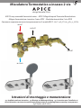
Miscelatore Termostatico a incasso 2 vie
APICE 2-ways concealed thermostatic mixer - APICE 2-Wege Unterputz Thermostat Brausebatterie
Mitigeur thermostatique à encastrer 2 voies APICE - Mezclador termostático 2 vías APICE
Смеситель термостатический встраиваемый на 2 выхода APICE -
Istruzioni di montaggio e manutenzione
Installation and care instructions Montage-und Wartungsanleitung Instructions pour l’installation et
conseils d’entretien Instrucciones de montaje y de mantenimiento Инструкция по монтажу и эксплуатации
OUTLET
IN COLD
IN HOT
OUTLET
design Marcello Ziliani
AR

1
2
15
20
3
2
2.5
4
5
9
10 11
6
7
8
12
13 17 14
17 16
16
18
19
21
22
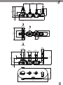
2

G 1/2"
IN
COLD WATER
G 1/2"
IN
HOT WATER
G 1/2"
OUT
OUT
139
76
66
34
42
M4
71.5 71.5
278
101
42
19.5
120
75
75
82
120
338
157
145
Ø29
Ø27.5
Ø27.5
Ø45
5
19.5 40.5 - 54.5
3

4
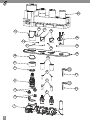
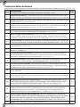
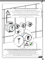
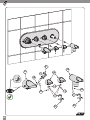
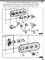
Contenuto della confezione
Package content - Inhalt der Verpackung - Contenu de l’emballage - Contenido del embalaje - Содержимое упаковки -
Item Descrizione
Description - Beschreibung - Description - Descripción - Oписание - Q.Ty
1
Corpo miscelatore ad incasso - Concealed body of the mixer - Unterputz Einbaukörper der Armatur Corps à
encastrer du mitigeur - Cuerpo empotrado del mezclador - ВстраиВаемый корпус смесителя -
1
2Valvolina non ritorno - Check valve - Rückschlagventil - Petit clapet anti-retour - Válvula de retención
- НеВозВратНый клапа - 2
3
Tappi per chiusura valvolina non ritorno - Taps for closing of the check valve - Schließen Stopfen
des Rückschlagventils - Bouchons de fermeture du clapet anti-retour - Tapas de bloqueo para válvula
antirretorno - заглушки НеВозВратНого клапаНа -
2
4Cartuccia termostatica - Thermostatic cartridge - Thermomischkartusche - Cartouche thermostati-
que - Cartucho termostático - Термостатический картридж - 1
5
Ghiera serraggio cartuccia termostatica - Thermostatic cartridge tightening ring nut - Thermomischkar-
tuschen-Druckhülse - Bague de serrage de cartouche thermostatique - Cápsula de sujeción de cartucho
termostático - Зажимное кольцо термостатического картриджа -
1
6
Cartuccia rubinetto - On/o/regulation valve cartridge - On/o/Regulierung Hahnkartusche - Cartouche du
robinet marche/arrêt/réglage - Cartucho mezclador de cierre y reglar - Картридж вентиля -
2
7Astina cartuccia - Cartridge shaft - Kartuschenstift - Broche de la cartouche - Manguito del cartucho
- Щуп картриджа - 2
8Vite M4x25 mm - Screw M4x25 mm - Schraub M4x25 mm - Vis M4x25 mm - Tornillo M4x25 mm - ВиНт
M4x25 мм - 2
9
Cannotto estetico per termostatico - Esthetical bush for thermostatic unit - Ästhetische Buchse
der Thermostat Einheit - Douille esthétique pour le mitigeur thermostatique - Casquillo estético para
termostático - Декоративная втулка термостата -
1
10 Camma con fermo 38°C - Hot limit safety stop at 38°C - Nocken mit Feststellmöglichkeit 38°C - Came
avec arrêt à 38°C - Leva con retén 38°C -
Эксцентрик фиксации 38°C -
1
11
Cannotto estetico per rubinetto - Esthetical bush for stop valve - Ästhetische Buchse des On/off/
Regulierung Hahns - Douille esthétique pour le robinet marche/arrêt/réglage - Casquillo estético para
mezclador de cierre y reglar - ДекоратиВНая Втулка ВеНтиля -
2
12 Piastra di copertura - Cover plate - Abdeckplatte - Plaque de protection - Placa de cubiertas - лицеВая
паНель - 1
13
Manopola di regolazione temperatura - Temperature control knob - Temperaturwählgriff - Poi-
gnée de réglage température - Perilla de regulación temperatura - Ручка регулировки температуры
-
1
14
Manopola apertura-chiusura e regolazione usso - On-o and ow regulation handle - On-o
und Durchussregulierung Gri - Poignée marche/arrêt/réglage - Pomo mezclador de cierre y reglar
- Ручка открытия-закрытия и регулировки потока -
2
15
Grano ssaggio manopola termostatica M5x6 mm - M5x6mm threaded pin for thermostatic
handle xing - M5x6mm Gewindestift zur Befestigung des Thermostat Gris - Tige letée M5x6mm
pour xation de la poignée thermostatique - Tornillo de jación pomo termostático M5x6 mm -
Установочный винт ручки термостата M5x6 мм -
1
16
Grano ssaggio manopola rubinetto M4x3 mm - M4x3mm threaded pin for on/off/regulation
valve handle fixing - M4x3mm Gewindestift zur Befestigung des On/off/Regulierung Griffs - Tige filetée
M4x3mm pour fixation de la poignée du robinet marche/arrêt/réglage - Tornillo de fijación pomo
mezclador M4x3 mm - устаНоВочНый ВиНт ручки ВеНтиля M4x3 мм -
2
17 Tappino - Cap - Griffstopfen - Cache-vis - Tapón - Вкладка - 3
M4x25
38
M5x6
M4x3

5
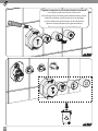
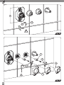
Item Descrizione
Description - Beschreibung - Description - Descripción - Oписание - Q.Ty
18
Supporto/presa acqua - Shower bracket/water inlet elbow - Brausehalter/Wandanschlussbogen -
Support douche/sortie murale - Soporte mango ducha/entrada agua - Держатель/ВоДорозетка
-
1
19
Grano ssaggio supporto/presa acqua M4x6 mm - M4x6mm threaded pin for shower bracket/water
inlet elbow fixing - M4x6mm Gewindestift zur Befestigung des Brausehalters/Wandanschlussbogens - Tige
filetée M4x6mm pour fixation du support douche/sortie murale - Tornillo de fijación soporte/entrada de
agua M4x6 mm - устаНоВочНый ВиНт Держателя/ ВоДорозетки M4x6 мм
-
1
20 Copertura in polistirolo - Polystyrene cover - Deckung aus Polystyrol - Couverture en polystyrène
- Cobertura en poliestireno - крышка из полистирола - 1
21-22 Chiave a brugola - Hex key - Sechskantschlüssel - Clé Allen - Llave Allen - Ключ - 1
M4x6
LEGGERE ATTENTAMENTE IL PRESENTE LIBRETTO DI INSTALLAZIONE E MANUTENZIONE.
READ THIS INSTALLATION AND CARE MANUAL CAREFULLY.
DIE VORLIEGENDE MONTAGE- UND WARTUNGSANLEITUNG AUFMERKSAM DURCHLESEN.
LIRE ATTENTIVEMENT CETTE NOTICE D’INSTALLATION ET D'ENTRETIEN.
LEA ATENTAMENTE ESTE MANUAL DE INSTALACIÓN Y MANTENIMIENTO.READ THIS
ВНИМАТЕЛЬНО ПРОЧИТАТЬ ИНСТРУКЦИЮ ПРЕЖДЕ, ЧЕМ ПРИСТУПАТЬ К УСТАНОВКЕ
INDOSSARE I DISPOSITIVI DI PROTEZIONE INDIVIDUALI.
PUT ON INDIVIDUAL PROTECTION DEVICES.
INDIVIDUELLE SCHUTZGERÄTE ÜBERZIEHEN.
METTRE DES DISPOSITIFS DE PROTECTION INDIVIDUELS.
PONER DISPOSITIVOS DE PROTECCIÓN INDIVIDUAL.
ИСПОЛЬЗОВАТЬ ИНДИВИДУАЛЬНЫЕ СРЕДСТВА ЗАЩИТЫ.

6
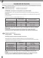
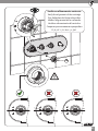
CARATTERISTICHE TECNICHE:
Indice alimentazione calda: identicata da tappo colore Rosso
Indice alimentazione fredda: identicata da tappo colore Blu
ATTENZIONE : non invertire il collegamento acqua calda e fredda.
Pulsante di blocco a 38°C per evitare manovre errate verso la richiesta di acqua calda non
desiderata
Dispositivo di sicurezza per l’elemento termosensibile per surriscaldamento dell’acqua calda
di alimentazione
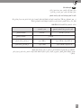
CONDIZIONI DI IMPIEGO SECONDO NORMA UNI EN 1111
Limiti di impiego Limiti raccomandati per un
corretto funzionamento
Pressione dinamica ≥ 0.5 bar ≥ 1 bar ÷ ≤ 5 bar
Pressione statica ≤ 10 bar
Temperatura acqua calda ≤ 90° C ≥ 55° C ÷ ≤ 65°C
Temperatura acqua fredda ≤ 25° C ≥ 5° C ÷ ≤ 20°C
I
NOTA: in caso di pressioni superiori a 5 bar si raccomanda di installare un riduttore
di pressione.
Per garantire il funzionamento ottimale del dispositivo è importante che le
pressioni di servizio (acqua calda e acqua fredda) siano il più possibile bilanciate.
TECHNICAL CHARACTERISTICS:
Hot water indicator: Identied by red cap
Cold water indicator: Identied by blue cap
CAUTION: do not invert the hot/cold water connections.
Lock button at 38°C to prevent accidental adjustment to very hot temperatures.
Safety device for the thermosensitive element to prevent the overheating of hot water inow.
CONDITIONS OF USE ACCORDING TO UNI EN 1111
Limits of use Recommended limits for a proper
functioning
Dynamic pressure ≥ 0.5 bar ≥ 1 bar ÷ ≤ 5 bar
Static pressure ≤ 10 bar
Warm water temperature ≤ 90° C ≥ 55° C ÷ ≤ 65°C
Cold water temperature ≤ 25° C ≥ 5° C ÷ ≤ 20°C
NOTE: In case of pressures above 5 bar it is recommended to install a pressure
reducer.
In order to assure the optimal functioning of the device , it is important that the
service pressures (cold and warm water) are as balanced as possible.
Caratteristiche Tecniche
Technical features - Caractéristiques techniques - Technische Eigenschaften -Características técnicas - Технические характеристики -

7
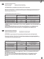
TECHNISCHE EIGENSCHAFTEN:
Warmwasseranzeige: Mit rotem Verschluss bezeichnet
Kaltwasseranzeige: Mit blauem Verschluss bezeichnet
ACHTUNG: Warm- und Kaltwasseranschluss nicht austauschen.
Blockierungsknopf bei 38°C, um falsche Handhabung zur Anforderung von nicht erwünschtem
Warmwasser zu verhindern. Sicherheitsvorrichtung für das wärmeempndliche Element zur
Überhitzung des Warmwassers.
NUTZUNGSBEDINGUNGEN GEMÄSS UNI EN 1111
Nutzungsbeschränkungen
Empfohlene Grenzen für ein
ordnungsgemäßes Funktionieren
Dynamischer Druck ≥ 0.5 bar ≥ 1 bar ÷ ≤ 5 bar
Statischer Druck ≤ 10 bar
Warmwasser Temperatur ≤ 90° C ≥ 55° C ÷ ≤ 65°C
Kaltwasser Temperatur ≤ 25° C ≥ 5° C ÷ ≤ 20°C
HINWEIS: Bei Wasser Drück mehr als 5 bar, wird es empfohlen, einen Druckminderer zu
installieren.
Um das optimale Funktionieren des Geräts zu gewährleisten, ist es wichtig, dass die
Betriebsdrücke (kaltes und warmes Wasser) so ausgeglichen wie möglich sind.
D
CARACTERISTIQUES TECHNIQUES:
Indicateur alimentation eau chaude : Identiée par un bouchon rouge
Indicateur alimentation eau froide : Identiée par un bouchon bleue
ATTENTION : ne pas intervertir le raccordement de l’eau chaude et de l’eau froide.
Bouton de verrouillage à 38°C pour éviter toute fausse manœuvre vers une demande d’eau
chaude non souhaitée. Dispositif de sécurité de l’élément thermosensible pour empêcher toute
surchaue de l’eau chaude d’alimentation.
CONDITIONS D'UTILISATION SELON UNI EN 1111
F
Limites d'utilisation Limites recommandées pour un
bon fonctionnement
Pression dynamique ≥ 0.5 bar ≥ 1 bar ÷ ≤ 5 bar
Pression statique ≤ 10 bar
Temperature eau chaude ≤ 90° C ≥ 55° C ÷ ≤ 65°C
Temperature eau froide ≤ 25° C ≥ 5° C ÷ ≤ 20°C
REMARQUE: En cas de pressions supérieures à 5 bar, il est recommandé d'installer
un réducteur de pression.
An d'assurer le fonctionnement optimal de l'appareil, il est important que les
pressions de service (eau froide et eau chaude) soient aussi équilibrées que
possible.

8
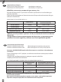
CARACTERÍSTICAS TÉCNICAS:
Indicación para la salida de agua caliente: identicada por un tapón rojo
Indicación para la salida de agua fría: identicada por un tapón azúl
ATENCIÓN: no invierta las entradas del agua caliente y fría.
Pulsador de bloqueo en 38°C para evitar maniobras equivocadas en la solicitud de agua
caliente no deseada.
Dispositivo de seguridad para el elemento termosensible por sobrecalentamiento del agua
caliente de alimentación.
CONDICIONES DE USO SEGÚN UNI EN 1111
E
Límites de uso Límites recomendados para un
buen funcionamiento
Presión dinámica ≥ 0.5 bar ≥ 1 bar ÷ ≤ 5 bar
Presión estática ≤ 10 bar
Temperatura agua caliente ≤ 90° C ≥ 55° C ÷ ≤ 65°C
Temperatura agua fria ≤ 25° C ≥ 5° C ÷ ≤ 20°C
NOTA: En caso de presiones superiores a 5 bar, se recomienda instalar un reductor
de presión.
Para garantizar el funcionamiento óptimo del dispositivo, es importante que las
presiones de servicio (agua fría y caliente) sean lo más equilibradas posible.
ТЕХНИЧЕСКИЕ ХАРАКТЕРИСТИКИ:
Указатель подведения горячей воды: Идентифицируется по красному цвету крышки
Указатель подведения холодной воды: Идентифицируется по синему цвету крышки
Внимание: НЕ ПЕРЕПУТАЙТЕ трубы подведения горячего и холодного водоснабжения к
смесителю
Кнопка блокатор на 38°C градусов, во избежание ошибочных манипуляций подачи
горячей воды.
Устройство, предохраняющее от перегрева горячей водой для
термочувствительного элемента.
ЭКСПЛУАТАЦИОННЫЕ УСЛОВИЯ СОГЛАСНО НОРМАТИВОВ UNI EN 1111
RUS
Ограничительные
пределы
Рекомендуемые пределы для
корректного использования
Динамическое давление ≥ 0.5 bar ≥ 1 bar ÷ ≤ 5 bar
Статическое давление ≤ 10 bar
Температура горячей воды ≤ 90° C ≥ 55° C ÷ ≤ 65°C
Температура холодной воды ≤ 25° C ≥ 5° C ÷ ≤ 20°C
ВАЖНО: в случае, когда давление превышает 5 бар, рекомендуется установить
ограничитель давления.
Для гарантии оптимальной работы изделия, очень важно, чтобы рабочее давление
(горячей и холодной воды) было как можно более сбалансировано.

9
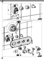
AR

10
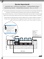
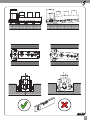
Lo spessore del muro nito deve essere compreso tra le misure di minimo e massimo indicate sull'etichetta
The thickness of the nished wall must be between the min and the max indicated on the label
Der Endabschnitt der Wand muss zwischen das Mindermaß und Maximalmaß, die auf dem Etikett sich benden, liegen
L’épaisseur du mur ni doit être comprise entre les mesures minimales et maximales indiquées sur l’étiquette
El espesór del muro tratado tiene que estar entre las medidas mínimas y máximas indicadas en la etiqueta
Толщина стены с отделкой должна быть в пределах минимума и максимума, указанных на этикетке
Fig_1
67.5 MIN
÷ 81.5 MAX mm
400 mm
MAX
- Lim ite de tolerance pour la surface
exterieure du carrelage
- Limiti di tolleranza pe r la superficie
finita delle piastrelle
MIN
- Adjustm e nt lim its for nished tiles surfaces
- Toleranzgrenze der iesenoberache
- Límites de tolerancia para la supercie
acabada del azulejo
- Пределы допуска для поверхности
с финишной отделкой
Parete piastrellata
Tiled wall
Geieste Wand
Mur carrelé
Pared azulejada
Стена с финишной отделкой
Quote importanti
Important sizes - Dimensions importantes - Wichtige Abmessungen
Tamaños importantes - Необходимые значения -

Fig_2
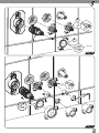
11
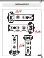
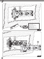
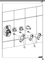
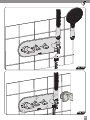
INSTALLAZIONE
Installation - Installation - Einbau - Instalación - Установка -

400 mm
220 mm
Fig_3
HOT water
1/2” GAS
COLD water
1/2” GAS
1/2” GAS
Fig_4
Spurgare sempre l’impianto prima di collegare i tubi di alimentazione.
É consigliabile installare all’ingresso dell’impianto un apposito filtro.
Always flush out the system before connecting it to the supply pipes.
The installation of a special inflow filter is recommended.
Muss die Rohrleitung vor dem Anschluss sorgfältig gespült werden.
Das Einbauen eines Filters am Eingang der Anlage ist zu empfehlen.
Purger l’installation avant de raccorder les conduits d’alimentation.
Il est conseillé d’installer, à l’entrée de l’installation, un filtre prévu à cet effet.
Purgue siempre la instalación antes de conectar los tubos de alimentación.
Se recomienda instalar un filtro adecuado en la entrada de la instalación.
Всегда обязательно прочищайте оборудование прежде, чем подвести к нему трубы водоснабжения.
Рекомендуется установить соответствующие фильтры на входе к смесителю.
12

Fig_5
13

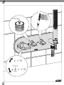
Fig_6
Usare canapa o teon
Use hemp or teon
Employer chanvre ou teon
Benutzen Sie Hanf oder Teon
Usar cáñamo o teón
Используйте лен или тефлон
Fig_7
20
14

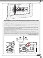
Per la progettazione, installazione e collaudo di impianti di alimentazione e distribuzione d’acqua
fredda e calda, fare riferimento alle normative vigenti: UNI EN 806 e UNI 9182
For designing, installing and testing supply and distribution systems of warm and cold water, refer to current
norms: UNI EN 806 and UNI 9182
Um die Versorgungs- und Verteilungsanlage für Warm- und Kaltwasser zu entwerfen, einbauen und prüfen,
muss man die geltenden Normen UNI EN 806 and UNI 9182 betreen
Pour concevoir, installer et tester une système d’alimentation et distribution de l’eau froide et chaude, on doit
se référer aux normes en vigueur: UNI EN 806 et UNI 9182
Para diseñar, instalar y probar sistemas de alimentación y distribución de agua fría y caliente, referirse a las
normas vigentes: UNI EN 806 y UNI 9182
При проектировании, установки и проведению тестирования на оборудовании по водоснабжению и
распределению горячей и холодной воды, придерживаться действующих нормативов: UNI EN 806 и UNI 9182
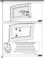
Fig_8
15

Fig_10
Fig_9
Si raccomanda l'applicazione di una guaina in polietilene impermeabilizzante (non inclusa nella confezione)
The application of a polyethylene waterproof sheath (not included in the packaging) is recommended
Es empehlt sich, um eine wasserdichte Hülle aus Polyäthylen (nicht in der Verpackung enthalten) einzubauen
Il est recommandé d’appliquer une gaine étanche en polyéthylène (non incluse dans le paquet)
Se recomienda el uso de una vaina en polietileno impermeabilizante (no incluida en la confección)
Рекомендуется применение водоотталкивающей прокладки из полиэтилена (не входит в комплектацию)
16

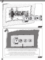
NELLA POSA DEL RIVESTIMENTO RISPETTARE LE INDICAZIONI DI MINIMO E MASSIMO
During the wall covering, follow the instructions about the minimum and maximum amounts
Halten sie sich beim verlegen der wandverkleidung an die angaben min und max
Pour la pose du revêtement, veiller à tenir compte des indications de minimum et maximum
Durante la colocación del revestimiento, respete las marcas de mínimo y máximo
При облицовке поверхности придерживаться минимальных и максимальных показателей
Fig_11
M
a
x
Attenzione: il rivestimento deve coprire no a lo del polistirolo
Warning: tiles must arrive until the edge of the polystyrene cover
Vorsicht: die Wandverkleidung muss bis zu dem Rand der Deckung aus Polystyrol gehen
Attention: le carrelage doit couvrir jusqu’au ras de la couverture en polystyrène
Atención: el cubrimiento tiene que cubrir hasta el hilo del poliestireno
Внимание: отделка должна доходить до края оболочки из полистирола
17

Fig_13
Fig_12
Tagliare la copertura in polistirolo a lo del rivestimento
Cut the polystyrene cover ush to the tiles level
Die Deckung aus Polystyrol bündig mit der Wandverkleidung scheiden
Couper la couverture en polystyrène au ras du carrelage
Cortar la cobertura en poliestireno a ras del cubrimiento
Срезать защитную крышку до уровня отделки
18

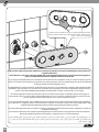
Fig_14
911
19

Fig_15
Spugna biadesiva - Biadhesive sponge - Doppelseitiger Klebeschwamm
Éponge adhésive double face -Esponja adhesiva doble - Клейкая губка
Nel calzare la piastra prestare attenzione ad evitare il contatto tra le parti metalliche per non rovinare le
superci in nitura.
I 4 fori devono essere ben centrati rispetto alle parti sporgenti dell’incasso. Successivamente spingere la
piastra in modo uniforme verso la parete evitando di inclinarla.
By inserting the wall plate, take care to avoid the contact between the metal parts to not to scratch the nishing of the
surface. The 4 holes must be perfectly centered on the sticking-out parts of the concealed body. Then push the wall plate
uniformly towards the wall avoiding to tilt it.
Bei Wandplatte Einstecken kümmern, die Berührung zwischen die Teile aus Metall zu vermeiden, damit die behandelte
Oberäche nicht zu kratzen. Die 4 Löcher müssen auf den hervorstehenden Teilen des Einbaukörpers perfekt zentriert
werden. Dann die Wandplatte gleichmäßig nach die Wand schieben, und vermeiden, sie zu neigen.
En insérant la plaque murale, faire attention à éviter le contact entre les pièces métalliques pour éviter de rayer la
nition de la surface. Les 4 trous doivent être parfaitement centrés sur les parties saillantes du corps encastré. Ensuite
pousser la plaque murale uniformément vers le mur en évitant de l'incliner.
Al insertar la placa de pared, tener cuidado de evitar el contacto entre las partes metálicas para no rayar el acabado
de la supercie. Los 4 agujeros deben ser perfectamente centrados en las partes salientes del cuerpo empotrado. Luego
empujar la placa de pared de manera uniforme hacia la pared evitando inclinarla.
При накладке наружной панели следует избегать контакта между металлическими сторонами, чтобы не
повредить отделку.
4 отверстия должны быть хорошо отцентрированы по отношению к выступающим частям встройки.
Далее равномерно продвиньте накладку в сторону стены, избегая перекосов.
12
20
La pagina si sta caricando...
La pagina si sta caricando...
La pagina si sta caricando...
La pagina si sta caricando...
La pagina si sta caricando...
La pagina si sta caricando...
La pagina si sta caricando...
La pagina si sta caricando...
La pagina si sta caricando...
La pagina si sta caricando...
La pagina si sta caricando...
La pagina si sta caricando...
La pagina si sta caricando...
La pagina si sta caricando...
La pagina si sta caricando...
La pagina si sta caricando...
-
 1
1
-
 2
2
-
 3
3
-
 4
4
-
 5
5
-
 6
6
-
 7
7
-
 8
8
-
 9
9
-
 10
10
-
 11
11
-
 12
12
-
 13
13
-
 14
14
-
 15
15
-
 16
16
-
 17
17
-
 18
18
-
 19
19
-
 20
20
-
 21
21
-
 22
22
-
 23
23
-
 24
24
-
 25
25
-
 26
26
-
 27
27
-
 28
28
-
 29
29
-
 30
30
-
 31
31
-
 32
32
-
 33
33
-
 34
34
-
 35
35
-
 36
36


Bossini Z00521+Z00135 Istruzioni per l'uso
- Tipo
- Istruzioni per l'uso
- Questo manuale è adatto anche per
in altre lingue
Documenti correlati
-
Bossini I00575 Istruzioni per l'uso
-
-
-
-
-
-
-
-
-