Pinecroft MLB4284HKD Istruzioni per l'uso
- Tipo
- Istruzioni per l'uso

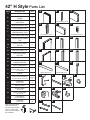
PART DESCRIPTION QTY
ADOOR STILE 2
BREINFORCEMENT
PLATES 4
CTOP/BOTTOM
DOOR RAILS 2
DREINFORCEMENT CLIP 4
ECENTER DOOR RAIL 1
F
CENTER RAIL
REINFORCEMENT CLIPS
2
JDOOR PANELS BOTTOM 9
J1 STARTER DOOR PANEL
TOP 1
J2
STARTER DOOR PANEL
BOTTOM
1
KDOOR PANELS TOP 9
L1
END DOOR PANEL TOP
1
L2 END DOOR PANEL
BOTTOM 1
MSIDE FINISHING STRIPS 2
NTOP/BOTTOM
FINISHING STRIPS 2
OROLLER BRACKETS 2
PHANDLE
(includes handle, bolts, washers,
nuts, wrenches)
1
RTRACK 1
R1 TRACK EXTENSION KIT
(included with 42" door only)
1
extension
kit
SSPACERS
for track install 5
TDOOR STOPS 2
VFLOOR GUIDE
with screws 1
WSAFETY SPACERS
with screws 2
XLAG BOLTS
for track installation 5
ZSCREWS
to attach Rails 22
42” H Style Parts List
A B C
DF
JJ1 J2
L1 L2
K
E
O
R1
TW
XZ
N
M
P R
V
S
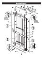
Pre-installed on Part A Pre-installed on Part A
Pre-installed on Part A
Stored inside Part A Stored inside Part C
Note: Part M are stored
inside of Part A and
Part N are stored inside
of Part C. Please take
them out before starting
the installation.
M
AN
C

Overview H Style 42”
O
OT
TS
R1
K
L2
K
L1
J
KKKK
JJJJJ
F
P
B
C
B
D
W
A
A
C
F
M
M
N
N
E
J
J1
J2
K
R
Z
X
X
V
K
K
J
J
Pre-drilled
holes for the
roller brackets
Pre-drilled
holes for the
roller brackets

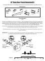
42” Barn Door Track Extension Kit
For the 42” Barn door, it is necessary to use the track extension included in your Barn door kit.
Kit Includes
2 Ea.
2 Ea.
2 Ea.
2 Ea.
2 Ea.
1 Ea.
To attach the extender, lay the track on the oor. Slip the extender (R1) onto the end of the track where
the door will be in the open position. It is important that the side of the track extender with the lip is
facing to the top. Begin tightening the 2 screws with the allen wrench (See Figures 1A & 1B). Use the
level to be sure the track and extender are straight and then fully tighten (See Figure 2) .
Turn the track and extender over, use the allen wrench to tighten the 2 remaining screws. Use the level
one more time to check the track is straight and then fully tighten the screws.
The extended track is now ready to install. Please refer to the Instructions for your Barn door kit for
proper installation.
IMPORTANT: It is important to read all instructions before you begin installation. A mounting board is
recommended and must be installed prior to hanging the track and door.
Figure 1A
Door opening to
the right
TopTop
Top
Level
Figure 2
1 Ea.
Tools Needed
Level
Figure 1B
Door opening to
the left
TopTo p
Top

Tools Needed
You will need a Pencil, Phillips head screwdriver, Wrench, Tape
measure, Drill, Assorted Drill bits (5/16” & 3/8”), 6” phillips
head bit (included in kit), 1/2” socket ratchet, 4ft Level, Rubber
mallet and Safety glasses.
Parts List
Make sure ALL parts are included before beginning.
NOTE:
It is very important to determine whether you will be installing
a Mounting Board prior to installing the track. If you do need to
install a Mounting Board, it MUST be installed rst.
(Mounting Board Not Included)
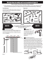
PVC Barn Door Assembly and Track Installation H Style 42”
Please read ALL instructions before you begin installation.
You MUST determine if you need a Mounting Board prior to doing ANY installation. Due to many overlapping factors
such as the location of wall studs, the weight of a Barn door and the various types of trim used in homes, we
recommend using a Mounting Board in all situations. Track must be installed into Solid Blocking or Head Casing.
Fig. 7
Fig. 7
1-1/2”
4-1/2”
2”
2”
17.75
INCH
17.75
INCH
17.75
INCH
17.75
INCH
2.5
INCH
H +
2 INCH
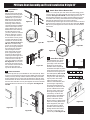
2. Determine Track
Location
On the same side where you made
your Height mark, measure 2-
½”
over from the door jamb and draw
a line so the 2 measurements
intersect. This will be the location
of the rst hole in the Track.
See Figure 1.
3. Insert Mounting Hardware
Drill pilot hole. Insert lag bolt (X) through the rst track hole, then
place the track spacer (S) through the bolt on back of the track.
Install the lag bolt with ½” socket ratchet. Do not tighten fully.
Swing the track up and use the level to ensure the track is straight.
Mark the remaining holes in the track. Drill remaining pilot holes.
At the other end of the track from where you installed your rst
bolt, slide the stopper (T) onto the track that is for the side where
the door will be in the closed position. Push it towards the middle
of the track. Install a bolt and spacer at this end of the track. Slide
the stopper to the other end of the track so it is between the rst
and second holes in the track. Install the remaining bolts and
spacers. Go back and full tighten the rst bolt. Slide the remaining
stopper onto the other end of the track. Do not set either stopper
at this point. Refer to Figures 2A, 2B & 2C.
Figure 1
NOTE NOTE
5 Ea.
5 Ea.
1 Ea.
1 Ea. 2 Ea.
22 Ea.
2 Ea.
2 Ea.
1. Measure for Track Height
In order to determine the proper Height for your Barn Door
Track, add 2” to the height of the door being installed. Locate
and mark this height on the wall (or mounting board) on the
side of the door jamb where the door would be in the closed
position. See Figure 1.
2 Ea.
5 Ea.
5 Ea.
2 Ea.
2 Ea.
2 Ea.
1 Ea.
5 Ea.
1 Ea.
Fig. 2A
Fig. 2B
Fig. 2C
Figure 2A
Masonry Application
Figure 2B
Mounting Board/Stud Application
Fig. 2A
Fig. 2B
Fig. 2C
Fig. 2A
Fig. 2B
Fig. 2C

PVC Barn Door Assembly and Track Installation H Style 42”
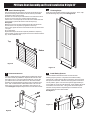
4. Attach Stile to
Top Rail
Reinforcement Plate (Part B)
and Reinforcement Clip (Part
D) are pre-installed into door
stile(Part A). Lay one of the
Stiles (A) onto work surface.
Make sure the side with the
large holes in the channel
are facing outward and the
channel with the pre-installed
reinforcement clips is facing
inward. Please note: the pre-
drilled holes in the surface of
the stile will be the Top of
your door. (see door overview
page for reference). Insert a
4” screw (Part Z) to each of
the two holes at outer groove
of upper stile side and make
sure the two screws are fully
inserted. See Figure 4A and
4B. Make sure that the big
groove at one side of Top Rail
(Part C) is facing upward and
the small groove at another
side is facing downward.
Place horizontally Top Rail
(Part C) against the upper
end of door stile and simul-
taneously let both upper and
lower holes at the top rail end
receive the two screw tips
come from the door stile side.
See Figure 4C. Once screws
and holes are placed in posi-
tion, drive the screws into the
holes until door stile and
top rail are ush and secure.
5. Install Center Rail
The black clip (Part F) is pre-installed into door stile (Part A). Place
2 of the 4 inch screws (Part Z) into the pre-drilled holes in the stile,
making sure they are fully inserted. Place horizontally Center Rail
(Part E) against the two screws and simultaneously let both upper
and lower holes at center rail end receive the two screw tips come
from the door stile side. Once in place tighten the screws until stile
and rail are ush and secure. Do not overtighten. See Figure 5A
and 5B.
7. Insert Door Panels
Take the Starter Door Panel
Bottom (Part J2) and let its
open edge is face downward.
Slide it down horizontally
between Center rail (Part E)
and Bottom Rail (Part C) as the
lower panel section of the door
and insert it into the groove of
Door Stile (Part A). See 7A, 7B
and 7C. Make sure that it ts
snug into door stile and gently
tap into place with rubber
mallet if necessary. Next,
take Door Panel Bottom (Part
J) with tongue edge facing
downward and slide it down
horizontally to insert it into the
groove of Starter Door Panel
(Part J2). Again, make sure it
ts snug and tap into place
if necessary. Continue with
remaining Door Panel Bottom
(Part J) at lower door panel
section is End Door Panel
Bottom )Part L2). Repeat these
steps for inserting Starter Door
Panel Top (Part K) into upper
door panel section located
between Center Rail (Part C).
Ending with End Door Panel
Top (Part L1) See door over-
view for layout. See Figure 7D.
6. Attach Door Stile to Bottom Rail
Bottom
Rail
Middle
Rail
TopRail
Side Stile
Starter Panel
End Panel
Bottom
Rail
Middle
Rail
TopRail
Side Stile
Starter Panel
End Panel
Bottom
Rail
Middle
Rail
TopRail
Side Stile
Starter Panel
End Panel
Figure 4A
Figure 4B
Figure 5A
Figure 6A
Figure 7A
Fig. 2A
Fig. 2B
Fig. 2C
Figure 4C
Figure 5B
Insert a 4” screw (Part Z) to each of the two holes at big groove
of lower side of door stile and make sure the two screws are fully
inserted. See Figure 6A and 6B. Let the small groove at one
side of Bottom Rail (Part C) is facing upward and the big groove
at another side is facing downward. Place horizontally Bottom
Rail (Part C) against the lower end of door stile and
simultaneously let both upper and lower holes at bottom rail end
receive the two screw tips come from the door stile side. Figure
6C. Once in place tighten the screws until stile and rail are ush
and secure.
Figure 6B
Figure 7B
Figure 7C
Figure 7D
Figure 6C

PVC Barn Door Assembly and Track Installation H Style 42”
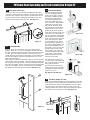
8. Attach Remaining Stile
Take remaining Stile (A) and make sure the side with the large holes in
the channel is facing outward and the channel with the pre-installed
reinforcement clips is facing inward.
Reminder: the end with the pre-drilled holes in the surface of the stile is
the Top of your door. (see door overview page for reference).
Insert 2 of the 4” screws (Part Z) into the holes in the outside of the stile
channel at the top of the stile where it meets the Top rail (C).
See Figure 8.
Make sure the screws are fully inserted into the stile channel and the
extrusion holes in the Top rail line up against the screw tips.
Once in place, tighten the screws until the stile and the Top rail are about
1/2” apart.
Do not fully tighten.
Repeat these steps at the Center rail (Part E) and Bottom rail (Part C)
Once complete, go back and fully tighten the screws at all three locations
(Top, Center and Bottom rails).
9. Install Roller Brackets
The door stiles (A) have pre-drilled holes located at the top for
the roller bracket (O) installation. Separate the bolts from the
decorative nuts on one of the roller brackets (O). Line up the
pre-drilled holes in the stile with those on the roller bracket.
Reinsert the washers/bolts through the hole in the back of the
door. Then re-attached the washer/decorative nuts onto the
bolts on the front of the door and tighten with wrench to se-
cure. See Figure 9. Repeat steps for the second roller bracket.
10. Finishing Strips
Snap the top and bottom nishing strips into place. Then, snap
the side nishing strips into place. See Figure 10.
Figure 9
Figure 8
Figure 10
Top
Bottom
11. Install Safety Spacers
Once the Roller brackets have been secured and the
nishing strips in place, it is important to install the Safety
spacers (W). These spacers help to protect the door from being
bumped o of the track. With the door laying at in a safe and
secure position, place one of the two spacers approximately 2”
to the inside of one of the roller brackets. Place slightly o center
towards the front of the door. Using a drill, secure the spacer
with the screw provided. Repeat steps to install the second
spacer inside the other roller bracket.
See Figure 11.
Figure 11
2
INCH
2
INCH
1-1/2”
Bottom
Rail
Middle
Rail
TopRail
Side Stile
Starter Panel
End Panel

12. Place door onto Track
Position the door over the opening and slightly tilt the bottom
of the door outward away from the wall. Set the rollers securely
onto the track. Once the door is safely mounted and is secure,
turn the 2 safety spacers 180 degrees towards the wall. This
positions them properly under the track. See Figure 12.
PVC Barn Door Assembly and Track Installation H Style 42”
2
INCH
2
INCH
1-1/2”
Figure 12
13. Install Handle
Measure up 52” from the bottom of the door and mark that
location. Measure 1 3/4” in from the edge of the stile and mark
this spot. Drill a hole through the stile at the intersection of these
2 marks. Place the handle on the door and insert one of the
handle bolts into the top hole in the handle. Put the washer and
nut onto the backside of the door and tighten the nut. Do not
tighten fully at this point.
Using a level to make sure the handle is plumb, mark the location
of the bottom hole in the handle. Move the handle aside and drill
the second hole through the stile. Put the remaining bolt through
the hole in the handle. Put the washer and nut onto the backside
of the door and tighten the nut. Use the wrenches provided to
fully tighten the bolts and secure the handle. See Figure 13.
2
INCH
2
INCH
1-1/2”
14. Install Floor Guide
The oor guide (V) keeps the
door from swinging outward
away from the wall. To locate
the proper installation position
for the guide, slide the door
into the closed position and
mark the outside edge of the
door on the oor. Take the oor
guide and remove the screw
and washer. Set them aside
with the top piece of the guide.
Take the bottom piece of the
guide and place it on the oor
under the outer edge of the door
about 1⁄2” in from the edge of
the door. The back of the guide
will sit between the wall and the
back of the door. Move the door
to the open position to make
sure the guide is in the proper
position. Whether the door is in
the open or closed position, the
door should NEVER leave the
door guide. Once you have the
proper position for the guide,
move the door out of the way
and mark the back hole location
in the guide. make sure the
guide is plumb and mark the
front hole in the guide.
Pre-drill holes if necessary for
your oor type. Using a drill and
the screws provided, secure the
Door guide to the oor.
Re-insert the top piece of the
guide with the screw and wash-
er, setting the width of the oor
guide to 1 1/2 to 2”.
See Figures 14A-14B-14C.
15. Set Door Stops on Track
Make sure the rubber stoppers are facing inward on each side.
Move the door to the closed position and slide the Door stop
to desired location. Using the provided Allen wrench, tighten
the screws in the door stop to secure it in into place. Then
carefully glide the door into the fully open position and repeat
the steps for the remaining Door stop. See gure 15.
Figure 13
Figure 15
2
INCH
2
INCH
1-1/2”
(T)
Figure 14A
Figure 14B
Figure 14C
-
 1
1
-
 2
2
-
 3
3
-
 4
4
-
 5
5
-
 6
6
-
 7
7


