
CAME S.p.A.
Via Martiri Della Libertà, 15
31030 - Dosson di Casier
Treviso - Italy
Agata VCB-L
Lb
La
MAX 8
XDV/304
L1 L2
Lb
Lb
L3
VA/01
Lc
Lithos
ThangramThangramThangram
VAS/101
VAS/100MHVAS/100MH VAS/100MHVAS/100MH
N° Slave
L1 L2
Lb
La
L3
N° Master
VA/01
XDV/304
N° Slave
Lb
La
Lc
N° Master
Lithos
ThangramThangramThangram
XDV/304
VAS/101
N° Slave
L1 L2
Lb
La
L3
N° Master
VA/01
XDV/304
N° Slave
Lb
La
Lc
N° Master
Lithos
ThangramThangramThangram
XDV/304
VAS/101
– +
AL B– +
– +
AL B– +
BUS
LOCAL
BUS
LOCAL
– +
AL B– +
– +
AL B– +
BUS
LOCAL
BUS
LOCAL
3 5 6
2
1
2
1 4
10
11
7
12
13
14
15
16
M1
CL.
RES.
BUS
LOCAL
BUS
LOCAL
M/S
– +
AL B– +
B
E
H
C
F
D
G
I
3sec
... beep!
3sec
... beep!
3sec
... beep!
3sec
... beep!
3sec
... beep!
3sec
... beep!
3sec
... beep!
3sec
... beep!
A
3sec
... beep!
CL.RES
XDV/304
CL.RES CL.RES
1 2 3
M/S MASTER SLAVEM/S
Fam. Rossi
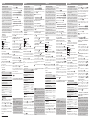
VCM/1D UTP CAT5
N° Master 4 3 2 1 3 2 1
N° Slave 4 5 6 7 0 6 7
VCM/1D VCM/2D UTP/CAT 5
La+Lb ≤100 m – ≤60 m
L1, L2, L3 – ≤100 m –
L1+L2+ L3 – ≤300 m –
La + Lb + L1 (L2, L3) ≤150 m
La + Lb + L1 + L2 + L3 ≤600 m
VCM/1D UTP CAT5
N° Master 3 2 1 1
N° Slave 0 3 7 3
VCM/1D VCM/2D UTP/CAT 5 2x1mm22x2,5mm2
La+Lb ≤100 m – ≤100 m – –
Lc – – – ≤25 m ≤60 m
La + Lb + Lc ≤100 m
VCM/1D VCM/2D UTP/CAT 5 2x2,5mm2
La+Lb ≤100 m – ≤100 m –
Lc ≤40 m – – ≤100 m
L1, L2, L3 – ≤100 m – –
L1 + L2 + L3 – ≤300 m – –
La + Lb + L1 (L2, L3) ≤150 m
La + Lb + L1+ L2 + L3 ≤600 m
8 9
FB00853M4A - ver. 1 - 07/2017
FB00853M4A
IT
Italiano
EN
English
FR
Français
RU
Pусский

FB00853M4A - ver. 1 - 07/2017
ITALIANO
Avvertenze generali
• Leggere attentamente le istruzioni, prima di
iniziare l’installazione ed eseguire gli interventi
come specificato dal costruttore.
• L’installazione, la programmazione, la mes-
sa in servizio e la manutenzione del prodot-
to deve essere eettuata solo da personale
tecnico qualificato ed opportunamente ad-
destrato nel rispetto delle normative vigenti
ivi comprese le osservanze sulla prevenzione
infortuni.
• Prima di eettuare ogni operazione di pulizia
o di manutenzione, togliere l’alimentazione.
• L’apparecchio dovrà essere destinato solo
all’uso per il quale è stato studiato.
• Il costruttore non può comunque essere con-
siderato responsabile per eventuali danni deri-
vanti da usi impropri, erronei ed irragionevoli.
Descrizione
Derivato interno videocitofonico intercomuni-
cante alimentabile localmente.
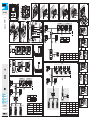
Morsettiera M1
AL Ingresso allarme
–+ Chiamata da pianerottolo
B Ingresso linea BUS
– + Alimentazione locale
Resistenza di fine linea (CL.RES) .
Il ponticello deve essere inserito solo nell'ultimo
dispositivo della linea.
Selettore master/slave (M/S) .
Se due o più derivati sono stati configurati per
rispondere ad una stessa chiamata, solo sul/sui
derivati master viene visualizzata l'immagine in
anteprima del chiamante.
Selettore fonte di alimentazione .
Posizione del ponticello con dispositivo ali-
mentato localmente.
Posizione del ponticello con dispositivo ali-
mentato da BUS.
Dati tecnici
Tipo Agata
VCB-L
Alimentazione locale (VDC) 14÷18
Assorbimento massimo con
alimentazione locale (mA) 135
Alimentazione da BUS (VDC) 15 ÷ 20
Assorbimento massimo con
alimentazione da BUS (mA) 175
Assorbimento singolo LED (mA) 1
Temperatura di stoccaggio (°C) -25 ÷ +70
Temperatura di funzionamento (°C)
+5 ÷ +40
Grado IP IP 30
Standard video PAL/NTSC
Display LCD TFT (pollici) 3,5
Installazione
• Premere il pulsante ①; sganciare il sup-
porto dal dispositivo facendolo scorrere ②.
• Fissare il supporto alla scatola da incasso:
tonda Ø 60mm , rettangolare 503 ,
rettangolare 506E oppure alla scatola incas-
so di Ophera (PHI). Utilizzare le viti in dotazione,
rispettare l’indicazione TOP ed evitare il serrag-
gio eccessivo delle viti.
Installare il dispositivo ad un’altezza adeguata
all’utente.
• Eseguire i collegamenti e agganciare il dispo-
sitivo al supporto .
• Per sganciare l’apparecchio dal supporto pre-
mere il pulsante e sollevare il dispositivo .
Limiti dell'impianto
L’accensione contemporanea di 4 monitor è
possibile solo in impianti Mono/Bifamiliari con
DVC+VA/01 (schema ).
Derivati alimentati localmente.
Configurazione melodie
☞ Bisogna eseguire, in successione, tutte
le fasi di programmazione descritte di se-
guito:
1-Ingresso in Programmazione.
Premere e mantenere premuto il pulsante per
3 secondi. Un breve segnale acustico e il LED
lampeggiante confermano l’ingresso in pro-
grammazione .
2-Programmazione della melodia associata
alla chiamata dal posto esterno.
Per ascoltare in sequenza le melodie premere
il tasto .
Per selezionare la melodia ed uscire dalla pro-
grammazione, premere il pulsante .
Per selezionare la melodia e proseguire con la
programmazione premere il tasto D.
3- Programmazione della melodia associata
alla chiamata dal pianerottolo.
Per ascoltare in sequenza le melodie premere il
tasto E.
Per selezionare la melodia ed uscire dalla pro-
grammazione premere il tasto .
Per selezionare la melodia e proseguire con la
programmazione premere il tasto .
4- Programmazione del numero di squilli di
chiamata.
Premere il tasto tante volte quanti sono gli
squilli desiderati (da 1 a 6 squilli) .
Dopo 3 secondi dall’ultima pressione del tasto
verrà riprodotta la chiamata selezionata per il
numero di squilli prescelto.
Per uscire dalla programmazione premere il ta-
sto .
☞ Per la programmazione della chiamata,
vedere la documentazione dei posti esterni.
Il prodotto è conforme alle direttive di riferi-
mento vigenti.
Dismissione e smaltimento. Non disperdere
nell’ambiente l’imballaggio e il dispositivo alla
fine del ciclo di vita, ma smaltirli seguendo le
norme vigenti nel paese di utilizzo del prodot-
to. I componenti riciclabili riportano simbolo e
sigla del materiale.
I DATI E LE INFORMAZIONI INDICATE IN QUESTO MANUALE
SONO DA RITENERSI SUSCETTIBILI DI MODIFICA IN QUALSIA-
SI MOMENTO E SENZA OBBLIGO DI PREAVVISO. LE MISURE,
SE NON DIVERSAMENTE INDICATO, SONO IN MILLIMETRI.
ENGLISH
General precautions
• Read the instructions carefully before begin-
ning the installation and carry out the actions
as specified by the manufacturer.
• The installation, programming, commission-
ing and maintenance of the product must be
carried out only by qualified technical person-
nel, correctly trained with regard to respecting
the regulations in force, including the imple-
mentation of accident prevention measures.
• Before carrying out any cleaning or mainte-
nance operation, disconnect the power supply.
• The equipment must be destined only for
the use for which it was designed.
• The manufacturer declines all liability for any
damage as a result of improper, incorrect or
unreasonable use.
Description
Locally powered intercom internal video receiv-
er.
Terminal board M1
AL Alarm input
–+ Doorbell
B BUS line input
– + Local power supply
Closing resistance (CL.RES) .
The jumper should be inserted in the last device
in the line only.
Master/Slave selector (M/S) .
If one or more receivers have been configured to
respond to the same call, the preview image of
the caller is shown only on the master device(s).
Power source selector .
Position of the jumper with locally powered
device.
Position of the jumper with BUS-powered
device.
Technical data
Type Agata
VCB-L
Local power supply (VDC) 14-18
Maximum consumption with local
power supply (mA) 135
Power supply by BUS (VDC) 15 - 20
Maximum consumption with BUS
power supply (mA) 175
Single LED consumption (mA) 1
Storage temperature (°C) -25 to +70
Operating temperature (°C)
+5 to +40
IP Rating IP 30
Video standard PAL/NTSC
LCD TFT display (inches) 3.5
Installation
• Press the ① button; unhook the support
from the device, sliding it downwards ②.
• Fasten the support to the recessed box:
round 60 mm Ø , 503 rectangular ,
506E rectangular or the Ophera (PHI) re-
cessed box. Use the screws provided, observe
the direction marked “TOP” and avoid overtight-
ening the screws.
Install the device at a suitable height for the
user.
• Make the connections and fit the device onto
the support .
• To unfasten the unit from the support press
the button and lift the device .
System limits
4 monitors can be turned on at the same time
with single/two-family systems with DVC+-
VA/01 only ().
Locally powered receivers.
Configuring melodies
☞ Perform each of the following program-
ming-steps, in succession.
1-Enter programming mode.
Press and keep pressed the button for three
seconds. A buzzing sound and a flashing LED
confirm that you have entered the programming
mode .
2-Programming the melody associated to
the call from the entry panel.
To listen to the melodies in sequence, press
button .
To select the melody and exit the programming
mode, press button .
To select the melody and continue in program-
ming mode, press button D.
3- Programming the melody associated to a
call from the landing.
To listen to melodies in sequence, press button
E.
To select the melody and exit the programming
mode, press button .
To select the melody and continue in program-
ming mode, press button .
4-Programming the number of rings per call.
Press the button as many times as the number
of rings you want (from 1 to 6 rings) .
After three seconds from the last pressing of a
button, the call will be made with the number of
selected rings.
To exit the programming mode, press button
.
☞ To program a call, see the literature for
entry panels.
- This device complies with Part 15 of
the FCC Rules. Operation is subject to the
following two conditions: (1) this device may
not cause harmful interference and (2) this
device must accept any interference received,
including interference that may cause unde-
sired operation.
This product complies with the relevant direc-
tives in force.
Decommissioning and disposal. Dispose of
the packaging and the device at the end of its
life cycle responsibly, in compliance with the
laws in force in the country where the prod-
uct is used. The recyclable components are
marked with a symbol and the material's ID
marker.
THE DATA AND INFORMATION SHOWN IN THIS MANUAL ARE
TO BE CONSIDERED AS SUBJECT TO CHANGE AT ANY TIME
AND WITHOUT THE NEED FOR ANY ADVANCE WARNING.
MEASUREMENTS, UNLESS OTHERWISE INDICATED, ARE IN
MILLIMETRES.
FRANÇAIS
Instructions générales
• Lire attentivement les instructions avant de
commencer l'installation et eectuer les inter-
ventions comme indiqué par le fabricant.
• L'installation, la programmation, la mise en
service et l'entretien du produit ne doivent
être eectués que par un personnel technique
qualifié et convenablement formé, conformé-
ment aux normes légales en vigueur, y com-
pris les dispositions concernant la prévention
des accidents.
• Avant toute opération de nettoyage ou
d'entretien, veuillez mettre le dispositif hors
tension.
• L'appareil doit être uniquement utilisé dans
le but pour lequel il a été conçu.
• Le fabricant ne peut toutefois être tenu pour
responsable des éventuels dommages qui
naîtraient d'une utilisation erronée ou dérai-
sonnable.
Description
Poste interne du portier vidéo intercommunicant
pouvant être alimenté localement.
Bornier M1
AL Entrée alarme
–+ Appel depuis palier
B Entrée ligne BUS
– + Alimentation locale
Résistance de fin de ligne (CL.RES) .
Le cavalier ne doit être inséré que dans le der-
nier dispositif de la ligne.
Sélecteur master/slave (M/S) .
Si deux ou plusieurs postes ont été configurés
pour répondre à un même appel, l'image en
avant-première de l'appelant ne s'achera que
sur le/les poste/s master.
Sélecteur de la source d'alimentation .
Position du cavalier avec dispositif alimenté
localement.
Position du cavalier avec dispositif alimenté
depuis BUS.
Données techniques
Type Agata
VCB-L
Alimentation locale (VDC) 14÷18
Absorption maximum avec
alimentation locale (mA) 135
Alimentation depuis BUS (VDC) 15 ÷ 20
Absorption maximum avec
alimentation depuis BUS (mA) 175
Courant absorbé par LED (mA) 1
Température de stockage (°C) -25 ÷ +70
Température de fonctionnement
(°C)
+5 ÷ +40
Indice IP IP 30
Standard vidéo PAL/NTSC
Écran LCD TFT (pouces) 3,5
Installation
• Appuyer sur le bouton ① ; décrocher le
support du dispositif en le faisant glisser ②.
• Fixer le support au boîtier à encastrer :
rond Ø 60mm , rectangulaire 503 ,
rectangulaire 506E ou au boîtier à encastrer
de Ophera (PHI). Utiliser les vis fournies, respec-
ter l'indication TOP et éviter un serrage excessif
des vis.
Installer le dispositif à une hauteur adaptée à
l'utilisateur.
• Eectuer les branchements et accrocher le
dispositif au support .
• Pour décrocher l'appareil du support, appuyer
sur le bouton et soulever le dispositif .
Limites de l'installation
L’allumage simultané de 4 écrans n'est possible
que sur les installations Unifamiliales/Bifami-
liales avec DVC+VA/01 (schéma ).
Postes alimentés localement.
Configuration des mélodies
☞ Eectuer, l’une après l’autre, toutes les
phases de programmation décrites ci-après :
1-Entrée en mode programmation.
Appuyer sur le bouton et le laisser enfoncé
pendant 3 secondes. Un signal sonore bref et
le clignotement de la LED confirment l’entrée en
mode programmation .
2-Programmation de la mélodie associée à
l’appel provenant du poste extérieur.
Pour écouter les mélodies l’une après l’autre,
appuyer sur la touche .
Pour sélectionner la mélodie et sortir de la pro-
grammation, appuyer sur le bouton .
Pour sélectionner la mélodie et poursuivre la
programmation, appuyer sur la touche D.
3- Programmation de la mélodie associée à
l’appel provenant du palier.
Pour écouter les mélodies l’une après l’autre,
appuyer sur la touche E.
Pour sélectionner la mélodie et sortir de la pro-
grammation, appuyer sur la touche .
Pour sélectionner la mélodie et poursuivre la
programmation, appuyer sur la touche .
4- Programmation du nombre de sonneries
de l’appel.
Appuyer sur la touche autant de fois que le
nombre de sonneries souhaité (de 1 à 6 son-
neries) .
Au bout de 3 secondes à compter du dernier
enfoncement de la touche, l’appel sélectionné
sera reproduit selon le nombre de sonneries
choisi.
Pour sortir du menu de programmation, appuyer
sur la touche .
☞ Pour la programmation de l’appel, voir la
documentation des postes extérieurs.
Le produit est conforme aux directives de réfé-
rence en vigueur.
Démantèlement et élimination. Ne pas jeter
les emballages et l'appareil dans la nature à la
fin du cycle de vie, mais veuillez les éliminer
conformément à la réglementation en vigueur
dans le Pays d'utilisation du produit. Les com-
posants recyclables portent le symbole et le
sigle du matériau.
LES DONNÉES ET INFORMATIONS DE CE MANUEL SONT
CONSIDÉRÉES COMME SUSCEPTIBLES DE MODIFICATIONS
À TOUT MOMENT ET SANS PRÉAVIS. LES MESURES, SAUF
AUTRES INDICATIONS, SONT EXPRIMÉES EN MILLIMÈTRES.
РУССКИЙ
Общие предупреждения
• Перед началом работ по установке вни-
мательно ознакомьтесь с инструкциями и
выполните установку согласно рекоменда-
циям производителя.
• Установка, программирование, ввод в
эксплуатацию и обслуживание продукта
должны выполняться только квалифициро-
ванным и специально обученным персона-
лом ссоблюдением действующих стандар-
тов, включая требования по охране труда и
технике безопасности.
• Перед очисткой или техническим обслу-
живанием следует отсоединять устройство
от источника электропитания.
• Устройство следует использовать только
вцелях, для которых оно предназначено.
• Производитель не несет никакой от-
ветственности за любые повреждения,
возникшие в результате неправильного,
некорректного или неоправданного ис-
пользования.
Описание
Абонентское устройство видеодомофонии с
функцией интеркома и локальным питанием.
Клеммная колодка М1
AL Питание
–+ Вход дверного звонка
B Вход шины
– + Локальный источник питания
Резистивная концевая заглушка линии
(CL.RES) .
Перемычка должна быть установлена только
на последнее устройство линии.
Переключатель мастер/подчиненное
устройство (M/S) .
В случае вызова нескольких абонентских
устройств одновременно аудио- и видеос-
вязь будет активирована только для веду-
щего (MASTER) устройства (только аудио на
остальных).
Селектор источника питания .
Положение перемычки с устройством,
имеющим локальное питание.
Положение перемычки с устройством,
питаемым от шины.
Технические данные
Тип Agata VCB-L
Локальный источник питания
(пост. ток) 14÷18
Максимальное потребление
при локальном питании (мА) 135
Питание от шины (пост. ток) 15 ÷ 20
Максимальное потребление
при питании от шины (мА) 175
Потребление отд.
Светодиода (мА) 1
Температура хранения (°C) -25 ÷ +70
Рабочая температура (°C)
+5 ÷ +40
Класс IP IP 30
Видео стандарт PAL/NTSC
Дисплей LCD TFT (дюймы) 3,5
Установка
• Нажмите клавишу ①; снимите крон-
штейн с устройства, слегка сдвинув ее ②.
• Закрепите кронштейн на встраиваемой
монтажной коробке:
круглой Ø 60мм , прямоугольной 503 ,
прямоугольной 506E или встраиваемой ко-
робке Ophera (PHI). Используйте прилагаемые
винты, соблюдайте указание ВЕРХ и избегай-
те чрезмерного затягивания винтов.
Устройство следует устанавливать на вы-
соте, удобной для пользователя.
• После подсоединения, установите устрой-
ство на кронштейн .
• Чтобы отсоединить устройство от опоры,
нажмите на клавишу и поднимите устрой-
ство .
Ограничения системы
Одновременное включение 4 мониторов воз-
можно только для систем на Одну/Две семьи
с DVC+VA/01 (схема ).
Абонентские устройства с локальным
питанием.
Настройка мелодий
☞ Необходимо последовательно
выполнить все этапы программирования,
описанные ниже:
1. Вход в режим программирования.
Нажмите и удерживайте кнопку в
течение 3 секунд. Короткий звуковой сигнал
и мигающий светодиодный индикатор
подтвердят вход в режим программирования
.
2. Программирование мелодии вызова с
вызывной панели.
Для последовательного прослушивания
мелодий нажмите кнопку .
Для выбора мелодии и выхода из режима
программирования нажмите кнопку .
Для выбора мелодии и продолжения
программирования нажмите кнопку D.
3. Программирование мелодии дверного
звонка.
Для последовательного прослушивания
мелодий нажмите кнопку E
Для выбора мелодии и выхода из режима
программирования нажмите кнопку .
Для выбора мелодии и продолжения
программирования нажмите кнопку .
4. Программирование количества
звонков во время вызова.
Нажмите кнопку столько раз, сколько
звонков требуется для вызова (от 1 до 6) .
Спустя 3 секунды после последнего
нажатия клавиши мелодия вызова будет
воспроизведена заданное количество раз.
Для выхода из режима программирования
нажмите кнопку .
☞ Информация о программировании
вызовов приведена в документации на
вызывные панели.
Изделие соответствует применимым ди-
рективам.
Прекращение использования и утилиза-
ция. Не выбрасывайте упаковку и устрой-
ство в конце жизненного цикла, утилизи-
руйте их в соответствии с действующими
в стране использования продукта нормами.
Компоненты, пригодные для повторного
использования, отмечены специальным
символом с обозначением материала.
ДАННЫЕ И ИНФОРМАЦИЯ, СОДЕРЖАЩАЯСЯ В ДАННОМ
РУКОВОДСТВЕ, МОГУТ БЫТЬ ИЗМЕНЕНЫ В ЛЮБОЕ ВРЕ-
МЯ БЕЗ ПРЕДВАРИТЕЛЬНОГО УВЕДОМЛЕНИЯ. РАЗМЕРЫ,
ЕСЛИ НЕ УКАЗАНО ИНОЕ, В МИЛЛИМЕТРАХ.
-
 1
1
-
 2
2


in altre lingue
- English: CAME AGATA Installation guide
Documenti correlati
-
CAME AGATA V-VC-VCB Guida d'installazione
-
-
-
-
-
-
-
-
-