
FA01463M4A
02/2021
806SL-0290
(SELT2BDG)
IT Italiano
EN English
FR Français
RU Русский
CAME S.p.A.
Via Martiri Della Libertà, 15
31030 - Dosson di Casier
Treviso - Italy
A
70
73
93
16
77
60
B
A B
BUS
BUS
Ø 90
1
5
1 2 3 4
1 2 3 4
2
1 2 3 4
1 2 3 4
1 2 3 4
1 2 3 4
4
1 2 3 4
1 2 3 4
1 2 3 4
1 2 3 4
R800
S0002P / S0002M
S0001 / S0002 / S0004
C
Avvertenze generali per
l'installatore
Leggere attentamente le istruzioni
prima di iniziare l’installazione
ed eseguire gli interventi come
specificato dal costruttore. •
L’installazione, la programmazione,
la messa in servizio e la
manutenzione devono essere
effettuate da personale qualificato
ed esperto e nel pieno rispetto
delle normative vigenti. • Prima di
effettuare qualunque operazione di
pulizia, manutenzione o sostituzione
di parti, togliere l’alimentazione al
dispositivo. • Il prodotto deve essere
destinato solo all’uso per il quale è
stato espressamente studiato e
ogni altro uso è da considerarsi
pericoloso. • Il produttore non può
essere considerato responsabile
per eventuali danni causati da usi
impropri, erronei ed irragionevoli.
Se il dispositivo non è alimentato
da quadro CAME, assicurarsi che
l'alimentazione fornita al dispositivo
sia provvista di limitazione in corrente
non superiore a 1,5 A.
Dismissione e smaltimento
Non disperdere nell’ambiente
l’imballaggio e il dispositivo alla fine
del ciclo di vita, ma smaltirli seguendo
le norme vigenti nel paese di utilizzo
del prodotto. I componenti riciclabili
riportano simbolo e sigla del materiale.
I DATI E LE INFORMAZIONI INDICATE
IN QUESTO MANUALE SONO DA
RITENERSI SUSCETTIBILI DI MODIFICA
IN QUALSIASI MOMENTO E SENZA
OBBLIGO DI PREAVVISO.
LE MISURE, SE NON DIVERSAMENTE
INDICATO, SONO IN MILLIMETRI.
Descrizione
SELT2BDG - Selettore a tastiera
BUS CXN da incasso, 12 tasti, con
retroilluminazione blu. Colore grigio,
RAL7024.
Dati tecnici
MODELLI SELT2BDG
Potenza (W) 0,6
Corrente assorbita
(mA) 40
Temperatura
d’esercizio (°C) -20 ÷ +55
Grado di protezione
(IP) 54
Classe di isolamento III
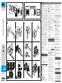
Descrizione delle parti
A
1
Contenitore
2
Guarnizione
3
Telaio frontale
4
Viti UNI6955 3.9 x 19
5
Gommino di tenuta
6
Coperchio di protezione della
scheda
7
Tastiera
8
Copertura frontale
9
LED di segnalazione stato
Dimensioni
B
Installazione
C
Le varie tipologie di collegamento
di più selettori sono indicati nel
ITALIANO
manuale di installazione del quadro
comando.
Configurazione BUS
Si raccomanda l'utilizzo di un
cavo FROR 2 x 0,5 mm con lunghezza
max. 50 m dalla scheda elettronica.
Non utilizzare un cavo
schermato.
Collegare il selettore sul morsetto BUS.
È possibile collegare fino a un max. di
7 selettori BUS (a tastiera, transponder,
bluetooth o a chiave).
Se nell'impianto sono collegati
più selettori BUS, impostare un
indirizzo univoco, per ogni selettore,
utilizzando i DIP 1 2 3. Vedi figura
9
.
Se due selettori hanno lo
stesso indirizzo sul BUS, la
retroilluminazione si accende di rosso
lampeggiante.
Configurazione R800 -
S0002M/P - S0001/2/4
Si raccomanda l’utilizzo di
un cavo FROR 2 x 0,5 mm con
lunghezza max. 30 m dalla scheda
elettronica.
Collegare il selettore sui morsetti
A-B.
Posizionare i DIP 1 2 3 in OFF. Vedi
figura
10
.
Numero di selettori collegabili
Scheda
interfaccia DIP 4 Numero di
selettori
R800 /
S0002M
ON 2
OFF 3
R800 V2 /
S0002P
ON 4
OFF 4
S0001 /
S0002 /
S0004
ON 0
OFF 2
Retroilluminazione selettore
Configurazione R800 -
S0002M/P - S0001/2/4
Posizionare il DIP 4 in ON per attivare
la retroilluminazione del selettore.
Configurazione BUS
Posizionare il DIP 4 in ON per
attivare e regolare l’intensità della
retroilluminazione del selettore.
Procedere nel seguente modo:
- premere il tasto (#) per 5 secondi;
- premere il tasto (1) per
attivare l’intensità minima di
retroilluminazione, tasto (2)
per attivare l’intensità media di
retroilluminazione (default) o tasto (3)
per attivare l’intensità massima di
retroilluminazione;
- ripremere il tasto (#) e attendere il
segnale acustico per conferma.
Posizionare il DIP 4 in OFF per
disattivare la retroilluminazione
o attivare l’accensione di
retroilluminazione per 3 sec. dopo
aver premuto un tasto.
Procedere nel seguente modo:
- premere il tasto (#) per 5 secondi;
- premere il tasto (4) per disattivare
la retroilluminazione (default), il
tasto (5) per attivare l’accensione
di retroilluminazione per 3 secondi
dopo aver premuto un tasto
(non viene codificato) o il tasto
(6) per attivare l’accensione di
retroillminazione per 3 secondi
dopo aver premuto un tasto (viene
codificato);
- ripremere il tasto (#) e attendere il
segnale acustico per conferma.
Inserimento codice tastiera
Durante la procedura di inserimento
nuovo utente da quadro comando,
digitare sulla tastiera il codice da
associare (max. 8 cifre).
Premere [#] per confermare.
I tasti [0] [9] [*] potrebbero
non essere utilizzabili nel caso di
schede meno recenti.
L’intervallo tra l’inserimento
di una cifra e la successiva deve
essere inferiore a 5 secondi.
Funzionamento
Configurazione BUS
Digitando il codice correttamente, il
dispositivo emette un tono lungo e
si retro-illumina di verde.
Digitando il codice errato, il
dispositivo emette tre toni brevi e si
retro-illumina di rosso.
Configurazione R800 -
S0002M/P - S0001/2/4
Digitando il codice correttamente, il
dispositivo emette un tono lungo e
si retro-illumina di verde.
Digitando il codice errato il
dispositivo emette uno o tre
toni brevi a seconda del quadro
collegato.
Se il dispositivo è configurato
con quadri S0002M/P -
S0001/2/4, digitando per 5 volte
di seguito un codice errato, il
dispositivo si bloccherà per 1
minuto.
LED di segnalazione stato
9
Configurazione BUS
LED Segnalazione
Lampeggio
Dispositivo
configurato e
comunica con il BUS.
Spento Dispositivo non
comunica con il BUS.
Acceso
Dispositivo
impostato come
R800. Verificare le
impostazioni dei DIP.
Configurazione R800 -
S0002M/P - S0001/2/4
LED Segnalazione
Acceso Dispositivo configurato e
alimentato correttamente.
Spento
Dispositivo non
connesso, non alimentato
o non configurato.
Verificare le impostazioni
dei DIP.
806SL-0290 (SELT2BDG)
FA01463M4A - 02/2021FA01463M4A - 02/2021

General precautions for
installers
Read the instructions carefully
before beginning the installation
and act in accordance with the
manufacturer’s instructions.
• Installation, programming,
commissioning and maintenance
must only be carried out by
qualified, expert staff and in full
compliance with the applicable law.
• Before carrying out any cleaning
or maintenance, or replacing any
parts, disconnect the device from
the power supply. • Only use this
product for its intended purpose.
Any other use is hazardous. • The
manufacturer cannot be held liable
for any damage caused by improper,
unreasonable or erroneous use.
If the device is not powered by
a CAME control panel, make sure
that the supply voltage to the device
features a current limiter of no more
than 1.5 A.
Dismantling and disposal
Dispose of the packaging and the
device responsibly at the end of its life
cycle, in compliance with the laws in
force in the country where the product
is used. The recyclable components are
marked with a symbol and the material
ID marker.
THE DATA AND INFORMATION IN THIS
MANUAL MAY BE CHANGED AT ANY
TIME AND WITHOUT NOTICE.
THE MEASUREMENTS, UNLESS
OTHERWISE STATED, ARE IN
MILLIMETRES.
Description
SELT2BDG - Recess-mounted BUS
CXN keypad selector, with 12 keys
and backlighting. RAL7024 gray
color
.
Technical data
MODELS SELT2BDG
Power (W) 0.6
Current draw (mA) 40
Operating
temperature (°C)
-20 to
+55
Protection rating (IP) 54
Insulation class III
Description of parts
A
1
Casing
2
Gasket
3
Front frame
4
Screws UNI6955 3.9 x 19
5
Rubber gasket
6
Board protection cover
7
Keypad
8
Front cover
9
Status warning LED
Size
B
Installation
C
Different types of connection for
multiple selectors are indicated in the
control panel instruction manual.
BUS configuration
We recommend using a FROR 2
x 0.5 mm cable, maximum 50 m in
ENGLISH
length from the control board.
Do not use a shielded cable.
Connect the selector to the BUS
terminal.
Up to 7 BUS selectors can be
connected (keypad, transponder,
Bluetooth or key).
If there are multiple BUS selectors
connected in the system, set a unique
address for each selector using DIP 1
2 3. See figure
9
.
If two selectors have the
same address on the BUS, the
backlighting flashes red.
Configuring R800 – S0002M/P
– S0001/2/4
We recommend using a FROR 2
x 0.5 mm cable, maximum 30 m in
length from the control board.
Connect the selector to terminals
A-B.
Set DIP 1 2 3 to OFF. See figure
10
.
Number of selectors that can
be connected
Interface
board DIP 4
Number
of
selectors
R800 /
S0002M
ON 2
OFF 3
R800 V2 /
S0002P
ON 4
OFF 4
S0001/
S0002/
S0004
ON 0
OFF 2
Selector backlighting
Configuring R800 – S0002M/P
– S0001/2/4
Set DIP 4 to ON to activate the
selector backlighting.
BUS configuration
Set DIP 4 to ON to activate and
adjust the intensity of the selector
backlighting.
Proceed as follows:
- press the (#) key for 5 seconds;
- press key (1) to activate minimum
backlight intensity and key (2) to
activate medium backlight intensity
(default) or key (3) to activate the
maximum backlight intensity;
- press the (#) key again and wait for
the confirmation signal.
Set DIP switch 4 to OFF to deactivate
the backlighting or activate the
backlighting for 3 seconds after
pressing a key.
Proceed as follows:
- press the (#) key for 5 seconds;
- press key (4) to deactivate the
backlighting (default), key (5) to
activate the backlighting for 3
seconds after pressing a key (it will
be not coded) or key (6) to activate
the backlighting for 3 seconds after
pressing a key (it will be coded);
- press the (#) key again and wait for
the confirmation signal.
Entering the keypad code
When entering a new user from the
control panel, enter the code to be
associated with it using the keypad
(max. 8 digits).
Press [#] to confirm.
The keys [0] [9] [*] may not be
usable on less recent models.
You have less than 5 seconds to
enter each digit.
Operation
BUS configuration
If you enter the code correctly, you
will hear a long beep and the device
back will light up green.
If you enter an incorrect code, you
will hear three short beeps and the
device back will light up red.
Configuring R800 – S0002M/P
– S0001/2/4
If you enter the code correctly, you
will hear a long beep and the device
back will light up green.
If you enter an incorrect code, you
will hear either one or three short
beeps, depending on the control
panel that is connected.
If the device is configured with
S0002M/P – S0001/2/4 panels, if
you enter an incorrect code 5 times
consecutively, the device will lock
for 1 minute.
Status warning LED 9
BUS configuration
LED Message
Flashing
Device configured
and communicating
with the BUS.
Off
Device not
communicating
with the BUS.
On
Device set as
R800. Check the
DIP settings.
Configuring R800 – S0002M/P
– S0001/2/4
LED Message
On Device configured and
powered correctly.
Off
Device not connected,
not powered or not
configured. Check the
DIP settings.
Instructions générales pour
l’installateur
Lire attentivement les instructions
avant de commencer l'installation
et d'effectuer les interventions
comme indiqué par le fabricant. •
L’installation, la programmation,
la mise en service et l'entretien
doivent être effectués par du
personnel qualifié et dans le plein
respect des normes en vigueur. •
Avant toute opération de nettoyage,
d'entretien ou de remplacement
de pièces détachées, mettre
le dispositif hors tension. • Ce
produit ne devra être destiné
qu'à l'utilisation pour laquelle il a
été expressément conçu et toute
autre utilisation est à considérer
comme dangereuse. • Le fabricant
décline toute responsabilité en cas
d’éventuels dommages provoqués
par des utilisations impropres,
incorrectes et déraisonnables.
Si le dispositif n’est pas alimenté
par une armoire CAME, s’assurer que
l’alimentation fournie au dispositif
prévoit bien une limitation du courant
ne dépassant pas 1,5 A.
Mise au rebut et élimination
Ne pas jeter l'emballage et le dispositif
dans la nature au terme du cycle de vie
de ce dernier, mais les éliminer selon
les normes en vigueur dans le pays
où le produit est utilisé. Le symbole et
le sigle du matériau figurent sur les
composants recyclables.
LE CONTENU DE CE MANUEL
EST SUSCEPTIBLE DE SUBIR DES
MODIFICATIONS À TOUT MOMENT ET
SANS AUCUN PRÉAVIS.
LES DIMENSIONS SONT EXPRIMÉES
EN MILLIMÈTRES, SAUF INDICATION
CONTRAIRE.
Description
SELT2BDG - Clavier à code à
encastrer BUS CXN, 12 touches, avec
rétroéclairage bleu. Gris RAL7024.
Données techniques
MODÈLES SELT2BDG
Puissance (W) 0,6
Courant absorbé (mA) 40
Température de
fonctionnement (°C) -20 ÷ +55
Degré de protection
(IP) 54
Classe d'isolation III
Description des parties
A
1
Boîtier
2
Joint
3
Cadre frontal
4
Vis UNI6955 3,9 x 19
5
Joint d’étanchéité
6
Couvercle de protection de la carte
7
Clavier
8
Couvercle frontal
9
Voyant de signalisation d'état
Dimensions
B
Installation
C
Pour la connexion de plusieurs
sélecteurs, les types de connexion
sont indiqués dans le manuel
d'installation de l'armoire de
commande.
FRANÇAIS
Configuration BUS
Il est recommandé d'utiliser
un câble FROR 2 x 0,5 mm d’une
longueur max. de 50 m par rapport à
la carte électronique.
Le câble ne doit pas être blindé.
Connecter le sélecteur à la borne BUS.
Il est possible de connecter jusqu'à
un max. de 7 sélecteurs BUS
(transpondeur, bluetooth ou claviers
à code).
En cas d'installation avec connexion
de plusieurs sélecteurs BUS,
configurer une adresse univoque,
pour chaque sélecteur, en utilisant
les micro-interrupteurs 1, 2 et 3. Voir
figure
9
.
Si les deux sélecteurs
présentent la même adresse sur le
BUS, le rétroéclairage clignote en
rouge.
Configuration R800 -
S0002M/P - S0001/2/4
Il est recommandé d'utiliser
un câble FROR 2 x 0,5 mm d’une
longueur max. de 30 m par rapport
à la carte électronique.
Connecter le clavier aux bornes A-B.
Positionner les commutateurs DIP
1, 2 et 3 sur OFF. Voir figure
10
.
Nombre de sélecteurs
connectables
Carte
interface DIP 4
Nombre
de
sélecteurs
R800 /
S0002M
ON 2
OFF 3
R800 V2 /
S0002P
ON 4
OFF 4
S0001/
S0002/
S0004
ON 0
OFF 2
Rétroéclairage sélecteur
Configuration R800 -
S0002M/P - S0001/2/4
Positionner le micro-interrupteur
DIP 4 sur ON pour activer le
rétroéclairage du sélecteur.
Configuration BUS
Positionner le micro-interrupteur
DIP 4 sur ON pour activer et régler
l'intensité du rétroéclairage du
sélecteur.
Procéder comme suit:
- appuyer sur la touche (#) pendant 5
secondes;
- appuyer sur la touche (1) pour
activer l’intensité minimale du
rétroéclairage, sur la touche (2)
pour activer l’intensité moyenne du
rétroéclairage (par défaut) ou sur la
touche (3) pour activer l’intensité
maximale du rétroéclairage;-
appuyer à nouveau sur la touche
(#) et attendre le signal sonore de
validation.
Positionner le micro-interrupteur
DIP 4 sur OFF pour désactiver le
rétroéclairage ou activer l'allumage
du rétroéclairage pendant 3 s après
l'enfoncement d'une touche.
Procéder comme suit:
- appuyer sur la touche (#) pendant 5
secondes;
- appuyer sur la touche (4) pour
désactiver le rétroéclairage (par
défaut), sur la touche (5) pour activer
l’allumage du rétroéclairage pendant
3 secondes après l'enfoncement
d'une touche (qui n'est pas codée)
ou sur la touche (6) pour activer
l'allumage du rétroéclairage pendant
3 secondes après l'enfoncement
d'une touche (qui est codée);
- appuyer à nouveau sur la touche
(#) et attendre le signal sonore de
validation.
Introduction code clavier
Durant la procédure d'introduction
du nouvel utilisateur depuis l'armoire
de commande, saisir sur le clavier le
code à associer (8 chiffres max.).
Appuyer sur [#] pour confirmer.
En cas de cartes moins
récentes, les touches [0] [9] [*]
pourraient ne pas être utilisables.
L'intervalle de saisie entre un
chiffre et l'autre doit être inférieur à
5 secondes.
Fonctionnement
Configuration BUS
À la saisie d'un code correct, le
dispositif émet un long bip et son
rétroéclairage devient vert.
À la saisie d'un code incorrect, le
dispositif émet trois bip courts et son
rétroéclairage devient rouge.
Configuration R800 -
S0002M/P - S0001/2/4
À la saisie d'un code correct, le
dispositif émet un long bip et son
rétroéclairage devient vert.
À la saisie d’un code incorrect, le
dispositif émet un ou trois bip courts
en fonction de l’armoire connectée.
Si le dispositif est configuré
avec des tableaux S0002M/P
- S0001/2/4, à la saisie, 5 fois
de suite, d'un code incorrect, le
dispositif se bloque pendant 1
minute.
Voyant de signalisation
d'état
9
Configuration BUS
LED Signalisation
Clignotement
Dispositif configuré
et communiquant
avec le BUS.
Éteinte
Dispositif ne
communiquant pas
avec le BUS.
Allumée
Dispositif configuré
comme R800.
Contrôler les
configurations des
DIP.
Configuration R800 -
S0002M/P - S0001/2/4
LED Signalisation
Allumée Dispositif configuré et
alimenté correctement.
Éteinte
Dispositif déconnnecté,
hors tension ou non
configuré. Contrôler les
configurations des DIP.
Общие предупреждения для
монтажника
Внимательно прочитайте
инструкции, прежде чем
приступить к установке и
выполнению работ, согласно
указаниям фирмы-изготовителя. •
Монтаж, программирование, ввод
в эксплуатацию и техническое
обслуживание должны выполняться
квалифицированным и опытным
персоналом в полном соответствии
с требованиями действующих норм
безопасности. • Перед выполнением
работ по очистке, техническому
обслуживанию или замене деталей
обесточьте устройство. • Это
изделие должно использоваться
исключительно по назначению.
Любое другое применение считается
опасным. • Производитель не
несет ответственности за ущерб
в результате неправильного,
ошибочного или небрежного
использования изделия.
Если питание устройства
осуществляется не от блока
управления CAME, убедитесь в том,
что оно снабжено ограничителем
тока не более 1,5А.
Утилизация
Не выбрасывайте упаковку и
устройство совместно с бытовыми
отходами. Утилизируйте их в
соответствии с требованиями
законодательства, действующего
в стране установки изделия.
Пригодные для повторного
использования компоненты
отмечены специальным символом с
обозначением материала.
СОДЕРЖАНИЕ ЭТОГО РУКОВОДСТВА
МОЖЕТ БЫТЬ ИЗМЕНЕНО В ЛЮБОЕ
ВРЕМЯ БЕЗ ПРЕДВАРИТЕЛЬНОГО
УВЕДОМЛЕНИЯ.
ВСЕ РАЗМЕРЫ ПРИВЕДЕНЫ В
МИЛЛИМЕТРАХ, ЕСЛИ НЕ УКАЗАНО
ИНОЕ.
Описание
SELT2BDG - Встраиваемая
кодонаборная клавиатура ШИНА
CXN, 12 кнопок, синяя подсветка.
Серый цвет, RAL7024.
Технические
характеристики
МОДЕЛИ SELT2BDG
Мощность (Вт) 0,6
Потребляемый ток
(мA) 40
Диапазон рабочих
температур (°C) -20 ÷ +55
Класс защиты (IP) 54
Класс изоляции III
Основные компоненты
A
1
Корпус
2
Прокладка
3
Суппорт
4
Винты UNI6955 3,9 x 19
5
Уплотнительная прокладка
6
Защитная крышка платы
7
Клавиатура
8
Фронтальная накладка
9
Светодиодный индикатор
состояния
Габаритные размеры
B
Монтаж
C
Типы соединения при
подключении нескольких устройств
управления указаны в руководстве
по монтажу блока управления.
Конфигурация шины
Рекомендуется использовать
кабель FROR 2 x 0,5 мм длиной не
более 50м от платы управления.
Запрещено использовать
РУССКИЙ
экранированный кабель.
Подключите устройство управления
к шинной клемме.
Можно подключить до 7 проводных
устройств управления (кодонаборных
клавиатур, проксимити-
считывателей, bluetooth-модулей или
ключей-выключателей).
Если в системе подключено
несколько проводных устройств
управления, необходимо задать
уникальный адрес для каждого
устройства, используя DIP-
переключатели 1, 2 и 3. Смотрите
рисунок
9
.
Если две кодонаборные
клавиатуры, подключенные к
ШИНЕ, имеют одинаковый адрес,
сзади загорается и начинает
мигать красным светодиодный
индикатор.
Конфигурация R800 -
S0002M/P - S0001/2/4
Рекомендуется использовать
кабель FROR 2 x 0,5 мм
длиной не более 30м от платы
управления.
Подключите устройство
управления к контактам А-В.
Установите DIP-переключатели 1,
2, 3 в положение OFF. Смотрите
рисунок
10
.
Кол-во подключаемых
устройств управления
Интер-
фейсная
плата
DIP-
ПЕРЕКЛЮЧАТЕЛЬ
4
Кол-во
устройств
управления
R800/
S0002M
ON 2
OFF 3
R800 V2/
S0002P
ON 4
OFF 4
S0001/
S0002/
S0004
ON 0
OFF 2
Подсветка устройства
управления
Конфигурация R800 -
S0002M/P - S0001/2/4
Для включения подсветки
устройства управления установите
DIP-переключатель 4 в положение
ON.
Конфигурация шины
Для включения и регулировки
яркости подсветки устройства
управления установите DIP-
переключатель 4 в положение ON.
Выполните следующие действия:
- нажмите и удерживайте кнопку
(#) в течение 5 секунд;
- нажмите кнопку (1) для
включения подсветки с
минимальной яркостью, кнопку
(2) для включения подсветки
со средним уровнем яркости
(по умолчанию) или кнопку (3)
для включения подсветки с
максимальным уровнем яркости;
- нажмите кнопку (#) и дождитесь
звукового сигнала подтверждения.
Установите DIP-переключатель 4в
положение OFF для отключения
подсветки или активации
включения подсветки на 3 секунды
после нажатия кнопки.
Выполните следующие действия:
- нажмите и удерживайте кнопку
(#) в течение 5 секунд;
- нажмите кнопку (4) для
отключения подсветки (по
умолчанию), кнопку (5) для
активации включения подсветки на
3 секунды после нажатия кнопки
(не кодируется) или кнопку (6) для
активации включения подсветки
на 3 секунды после нажатия
кнопки (кодируется);
- нажмите кнопку (#) и дождитесь
звукового сигнала подтверждения.
Ввод кода
При создании нового пользователя
с блока управления введите на
клавиатуре присваиваемый код
(макс. 8 цифр).
Нажмите (#) для подтверждения.
Использование кнопок [0]
[9] [*] может быть невозможно в
случае менее новых плат.
Интервал ввода двух
последующих цифр должен
составлять менее 5 секунд.
Принцип работы
Конфигурация шины
При правильном вводе кода
устройство подаст долгий звуковой
сигнал и включится зеленая
подсветка.
При неправильном вводе кода
устройство подаст три коротких
звуковых сигнала и включится
красная подсветка.
Конфигурация R800 -
S0002M/P - S0001/2/4
При правильном вводе кода
устройство подаст долгий звуковой
сигнал и включится зеленая
подсветка.
При вводе неправильного кода
устройство издаст один или три
коротких звуковых сигнала в
зависимости от подключенного
блока управления.
При конфигурации
устройства с блоками управления
S0002M/P - S0001/2/4, после
введения неверного кода 5 раз
подряд клавиатура отключится
на 1 минуту.
Светодиодный индикатор
состояния
9
Конфигурация шины
LED-
ИНДИКАТОР Сигнализует
Мигание
Устройство
настроено и
обменивается
данными с
ШИНОЙ.
Выключен
Обмен данными
между устроством
и ШИНОЙ не
происходит.
Включен
Устройство
настроено как
R800. Проверьте
настройки DIP-
переключателей.
Конфигурация R800 -
S0002M/P - S0001/2/4
LED-
ИНДИКАТОР Сигнализует
Включен
Устройство
настроено и
подключено
правильно.
Выключен
Устройство не
соеденено, не
подключено или
не настроено.
Проверьте
настройки DIP-
переключателей.
FA01463M4A - 02/2021FA01463M4A - 02/2021
-
 1
1
-
 2
2


in altre lingue
- français: CAME SELT2BDG Guide d'installation
Documenti correlati
-
CAME Digital Guida d'installazione
-
-
-
-
-
-
-
CAME G2080IE Istruzioni per l'uso
-
-