Velp Scientifica CONTROLLER Advance Manuale utente
- Tipo
- Manuale utente

1
Instruction Manual
Manuale di istruzioni
Manuel d’instructions
Manual de instrucciones
Bedienungsanleitung
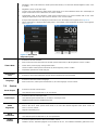
CONTROLLER Advance
F201A0500
General Information / Informazioni Generali / Informations Générales / Información General / Allgemeine Hinweise
Before using the unit, please read the following instruction manual carefully.
Prima dell’utilizzo dello strumento si raccomanda di leggere attentamente il seguente manuale operativo.
Avant d’utiliser l’instrument, il est recommandé de lire attentivement le présent manuel d’instructions.
Antes de utilizar el instrumento, le recomendamos que lea con atención el siguiente manual de funcionamiento.
Bitte lesen Sie vor Inbetriebnahme des Geräts diese Bedienungsanleitung sorgfältig durch
Do not dispose of this equipment as urban waste, in accordance with EEC directive 2002/96/CE.
Non smaltire l’apparecchiatura come rifiuto urbano, secondo quanto previsto dalla Direttiva 2002/96/CE.
Ne pas recycler l’appareil comme déchet solide urbain, conformément à la Directive 2002/96/CE.
No tirar el aparato en los desechos urbanos, como exige la Directiva 2002/96/CE.
Dieses Gerät unterliegt der Richtlinie 2002/96/EG und darf nicht mit dem normalen Hausmüll entsorgt werden.
This unit must be used for laboratory applications indoor only. The manufacturer declines all responsibility for any use of the unit that
does not comply with these instructions. If the product is used in a not specified way by the manufacturer or with not specified
accessories, product's safety may be compromised.
Questo strumento deve essere utilizzato solo per applicazioni di laboratorio per uso interno. La società produttrice declina ogni
responsabilità sull’impiego non conforme alle istruzioni degli strumenti. Se il prodotto viene utilizzato in un modo non specificato o con
accessori non specificati dal costruttore stesso, la sicurezza del prodotto potrebbe essere compromessa.
Cet instrument ne peut être utilisé pour les applications de laboratoire à l'intérieur seulement. Le fabriquant décline toute
responsabilité en cas d’utilisation non conforme aux instructions concernant ces instruments. Si le produit est utilisé d'une manière non
spécifiée par le fabricant ou accessoires non spécifiés, la sécurité du produit peut être compromise.
Este dispositivo sólo debe utilizarse para aplicaciones de laboratorio para uso interno.
El fabricante declina toda responsabilidad por el uso no conforme a las instrucciones de los dispositivos. Si se utiliza el producto de una
manera no especificada o con accesorios no especificados de el fabricante, la seguridad del producto puede estar comprometida.
Dieses Gerät muss nur für Laboranwendungen verwendet werden.Der Hersteller lehnt jede Haftung für unsachgemäße Verwendung
oder Nichtbeachtung dieser Bedienungsanleitung ab. Wenn das Produkt in einer Weise verwendet wird, die nicht vom Hersteller oder mit
unsachgemäßer Zubehör angegeben, kann das Produkt die Sicherheit beeinträchtigt werden.
This unit has been designed and manufactured in compliance with the following standards:
Lo strumento è stato progettato e costruito in accordo con le seguenti norme:
L’instrument a été conçu et fabriqué conformément aux normes suivantes:
El dispositivo se ha sido diseñado y fabricado de acuerdo con las siguientes normas:
Das Gerät wurde in Übereinstimmung mit folgenden Normen entwickelt und gebaut:
Safety requirements for electrical equipment for measurement, control and for laboratory use
Prescrizioni di sicurezza per apparecchi elettrici di misura, controllo e per l’utilizzo in laboratorio
Règles de sécurité pour appareils électriques de mesurage, de régulation et de laboratoire
Prescripciones de seguridad para equipos eléctricos de medición, control y su uso en laboratorio
Sicherheitsbestimmungen für elektrische Mess-, Steuer-, Regel- und Laborgeräte
IEC/EN 61010-1
Electrical equipment for laboratory use
UL 61010-1
General requirement - Canadian electrical code
CAN/CSA-C22.2 No.61010-1
VELP reserves the right to modify the characteristics of its products with the aim to constantly improving their quality.
Nell’impegno di migliorare costantemente la qualità dei prodotti, VELP si riserva la facoltà di variarne le caratteristiche.

2
Dans le but d’améliorer constamment la qualité de ses produits, VELP se réserve le droit d’apporter des modifications aux
caractéristiques de ceux-ci.
VELP se reserva el derecho de modificar las características de sus productos con el objetivo de mejorar constantemente su
calidad.
VELP behält sich zum Zwecke der ständigen Verbesserung der Produktqualität das Recht auf Änderung der
Geräteeigenschaften vor.
Safety Regulations / Norme di Sicurezza / Consignes de Securité / Advertencias de Seguridad / Sicherheitshinweise
The plug disconnects the instrument. Therefore, place the instrument where it can be quickly disconnected. / La spina è il mezzo di
disconnessione dell’apparecchio. Pertanto, non posizionare l’apparecchio in modo che sia difficile azionare il mezzo di disconnessione. /
Le bouchon est le moyen de déconnexion de l'appareil. Par conséquent, placer l'appareil où il peut être rapidement débranché. / El tapón
es el medio de desconexión del dispositivo. No coloque el dispositivo en una forma que es difícil de desconectar. / Der Stecker trennt das
Gerät. Daher Stellen Sie das Instrument, wo es schnell getrennt werden kann.
The values indicated on the rating plate of the instrument must correspond to those of the a.c. mains supply.
I valori di tensione indicato sulla targhetta del modello e quello di rete devono coincidere.
Les valeurs indiquées sur la plaque signalétique de l'appareil doivent correspondre à ceux de l'alimentation.
Los valores de tensión indicados en la placa y que de la red debe ser los mismos.
Die angegebene Spannung Wert auf dem Typenschild und das Netzwerk muss gleich sein.
Fasten the unit to the support rod (A00001300) using the fixing block (10007953). Position the instrument with a distance from the wall of 30
cm (at least).
Fissare saldamente lo strumento allo stativo (A00001300) mediante il blocchetto di fissaggio (10007953). Posizionare lo strumento ad una
distanza dalle pareti di almeno 30 cm.
Fixez l'unité à le statif (A00001300) con le noix de fixation double (A00001301) en utilisant le bloc de fixation (10007953). Positionner
l'appareil avec une distance de la paroi de 30 cm (au moins).
Asegurar firmemente la herramienta a la barra de soporte (A00001300) utilizando el bloque de fijación (10007953). Coloque la unidad con
una distancia de la pared de 30 cm (por lo menos)
Befestigen Sie das Gerät an der H-Stativ (A00001300) mit dem Befestigungsblock (10007953). Stellen Sie das Gerät auf einer ebenen
Fläche mit einem Abstand zur Wand von 30 cm (mindestens).
The unit is fitted with two fuses (2xT5 A L 250 V), found in the socket on the back. To replace one or more, disconnect the mains cable
and, using a screwdriver, lift up the small cover on the fuse box.
Lo strumento è dotato di due fusibili (2xT5 A L 250 V), annessi alla presa posta sul lato posteriore. Per la sostituzione, disconnettere il
cavo di alimentazione, e con un cacciavite fare leva nell’intaglio dello sportellino portafusibili.
L'appareil est équipé de deux fusibles (2xT5 A L 250 V), qui se trouvent dans la douille placée sur le dos. Pour remplacer, débranchez le
cordon d'alimentation et, à l'aide d'un tournevis, soulever le petit couvercle sur la boîte à fusibles.
El instrumento está equipado con dos fusibles (2xT5 A L 250 V), que se adjunta a la toma en la parte posterior. Para reemplazar, use un
destornillador para hacer palanca en la muesca de la tapa de la puerta.
Zwei Sicherungen (2xT5 A L 250 V (230V) ausgestattet sind, in die Buchse an der Rückseite positioniert werden . So ersetzen Sie eine
oder mehrere der Sicherungen entfernen Sie die Anschlussbuchse und mit einem Schraubendreher, heben Sie die kleine Abdeckung auf
dem Sicherungskasten.
The working speed set on the instrument must be such as to avoid wobbling and/or splashes.
Il numero di giri impostato deve escludere eventuali squilibri dell’agitatore e possibili spruzzi del prodotto agitato.
Le nombre de tours de l'ensemble agitateur doit exclure les déséquilibres et les éclaboussures du produit agité.
El número de revoluciones del agitador debe excluir cualquier desequilibrio y posible de salpicar de el producto agitado.
Die Arbeitsgeschwindigkeit des Gerätes muss gesetzt sein, wie Wackeln und / oder Spritzer zu vermeiden.
Do not use with explosive or dangerous materials for which the equipment is not designed. The stirrer must not be used in explosive
atmospheres, in bain-marie or to stir harmful liquids prior using protective measures according to the safety standards of the processed
products and/or in force in the laboratories including personal protective equipment and the presence of an extraction hood which ensures
at least 10-fold air change in accordance with the standards EN 14175 and DIN 12924.
Vietato l’uso con materiale esplosivo o pericoloso per cui l’apparecchio non è progettato. L’agitatore non può essere impiegato in
atmosfere esplosive, a bagno maria o per agitare liquidi pericolosi previo utilizzo di misure di protezione in accordo con le norme di
sicurezza dei prodotti in lavorazione e/o vigenti nei laboratori, compresi dispositivi di protezione individuale e la presenza di una cappa
aspirante che garantisca almeno 10 ricambi di aria in accordo con le norme EN 14175 e DIN 12924.
Ne pas utiliser avec des matières explosives et dangereuses pour lesquelles l'équipement n'est pas conçu. L'agitateur ne doit pas être
utilisé dans des atmosphères explosives, au bain-marie ou pour remuer des liquides nocifs avant l'utilisation de mesures de protection
selon les normes de sécurité des produits transformés et / ou en vigueur dans les laboratoires, y compris les équipements de protection
individuelle et la présence d'une extraction hotte assurant un renouvellement d'air d'au moins 10 fois conformément aux normes EN
14175 et DIN 12924.
No debe utilizarse con materiales explosivos y peligrosos para los que el equipo no está diseñado. El agitador no se debe usar en
atmósferas explosivas, en baño de maría o para agitar líquidos dañinos antes de usar medidas de protección de acuerdo con las normas
de seguridad de los productos procesados y / o vigentes en los laboratorios, incluido el equipo de protección personal y la presencia de
una extracción. Capucha que garantiza un cambio de aire de al menos 10 veces de acuerdo con las normas EN 14175 y DIN 12924.
Nicht mit explosivem Material zu verwenden, für die das Gerät nicht ausgelegt ist. Das Gerät kann nicht in explosionsgefährdeten
Bereichen eingesetzt werden, in einem Wasserbad oder zum Umrühren von schädlichen Flüssigkeiten verwendet werden, bevor
Schutzmaßnahmen gemäß den Sicherheitsnormen der verarbeiteten Produkte durchgeführt werden und / oder in den Laboratorien
einschließlich der persönlichen Schutzausrüstung und dem Vorhandensein einer Extraktion in Kraft sind Haube, die einen mindestens 10-
fachen Luftwechsel gemäß den Normen EN 14175 und DIN 12924 gewährleistet.

3
It is dangerous to run the motor free in air. Always fix the motor before turning the unit on.
Il funzionamento con motore libero in aria è pericoloso. Per ragioni di sicurezza fissare il motore prima di avviare lo strumento.
Il est dangereux de faire tourner le moteur à l'air libre. Fixez toujours le moteur avant d'allumer l'appareil.
Es peligroso hacer funcionar el motor con aire libre. Siempre arregle el motor antes de encender la unidad.
Es ist gefährlich, den Motor mit freier Luft laufen zu lassen. Befestigen Sie den Motor immer, bevor Sie das Gerät einschalten.
The solution may release toxic, dangerous or poisonous gases. Adequate safety measures must be taken, in accordance with the safety
regulations in force, including the presence of hood and personal protective equipment (masks, gloves, goggles, etc.).
Le sostanze potrebbero emanare gas tossici e/o pericolosi e/o velenosi. Adeguate misure di sicurezza devono essere prese, in accordo
con le normative di sicurezza dei prodotti in lavorazione e/o vigenti nei laboratori, compresa la presenza di cappe aspiranti e mezzi di
protezione individuale (maschere, guanti, occhiali, camici, ecc.).
La solution peut libérer gaz toxiques ou dangereux. Des mesures de sécurité adéquates doivent être prises, en conformité avec les
règlements de sécurité en vigueur, compris la présence de la hotte de laboratoire et équipements de protection individuelle (masques,
gants, lunettes, etc.).
Las sustancias pueden emitir tóxicos o peligrosos gas. Medidas de seguridad adecuadas deben ser adoptadas, de acuerdo con las
normas de seguridad vigentes en los laboratorios, incluyendo la presencia de la campana de humos y el equipo de protección personal
(mascarillas, guantes, gafas, etc.)
Die erwärmte Lösung kann giftige oder gefährliche Gase freigeben. Angemessene Sicherheitsmaßnahmen zu treffen, werden in
Übereinstimmung mit den geltenden Sicherheitsvorschriften, einschließlich der Anwesenheit Dunstabzug und persönliche
Schutzausrüstungen (Masken, Handschuhe, Schutzbrille, etc.).
The instrument contains a battery. Its substitution must be carried out by authorized Velp personnel only.
Lo strumento contiene una batteria. La sua sostituzione dovrà essere eseguita da parte di personale autorizzato Velp.
L'instrument contient une batterie. Son remplacement doit être effectué uniquement par du personnel autorisé de Velp.
El instrumento contiene una batería. Su sustitución debe ser realizada únicamente por personal autorizado de Velp.
Das Instrument enthält eine Batterie. Der Ersatz darf nur von autorisiertem Velp-Personal durchgeführt werden.
Contains FCC ID : YOPGS2101M / Contiene FCC ID: YOPGS2101M / Contient FCC ID: YOPGS2101M / Contiene FCC ID:
YOPGS2101M / Es enthält FCC ID : YOPGS2101M

4
Contents / Indice
1. INTRODUCTION .............................................................................................................................................................. 5
2. ASSEMBLY AND INSTALLATION ................................................................................................................................... 6
3. DISPLAY SYMBOLS ........................................................................................................................................................ 7
4. WORKING ........................................................................................................................................................................ 8
5. EXTERNAL CONNECTIONS ........................................................................................................................................... 9
6. VELP ERMES CONFIGURATION ................................................................................................................................. 10
7. MENU ............................................................................................................................................................................. 11
7.1 MENU STRUCTURE .................................................................................................................................................................. 11
7.2 METHODS .............................................................................................................................................................................. 12
7.2.1 Method set-up .................................................................................................................................................................... 13
7.3 GRAPH .................................................................................................................................................................................. 15
7.4 SAFETY .................................................................................................................................................................................. 15
7.5 SET-UP .................................................................................................................................................................................. 16
7.6 SERVICE ................................................................................................................................................................................. 17
8. ERROR MESSAGES ..................................................................................................................................................... 18
9. MAINTENANCE ............................................................................................................................................................. 18
10. TECHNICAL DATA ........................................................................................................................................................ 18
11. ACCESSORIES ............................................................................................................................................................. 19
12. MOTOR INFORMATION ................................................................................................................................................ 19
1. INTRODUZIONE ............................................................................................................................................................ 20
2. MONTAGGIO E INSTALLAZIONE ................................................................................................................................ 20
3. SIMBOLI DISPLAY ......................................................................................................................................................... 21
4. CONTROLLI DI FUNZIONAMENTO .............................................................................................................................. 22
5. CONNESSIONI ESTERNE ............................................................................................................................................ 23
6. CONFIGURAZIONE VELP ERMES ............................................................................................................................... 24
7. MENÙ ............................................................................................................................................................................. 25
7.1 STRUTTURA DEL MENÙ ............................................................................................................................................................. 25
7.2 METODI ................................................................................................................................................................................ 26
7.2.1 Impostazione metodo ........................................................................................................................................................ 27
7.3 GRAFICO ................................................................................................................................................................................ 29
7.4 SICUREZZA ............................................................................................................................................................................. 29
7.5 IMPOSTAZIONI ........................................................................................................................................................................ 30
7.6 SERVICE ................................................................................................................................................................................. 31
8. MESSAGGI DI ERRORE ............................................................................................................................................... 32
9. MANUTENZIONE E PULIZIA ........................................................................................................................................ 32
10. CARATTERISTICHE TECNICHE .................................................................................................................................. 32
11. ACCESSORI .................................................................................................................................................................. 33
12. INFORMAZIONI MOTORI .............................................................................................................................................. 33
13. WIRING DIAGRAM / SCHEMA ELETTRICO / SCHEMA ELECTRIQUE / ESQUEMA ELÉCTRICO / SCHALTPLAN 34
14. DECLARATION OF CONFORMITY / DICHIARAZIONE DI CONFORMITA / DECLARATION DE CONFORMITE /
DECLARACIÓN DE CONFORMIDAD / KONFORMITÄTSERKLÄRUNG ........................................................... 35

5
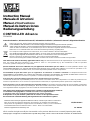
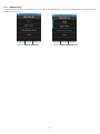
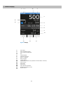
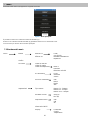
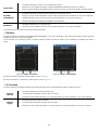
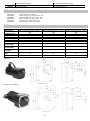
1. Introduction
CONTROLLER Advance is an innovative solution for control and data logging in process reactors. It is able to monitor the temperature
in the reactor and the shaft rotation speed of brushless gear-motors for liquid volumes until 100L, even with viscosity changes. The motor
is reversible.
All data logging features can be managed through VELP Ermes platform or USB by a PC.
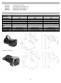
*Circular connectors Model MIL-C-505 MS3102A-14S-6
**Circular connectors Model MIL-C-505 MS3102A -14S-2
A
Display LCD
B
Display keys
C
Speed control knob
D
Lock key
E
Main switch
F
Motor circular connector 6P *
G
Motor circular connector 4P **
H
USB door
I
Appliance inlet with fuse holder
J
Pt100 socket
EN
Figure 1. OHS 100 Advance
A
B
Figure 1. CONTROLLER Advance
C
E
D
F
G
I
J
H

6
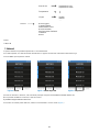
2. Assembly and installation
• Unpacking
➢ Check the integrity of the unit after unpacking.
• The box includes
➢ CONTROLLER Advance
➢ Power supply cable
➢ Instruction manual
• First installation
➢ Place the unit on non-flammable surface
➢ Fix the instrument to the support through the handle
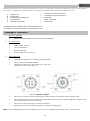
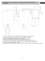
➢ Connect the instrument to one of the following brushless motors 4 poles, 24 V:
1/4HP, Max 8,3 A or 1/11HP, Max 4.4 A
Figure 2. Connector side view
➢ Make sure that the rating value of the instrument corresponds to the one of the power supplies.
➢ Ensure that the socket provided, with grounding, is compliant with the current safety norms and easy to reach. Use only
the cable provided with the instrument.
➢ Insert the power cable into the socket and switch the instrument on.
➢ Select the motor type in the SET UP/Motor type menu.
NOTE: the cable can be substituted only by main cables with same features (T=70°C, connector C14).

7
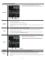
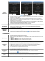
3. Display symbols
1
Wi-Fi symbol
2
Start Mode symbol
3
Vibration Sensor symbol
4
Hour
5
Current Speed
6
Set Speed
7
Timer or Time counter
8
Set Timer
9
Current Torque
10
Current temperature (only when Pt100 probe is connected)
11
Reverse button
12
Timer button
13
Menu button
14
Current rotation direction
15
Current Method indication
16
Motor type
5
6
7
1 2 3 16 4
8
9
10
13 12 11
14
15
Figure 3. Display
M5:1-500

8
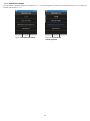
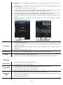
4. Working
Commissioning
➢ Switch on the instrument using the main switch (E)
➢ Display (A) shows Welcome page and the main screen
Stirring
➢ Adjust speed set point by turning the speed control knob (C). As soon as the knob is moved, set rpm (6)
becomes blue.
➢ Click the speed control knob (C) to start stirring.
➢ Speed increases until set point is achieved.
➢ A microprocessor ensures constant speed even when the viscosity changes (counter-reaction).
➢ Switch off the stirring by clicking the knob (C).
Timer
➢ Click Timer button (12) to select the timer.
➢ Set timer (8) - time becomes blue. Adjust timer by turning the speed control knob (C).
➢ Click the knob (C) to confirm.
➢ If the instrument is already working, timer countdown starts immediately, otherwise timer (7) is fixed as set
timer (8) until stirring begins.
➢ If timer is not set, set timer (8) shows hh:mm:ss and timer (7) works as a counter.
CW / CCW
➢ Set the rotating direction by clicking CW/CCW button (11) and
rotating the speed control knob (C).
➢ Click the knob (C) to confirm clockwise (CW) or counterclockwise
(CCW) direction. Once confirmed, “CW/CCW” symbol becomes
black.
Torque
➢ The intensity of the torque is indicated on the main screen (9).
Lock
➢ Holding the Lock key (D) for 3 seconds, the instrument will lock its settings during operations.
➢ Unlock the control panel by holding the Lock key (D) for 3 seconds.
➢ If other buttons are clicked while the instrument is locked, the two LEDs aside lock button blink for many
seconds.
Figure 4. Main screen
Figure 5. Set Rotation Direction

9
5. External Connections
USB
➢ This model has USB connection in the back for PC controlling, data logging and software upgrading by PC.
➢ Software version, dedicated program to be installed in the PC, and software installation guide have to be
requested by e-mail to [email protected]
Pt100
➢ This model has Pt100 connection in the back for fluid temperature measurement (measuring range from
-200°C to + 550°C).
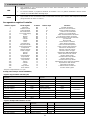
Controller register assignment
Register address
Register name
Write
Byte Number
Function/expanation
1
Instrument
NO
2
Instrument model
2
Serial number
NO
6
Instrument serial number
5
Product code
NO
12
Instrument product code
11
Main board sw
NO
8
Main board sw version
15
Display board sw
NO
8
Display board sw version
24
State
NO
2
Instrument state
25
Alarm
NO
2
The instrument notifies an alarm
26
Gear
NO
2
Gear set (only for OHS200)
27
Speed
NO
2
rpm measured
28
Torque
NO
2
Ncm measured
29
Timer
NO
4
Residual timer or counter
31
Timer set point
NO
4
Timer set value
33
Speed set point
NO
2
Speed set value
48
Pt100 connection
NO
2
Pt100 connected to the instrument
49
Temperature
NO
2
Temperature indication
50
Speed limit
NO
2
Speed maximum value
51
Torque limit
NO
2
Torque maximum value
52
Ramp
NO
2
Setting of acceleration
53
Method
NO
2
Reading of method number
54
Method n steps
NO
2
Total number of steps
55
Method step
NO
2
Current step visualized
56
Method n loops
NO
2
Total number of loops
57
Method loop
NO
2
Current loop visualized
102
Gear
SI
2
Setting of gear (only for OHS200)
103
Speed
SI
2
Setting of the speed
104
Timer
SI
4
Setting of the timer
106
Motor stop
SI
2
Motor stops stirring
107
Motor start
SI
2
Motor starts stirring
Sampling time: 1s or more
Examples (CRC 16 bit for standard MODBUS)
Reading single register: Speed (rpm)
Request
Reply
Field
(Hex)
Field
(Hex)
Description
Address
0x64
Address
0x64
Control command
0x03
Control command
0x03
High start address
0x00
Number of bytes
0x02
Low start address
0x1B
High register value
0x01
340 (RPM)
Number of High registers
0x00
Low register value
0x54
Number of Low registers
0x01
High CRC
0xF4
High CRC
0xFD
Low CRC
0x23
Low CRC
0xF8
Reading multiple register: Serial number
Request
Reply
Field
(Hex)
Field
(Hex)
Description
Address
0x64
Address
0x64
Control command
0x03
Control command
0x03
High start address
0x00
Number of bytes
0x06
Low start address
0x02
High register value
0x31
12345

10
Number of High registers
0x00
Low register value
0x00
Number of Low registers
0x03
High register value
0x33
High CRC
0xAD
Low register value
0x32
0x00 0x31 0x32 0x33 0x34 0x35
Low CRC
0xFE
High register value
0x35
Low register value
0x34
High CRC
0x0A
Low CRC
0x0A
Writing single register: STOP rotation
Request
Field
(Hex)
Description
Address
0x64
Control command
0x06
High start address
0x00
Low start address
0x6A
High register value
0x00
Stop rotation
Low register value
0x01
High CRC
0x61
Low CRC
0xE3
Virtual serial port
Baudrate
9600
Bits
8
Stop Bit
1
Parity
None
Maximum number of
registers for single request
24
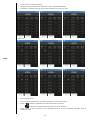
6. VELP Ermes Configuration
VELP Ermes is a revolutionary cloud platform that transforms and improves your laboratory experience by creating an ecosystem of
instruments, people and data. The VELP Ermes Cloud Platform is able to reduce distances and accelerate scientific processes in total
safety. In order to access on Ermes, you need to enable your VELP account by selecting "Configure your VELP Ermes account" at
http://www.velp.com/en/login.
To be able to communicate, the instrument needs to be in the operating range of laboratory Wi-Fi (2.4 GHz) and be configured as follows:
➢ Switch on the CONTROLLER Advance and select AP in the menu Set-up Wi-Fi (see chapter 7.5).
➢ Using the PC/Tablet/Mobile phone, select the RC_SERIAL NUMBER available on the Wi-Fi list, in order to connect directly to the
instrument.
➢ Open a browser on the PC/Tablet/Mobile phone and insert the address 192.168.240.1 to reach the configuration page. Insert
“admin” “admin” when requested as user name and password.
➢ Set the parameters required to connect to your Wi-Fi (network name, password, security, mac address, etc.) according to your
internal procedure and save. If necessary, contact your IT administrator.
➢ Select menu Ermes from the Service menu (see chapter 7.6) and proceed with the product registration from the VELP Ermes Cloud
Platform. For more information see FAQ on VELP website.
NOTE: To access to VELP Ermes it is necessary to have a VELP account.

11
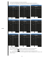
7. Menu
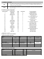
Clicking Menu button (13) the following figure appears
It’s possible to move among submenus rotating the speed control knob (C).
Enter in a submenu with a single click of the speed control knob (C) once it’s highlighted in blue.
Press Home to go back to the main screen.
7.1 Menu Structure
Menu
Methods
Method 01
Steps
…
Start time
Method 10
Intermittent mode
Loop
Graph
Safety
Speed Limit
Torque Limit
Temperature Limit
Delta T
Interval time
Speed reduction
Acceleration
Slow
Standard
Fast
Vibration Sensor
OFF
Low
Medium
High
Set-up
Motor Type
Motor 5:1 – 500rpm
Motor 6:1 – 417 rpm
Motor 10:1 – 250rpm
Start Mode
Stop (A)
Run (B)
Wi-Fi Set-up
OFF
ON
AP
Wi-Fi Information
Display
Brightness
Figure 6. Main Menu

12
7.2 Methods
In this submenu it is possible to set 10 different methods.
Once set, a method becomes white in the method list and a blue bar appears on the left.
Press START to begin the method.
When a Method is working, on the main screen the current method (15) is shown.
It’s not possible to modify speed, gear, or the timer.
It’s possible to navigate in menu.
To stop a method before its end, enter in the method list and click STOP (Figure ).
Torque
Temperature
Time & Date
Set Time
Set Date
Temperature Unit
°C
°F
Language
English
Italiano
….
Service
Reset Torque
Real Torque
Pt100 Alignment
Reset Parameters
Update Software
Counter
Ermes
Timer
CW/CCW
Figure 7. Methods
Figure 8. Methods set
Figure 9. Stop Method


14
Steps
➢ 5 steps can be set for each method.
➢ All steps are programmable with speed, timer, ramp, and intermittent mode.
➢ A Method is considered set when at least speed and timer are set for one step.
Figure 12
➢ Rpm: set point speed
➢ Time: countdown performed for each step visualized also on the main screen
➢ Ramp: if is selected, Controller stirs for all the time at the speed set
if is selected, Controller reaches the speed set in time selected
➢ Interm. Mode: if YES is selected, but no intermittent mode is set for the method, Controller works in
continuous mode.

15
Start Time
➢ It allows to set an hour at which the method starts.
➢ Enter in the menu, rotate speed control knob (C) till the desired hour. Click the knob to confirm.
➢ Even if a Start Time is set, the method begins if START button in method list is clicked.
Intermittent
Mode
➢ It allows to set stirring period and stop period alternatively.
➢ Enter in the menu, rotate speed control knob (C) till the desired working time. Click to confirm.
➢ Rotate speed control knob (C) till the desired pause time. Click to confirm.
➢ Click again the knob to modify set values.
Loop
➢ It allows to repeat the whole method N times.
➢ Enter in the menu, rotate speed control knob (C) till the desired value. Click to confirm.
Click RESET to erase all method values.
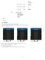
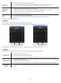
7.3 Graph
In this submenu is possible to visualize the graph of the current analysis.
Click RESET to erase the graph. Only the last 60 minutes are shown. Click ZOOM to see the last 3 minutes.
When a method is set graph appears as in Figure 13. When a method is not set, graph appears as in Figure 14.
7.4 Safety
In this submenu it’s possible to set all limits linked to the safety depending on the working conditions
Speed Limit
➢ It allows to set the speed full scale.
➢ The maximum speed value is set by default.
➢ Enter in the menu, rotate speed control knob (C) by 100 rpm steps till the desired value. Click to confirm.
Torque Limit
➢ It allows to set the torque limit.
➢ The maximum value is set by default.
➢ Enter in the menu, rotate speed control knob (C) by 10 Ncm steps till the desired value. Click to confirm.
Temperature
Limit
➢ It allows to set a speed reduction if Pt100 detects a certain temperature increase (or decrease) in a defined
time.
Figure 13. Graph with method
Figure 14. Graph without method

16
Figure 15. Temperature Limit
➢ Enter in the menu, rotate speed control knob (C) till the delta temperature desired value. Click to confirm.
➢ Rotate the knob (C) to set the interval time in which the delta temperature has to be considered. Click to
confirm.
➢ Rotate the knob (C) to set the percentage of speed reduction desired if the selected delta temperature is
detected in the set interval time. Click to confirm.
➢ Speed reduction can be set by 10% steps.
Acceleration
➢ It allows to choose among 3 different acceleration types when the instrument starts to stir or when a higher
set point value is set.
➢ Enter in the menu, select Slow, Medium, or Fast depending on the customer application.
➢ Click speed control knob (C) to confirm.
Vibration
sensor
➢ It allows to set a vibration sensitivity level.
➢ Enter in the menu, rotate speed control knob (C) to select OFF, Low, Medium or High. Click to confirm.
➢ When vibration sensor level is set different than OFF, appears on the blue upper bar (3).
7.5 Set-up
Motor Type
➢ It allows to set the type of the motor connected to the instrument
➢ Enter in the menu, rotate speed control knob (C) to select the motor connected physically. Click to confirm.
➢ Motor 5:1 – 500 rpm: 4 poles, 24V, 1/4HP, Max 8.3A, Max rpm 500
➢ Motor 6:1 – 417 rpm: 4 poles, 24V, 1/11HP, Max 4.4A, Max rpm 417
➢ Motor 10:1 – 250 rpm: 4 poles, 24V, 1/4HP, Max 8.3A, Max rpm 250
Start Mode
➢ It allows to set instrument’s restart mode in case of blackout or power loss.
➢ Enter in the menu, rotate speed control knob (C) to select Stop or Run. Click to confirm.
➢ Stop: when the instrument is switched on, it’s requested a click of the control knob to start stirring.
➢ Run: when the instrument is switched on, it restarts to work with the last set point set.
➢ If Stop is selected, A appears on the blue upper bar (2).
➢ If Run is selected, B appears on the blue upper bar (2).
Wi-Fi Set-up
➢ It allows to switch on wi-fi module for IoT transmission.
➢ Enter in the menu, rotate speed control knob (C) to select ON or OFF. Click to confirm.
➢ When wi-fi is ON, appears on the blue upper bar (1).
Wi-Fi
Information
➢ It describes all wi-fi information (MAC address, Power of signal, wi-fi name).
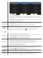
Display
➢ It allows for brightness to be set or if torque and temperature should be displayed on the main screen.
➢ Enter in the menu and scroll with speed control knob (C). Click to enter in submenus.

17
➢ Brightness: enter in this submenu, rotate speed control knob (C) to select the desired brightness value. Click
to confirm.
➢ Brightness can be set by 10% steps.
➢ Torque: enter in this submenu, rotate speed control knob (C) to choose between ON or OFF if the display of
torque on the main screen is desired or not. Click to confirm.
➢ Temperature: enter in this submenu, rotate speed control knob (C) to choose between ON or OFF if the
display of temperature on the main screen is desired or not. Click to confirm
➢ If torque and temperature are displayed on the main screen, the display menu appears as in Figure 16.
➢ When temperature is displayed but Pt100 probe is not inserted in the instrument, the main screen appears
as in Figure 17.
Time & Date
➢ It allows to set hour and date.
➢ Enter in the menu and select Set Time. Rotate speed control knob (C) till the right time. Click to confirm.
➢ Return to the previous page clicking BACK button.
➢ Select Set Date. Rotate speed control knob (C) till the right day. Click to confirm
➢ Repeat the operation for month and year.
Temperature
Unit
➢ It allows to choose the temperature and the torque unit that have to be visualized
Language
➢ It allows to select the interface language.
➢ Enter in the menu, rotate speed control knob (C) to select language. Click to confirm.
7.6 Service
Reset Torque
➢ It allows to reset the current torque.
➢ Click with the speed control knob (C) to reset torque.
Real Torque
➢ It allows to return to real torque value.
➢ Click with the speed control knob (C) to return to real torque value.
➢ Negative torques can’t be visualized anymore.
Pt100
Alignment
➢ It allows for the alignment of the Pt100 probe to a reference thermometer.
➢ Enter in the menu, rotate speed control knob (C) to select the desired alignment value (from -10.0°C to
10.0°C). Click to confirm.
➢ Alignment sensitivity 0.1°C.
Reset
Parameters
➢ It allows to return to default value for all functions.
➢ Click with the speed control knob (C) to reset parameters.
Update
Software
➢ It allows to update the device with a new software version.
➢ Software version, dedicated program to be installed in the PC, and software installation guide have to be
Figure 16. Torque and
temperature shown
Figure 17. Main without
temperature probe

18
requested by e-mail to [email protected].
Counter
➢ It allows to see the number of instrument working hours.
Ermes
➢ It allows to connect the instrument to Ermes Cloud.
8. Error messages
When the display shows an error message, the stirring function stops automatically.
Error code
Cause
AL1
Motor doesn’t start stirring
AL2
High internal motor temperature
AL3
Motor overload
AL4
High driver temperature
AL5
Safety relay fault
AL10
Vibrations too high
AL11
Temperature too high (only with Pt100 inserted)
AL12
Temperature too low (only with Pt100 inserted)
To remove the error message, disconnect the instrument from the power supply.
If alarm persists on the display, please contact VELP Scientifica technical service department. [email protected]
9. Maintenance
10. Technical data
Model
F201A0500
General
features
Power supply
115-230V (+/-10%) – 50-60 Hz
Dimensions (WxHxD)
75x150x190 mm
(2.95x5.90x7.48 in)
Weight
2,5 kg (5,51 lb)
Power input
300 W
Construction material (structure)
Stainless steel
Working in continuous
Admitted
Settable restart modality
Stop or work
Noisiness
<< 60 dBa
Environmental temperature admitted
+5…+40 °C
Storage temperature admitted
-10…+60 °C
Max humidity
80%
Overvoltage category
II
Pollution degree CEI EN61010-1
2
Max altitude
2000 m
Stirring
Programmable speed range
35-500rpm * depends to the motor
Speed selection
1 rpm step
Rpm accuracy
± 1
Stirring alarm
Motor fault
Torque
Max torque admitted
280 Ncm (8,3 A)
Counters
Board counter
Working hours
Maintenance
➢ No routine or extraordinary maintenance is necessary;
➢ Repairs must be carried out by authorized Velp personnel only;
➢ Instrument must be transported in its original packaging any indications present on the original packaging
must be followed (e.g., palletized);
Cleaning
➢ Disconnect the unit from the power supply and use a cloth dampened with a non-flammable non-
aggressive detergent.

19
11. Accessories
A00000394 Pt100 probe XL Ø6 500mm
A00000415 Motor 10 lb*in, 417 rpm, 1/11 HP -24V
A00000416 Motor 28 lb*in, 500 rpm, 1/4 HP -24V
A00000417 Motor 55 lb*in, 250 rpm, 1/4 HP -24V
E00010012 VELP Ermes 1 year Connection
E00010036 VELP Ermes 3 years Connection
12. Motor information
Code
A00000415
A00000416
A00000417
Description
Motore 10 lb*in, 417 rpm, 1/11 HP
-24V
Motore 28 lb*in, 500 rpm, 1/4 HP -
24V
Motore 55 lb*in, 250 rpm, 1/4 HP -
24V
Torque [N*cm]
113
316
621
Torque [lb*in]
10
28
55
Speed [rpm]
417
500
250
Power supply [V]
24
24
24
Power [W]
68
187
187
Power [HP]
1/11
1/4
1/4
Shaft diameter
[mm]
11
19
19
Shaft lenght [mm]
31,4
42,4
42,4
Fixing informations
Datasheet below
Datasheet below
Datasheet below
Cables lenght [m]
1,5
1,5
1,5
Reactor Volume
Up to 25 liters of water
Up to 50 liters of water
Up to 100 liters of water
A00000415:
A00000416 – A00000417

20
1. Introduzione
CONTROLLER Advance è la soluzione innovativa per il controllo e la registrazione dei dati nei reattori di processo per volumi di liquidi
fino a 100L. La registrazione dei dati può essere gestita tramite la piattaforma VELP Ermes oppure tramite USB via PC.
*Connettore circolare Modello MIL-C-505 MS3102A-14S-6
**Connettore circolare Modello MIL-C-505 MS3102A -14S-2
2. Montaggio e installazione
• Rimozione dall’imballo
➢ Controllare l’integrità dello strumento dopo aver rimosso l’imballo
• La scatola include
➢ CONTROLLER Advance
➢ Cavo di alimentazione
➢ Manuale di istruzioni
➢ Sonda Pt100 Ø 3mm con cavo 1m
• Prima installazione
➢ Posizionare lo strumento su una superficie non infiammabile
➢ Fissare lo strumento all’asta di sostegno
➢ Collegare lo strumento a uno dei seguenti motori 4 poli, 24 V:
1/4HP, Max 8,3 A o 1/11HP, Max 4.4 A
Figura 1. Vista lato connettori
➢ Assicurarsi che il valore di tensione di alimentazione dello strumento corrisponda al valore di tensione di rete
➢ Assicurarsi che la presa di corrente fornita sia conforme alle norme di sicurezza e facile da raggiungere. Utilizzare solo il
cavo di alimentazione fornito con lo strumento
➢ Inserire il cavo nella presa di rete e accendere lo strumento
➢ Selezione il tipo di motore fisicamente collegato, nel menù SET UP/Motor type
NOTA: il cavo di alimentazione può essere sostituito solo con un cavo con caratteristiche equivalenti (T=70°C, connettore C14).
F
Connettore circolare motore 6P *
G
Connettore circolare motore 4P **
H
Porta USB
I
Presa a vaschetta
J
Presa Pt100
A
Display LCD
B
Tasti display
C
Encoder velocità agitazione
D
Tasto di blocco
E
Interruttore principale
IT
La pagina si sta caricando...
La pagina si sta caricando...
La pagina si sta caricando...
La pagina si sta caricando...
La pagina si sta caricando...
La pagina si sta caricando...
La pagina si sta caricando...
La pagina si sta caricando...
La pagina si sta caricando...
La pagina si sta caricando...
La pagina si sta caricando...
La pagina si sta caricando...
La pagina si sta caricando...
La pagina si sta caricando...
La pagina si sta caricando...
La pagina si sta caricando...
-
 1
1
-
 2
2
-
 3
3
-
 4
4
-
 5
5
-
 6
6
-
 7
7
-
 8
8
-
 9
9
-
 10
10
-
 11
11
-
 12
12
-
 13
13
-
 14
14
-
 15
15
-
 16
16
-
 17
17
-
 18
18
-
 19
19
-
 20
20
-
 21
21
-
 22
22
-
 23
23
-
 24
24
-
 25
25
-
 26
26
-
 27
27
-
 28
28
-
 29
29
-
 30
30
-
 31
31
-
 32
32
-
 33
33
-
 34
34
-
 35
35
-
 36
36


Velp Scientifica CONTROLLER Advance Manuale utente
- Tipo
- Manuale utente
in altre lingue
Documenti correlati
-
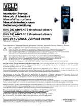 Velp Scientifica OHS Advanvce Manuale utente
-
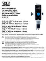 Velp Scientifica OHS Digital Manuale utente
-
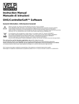 Velp Scientifica OHS/ControllerSoft Manuale utente
-
Chemglass CG-1995-20 Manuale del proprietario
-
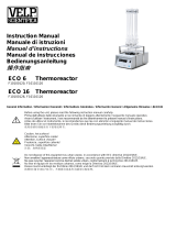 Velp Scientifica ECO 16 Manuale utente
-
 Velp Scientifica BOD Sensor Manuale utente
-
 Velp Scientifica AREX-6 CONNECT PRO Manuale del proprietario
-
 Velp Scientifica RESPIROMETRIC Sensor Manuale utente
-
 Velp Scientifica DLS DLH Manuale utente


Altri documenti
-
 VELP Scientific VSI-SB20500410 Manuale del proprietario
-
 VELP Scientific SB20510061 Manuale del proprietario
-
 VELP Scientific F20500051 Manuale del proprietario
-
 VELP Scientific F20500011 Manuale del proprietario
-
 VELP Scientific F20500101 Manuale del proprietario
-
VELP Scientific SA20500413 Manuale del proprietario
-
Chemglass CG-1995-V-22 Manuale del proprietario


