Pottinger Control console PC3.0 LW Istruzioni per l'uso
- Tipo
- Istruzioni per l'uso

EN Manual for Operator Terminal
Power Control 3.0
Pöttinger Material Nr.: 487.760, 487.779, 487.793
V1.1
Changes
Version
Change
Date
Sign
V1.0
First Version
20.01.2021
bumbrai
V1.1
New System-Menu navigation,
add input field UT instance
add input field summer/wintertime, 12h/24h Mode
N
11.02.2022
bumbrai
Approved:
Created:
Date 06.11.2018
Sign Bumberger
Checked:
Date
Sign
Approved:
Date
Sign

Manual for Operator Terminal
Power Control 3.0
25.03.2022 Rainer Bumberger 487.760 Manual Power Control 3.0 -
V1.1_en.docx 2 / 19
content
1 Therms and abbrevations ..................................................................................................... 3
2 Hardware deskription............................................................................................................. 3
2.1 Operation Voltage capability: ......................................................................................... 3
2.2 TFT Display: ................................................................................................................... 3
2.3 Front foil: ........................................................................................................................ 3
2.4 Buzzer: ........................................................................................................................... 3
2.5 RTC: ............................................................................................................................... 3
3 User Interface ......................................................................................................................... 4
3.1 Hardkey Button behaviour ............................................................................................. 4
3.2 System Menu ................................................................................................................. 5
3.3 TECU Menu ................................................................................................................... 5
3.3.1 Base Settings ....................................................................................................... 5
3.3.2 WBS Wheel Based Speed ................................................................................... 6
3.3.3 GBS Ground Based Speed ................................................................................. 7
3.3.4 100m calibration for wheel and ground based speed .......................................... 7
3.3.5 PTO and Hitch settings ........................................................................................ 8
3.4 System Settings ............................................................................................................. 9
3.4.1 Touch calibration ............................................................................................... 11
3.4.2 Delete IOP Objectpool ....................................................................................... 12
3.4.3 IOP Objectpool Download ................................................................................. 12
4 Electrical connectivity ......................................................................................................... 14
4.1 Pinout ........................................................................................................................... 14
4.2 Main Connector ............................................................................................................ 15
5 TECU Tractor ECU ................................................................................................................ 16
5.1 Tractor side pin allocation ............................................................................................ 16
5.1.1 7-pole in-Cab signal connector ISO 11786........................................................ 16
5.2 Terminal side pin allocation ......................................................................................... 17
5.2.1 Tractor speed Input: 2 inputs ISO11786:1995 compliant : ................................ 17
5.2.2 Rear PTO speed Input: 1input ISO11786:1995 (chapter 5.3) compliant: ......... 17
5.2.3 Three-point Digital Input: 1input ISO11786:1995 (chpt. 5.4) compliant : .......... 18
5.2.4 Three-point analog Input: 1input ISO11786:1995 chapter 5.5 compliant : ........ 18
5.2.5 Ignition In/Output: 1 channel In/output ............................................................... 18
5.3 EMC ............................................................................................................................. 19
5.3.1 EN ISO 14982:2009 ........................................................................................... 19
5.4 ESD .............................................................................................................................. 19
5.4.1 EN ISO 10605 .................................................................................................... 19

Manual for Operator Terminal
Power Control 3.0
25.03.2022 Rainer Bumberger 487.760 Manual Power Control 3.0 -
V1.1_en.docx 3 / 19
1 Therms and abbrevations
Therm Meaning
ECU
Electronic control unit
Nd
not defined
tbd
to be defined
2 Hardware deskription
2.1 Operation Voltage capability:
Typical 12V DC (from tractor)
- Preferred: 8 .. 28V DC
- Minimum: 8 ..18V DC,
2.2 TFT Display:
Size: 5”, built in landscape direction
o Resolution: 800 x 480 dot matrix
o Colors: 64k
o Backlight LED
2.3 Front foil:
Keyboard backlight dimming, controlled by 8 steps
UV resistant front foil material
2.4 Buzzer:
o built into rear side,
o 60dB @30cm distance (Angel <=10° from center)
o Fix frequency of the buzzer, (rated frequency: 4.25kHz).
o Volume controlled by 16 steps. Fine loudness control is not possible because of the internal oscillator.
The reduced volume depends on the ambient temperature, too.
o IP65 sealed by the case, the component (buzzer) is not IP protected.
2.5 RTC:
Real time clock with removable/ exchangeable Lithium battery: Battery CR2032
o typical lifetime of the battery: 10 years from production (depends on the ambient temperature)
o replace by opening of the screwed housing.

Manual for Operator Terminal
Power Control 3.0
25.03.2022 Rainer Bumberger 487.760 Manual Power Control 3.0 -
V1.1_en.docx 4 / 19
3 User Interface
3.1 Hardkey Button behaviour
- Power ON/Off: press 1 sec for switch ON/OFF
- House Button: Jump Back to System start menu
- ISB: ISOBUS shortcut button: Stop all ISOBUS functions
ISO11783 ISB function support
- 16 Hardkeys: The printing belongs to the machine function (e.g. baler, seeder, loader wagon,
mower,…)

Manual for Operator Terminal
Power Control 3.0
25.03.2022 Rainer Bumberger 487.760 Manual Power Control 3.0 -
V1.1_en.docx 5 / 19
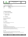
3.2 System Menu
Buttons:
• No ECU If a machine is connected: go to machine view
• TECU Go to TECU functions
• Settings Terminal specific settings
Information view:
• Serial Number
• Hardware Version
• EDC Version
• Software Version
3.3 TECU Menu
3.3.1 Base Settings
TECU enable Enable/Disable the TECU functions. (restart of the terminal needed)
If the terminal is connected to a ISOBUS tractor, the TECU has to be disabled! Here the
TECU information’s shall come from the tractor.

Manual for Operator Terminal
Power Control 3.0
25.03.2022 Rainer Bumberger 487.760 Manual Power Control 3.0 -
V1.1_en.docx 6 / 19
Wide Hysteresis: Needed for some tractor interfaces, if they have different signal levels.
Default is ON. If the TECU won’t work properly, change to OFF.
Buttons:
House Go to Start Menu
Wheel Speed Go to settings of the Wheel Speed
Ground Speed Go to settings of the Ground Speed
PTO Hitch Go to settings of the PTO and Hitch
3.3.2 WBS Wheel Based Speed
Mainly this signal is generated in the gearbox of the tractor. This is the theoretical speed of the tractor,
because the slip of the wheels is not measured here. Higher accuracy is available with the GBS Ground
Based Speed
Speed: measured wheel speed
Distance measured wheel distance. Can be reset with the button ‘RESET COUNTER’
Pulse/100m Number of Pulses over a distance of 100m.
Default 13.000 Pulses
If the accuracy of the speed signal is not valid to the real speed,
a 100m calibration has to be initiated,
see 100m calibration for wheel and ground based speed
Pulse counter direct counter of the raw signal of the signal connector

Manual for Operator Terminal
Power Control 3.0
25.03.2022 Rainer Bumberger 487.760 Manual Power Control 3.0 -
V1.1_en.docx 7 / 19
3.3.3 GBS Ground Based Speed
Mainly this signal is generated from a radar sensor, mounted under the tractor. This is the real speed of
the tractor without slip of the wheels. The speed is here measured directly over the ground surface.
Speed: measured ground speed
Distance measured ground distance. Can be reset with the button ‘RESET COUNTER’
Pulse/100m Number of Pulses over a distance of 100m.
Default 13.000 Pulses
If the accuracy of the speed signal is not valid to the real speed,
a 100m calibration has to be initiated,
see 100m calibration for wheel and ground based speed
Pulse counter direct counter of the raw signal of the signal connector
3.3.4 100m calibration for wheel and ground based speed
If the accuracy of the speed signal is not valid to the real speed, a 100m calibration has to be initiated.
Pulse/100m Number of Pulses over a distance of 100m.
Default 13.000 Pulses
Procedure
To calibrate the speed sensor:
1. The terminal is connected to the tractor signal socket.

Manual for Operator Terminal
Power Control 3.0
25.03.2022 Rainer Bumberger 487.760 Manual Power Control 3.0 -
V1.1_en.docx 8 / 19
2. Measure and mark a distance of 100m. The soil must correspond to the field conditions. The dis-
tance should therefore lead over a meadow or a field.
3. Position the tractor with connected implement at the beginning of the marked distance.
4. Press the button ‘RESET COUNTER’, the distance and Pulse counter value is now ‘0’
5. Drive along the marked distance of 100m and stop.
6. Take the value of the pulse counter and write this value into the field: Pulse/100m
7. The speed sensor is now calibrated.
8. Test calibration:
‘RESET COUNTER’ again and drive a second time along the 100m path and check the measured
distance, this value should now correspond to the 100m.
3.3.5 PTO and Hitch settings
Rear PTO
Shaft speed Actual speed value of the shaft in rpm
RPM Pull-Up enable: If the signal value of the tractor is not in the standard area, this setting
can be disabled.
Default value is ON
Rear 3-Point HITCH
Analog Position Actual position value of the hitch in %
Digital in/out of work Digital signal of the hitch.
Lifting the hitch over a certain limit, the signal gets to OFF
Lowering the hitch over a certain limit, the signal gets to ON
This certain limit should be described in the tractor manual.
Digital Input Pull-Up: If the signal value of the tractor is not in the standard area, this setting
can be disabled.
Default value is ON

Manual for Operator Terminal
Power Control 3.0
25.03.2022 Rainer Bumberger 487.760 Manual Power Control 3.0 -
V1.1_en.docx 9 / 19
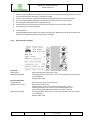
3.4 System Settings
System menu
Display Settings
Beep for Keypress enable/disable acoustic signal when a button is pressed

Manual for Operator Terminal
Power Control 3.0
25.03.2022 Rainer Bumberger 487.760 Manual Power Control 3.0 -
V1.1_en.docx 10 / 19
System Settings
Temperature Temperature inside the terminal
UB Voltage Measuring of the actual voltage
Tractor InCab Mode If Terminal is connected via the inCab connector of a tractor, this
function should be enabled.
Default: OFF
IMPORTANT: Using the PÖTTINGER Tractor cable and this option is enabled, the
implement won’t start!
UT Instance Default: 0
For using more than one ISOBUS Terminals. Only one terminal is allowed to have
instance 0, the second Terminal needs to be changed to 1.
Softkeys:
• Update USB - Developer cable is needed
• Touch Calibration
• Key Test
• Delete IOP Objectpool

Manual for Operator Terminal
Power Control 3.0
25.03.2022 Rainer Bumberger 487.760 Manual Power Control 3.0 -
V1.1_en.docx 11 / 19
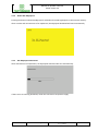
3.4.1 Touch calibration
Follow the instructions on the display. Press the shown cross symbols until the procedure is finished.

Manual for Operator Terminal
Power Control 3.0
25.03.2022 Rainer Bumberger 487.760 Manual Power Control 3.0 -
V1.1_en.docx 12 / 19
3.4.2 Delete IOP Objectpool
Pressing the button ‘Delete IOP Objectpool’ will delete all stored Opjectpools in the terminal memory.
After a restart and reconnection of an implement, the objectpool download will start automatically.
3.4.3 IOP Objectpool Download
After connection of an implement, the objectpool download will start automatically.
If there is an error during download, check the connections and power supply.

Manual for Operator Terminal
Power Control 3.0
25.03.2022 Rainer Bumberger 487.760 Manual Power Control 3.0 -
V1.1_en.docx 13 / 19

Manual for Operator Terminal
Power Control 3.0
25.03.2022 Rainer Bumberger 487.760 Manual Power Control 3.0 -
V1.1_en.docx 14 / 19
4 Electrical connectivity
Physical interface:
o A: M12-8pol male Main Connector to implement
o B: M12-8pol female To signal connector of the tractor
4.1 Pinout
A
B

Manual for Operator Terminal
Power Control 3.0
25.03.2022 Rainer Bumberger 487.760 Manual Power Control 3.0 -
V1.1_en.docx 15 / 19
4.2 Main Connector
Connection cable to implement (to 9-pole ISOBUS InCab Connector)
476.282
Adapterkabel AMP 9

Manual for Operator Terminal
Power Control 3.0
25.03.2022 Rainer Bumberger 487.760 Manual Power Control 3.0 -
V1.1_en.docx 16 / 19
5 TECU Tractor ECU
5.1 Tractor side pin allocation
A seven-pin female bulkhead connector shall be mounted on the tractor with the following pin allocation:
— Pin 1: true ground speed
— Pin 2: theoretical ground speed
— Pin 3: rear PTO rotational speed
— Pin 4: rear three-point implement in-work/out-of-work
— Pin 5: rear three-point linkage position
— Pin 6: power supply
— Pin 7: common ground
5.1.1 7-pole in-Cab signal connector ISO 11786
Connection to the 7-pole in-Cab signal connector DIN 9684
ISO 11786 (Agricultural tractors and machinery - Tractor mounted sensor interface)

Manual for Operator Terminal
Power Control 3.0
25.03.2022 Rainer Bumberger 487.760 Manual Power Control 3.0 -
V1.1_en.docx 17 / 19
5.2 Terminal side pin allocation
Connection Cable to 7-pole in-Cab connector:
PÖTTINGER No.:
476.374
Adapterkabel Amph.7pol P 2m M12 8pol PC 3.0<->Signalstd.
5.2.1 Tractor speed Input: 2 inputs ISO11786:1995 compliant :
• A 4700 ohm pull-up resistor, that can be enabled/disabled, to the power input voltage,
• Approximately 15000 ohm input impedance to ground with pull-up resistor disabled.
• Two input modes with different levels for low and high with hysteresis:
• MODE 1: High level 3420mV, Low level 2540mV
• MODE 2: High level 6280mV, Low level 1520mV
• Accuracy 2% of mode levels
• Default setting (by system menu) : Mode 1
• Protection
• Protected against shortcut
• Protected against shortcut to power
• Part of the M12 8-pole female connector
5.2.2 Rear PTO speed Input: 1input ISO11786:1995 (chapter 5.3) compliant:
• A 4700 ohm pull-up resistor, that can be enabled/disabled, to the power input voltage,
• Approximately 15000 ohm input impedance to ground with pull-up resistor disabled.
• Two input modes with different levels for low and high with hysteresis:

Manual for Operator Terminal
Power Control 3.0
25.03.2022 Rainer Bumberger 487.760 Manual Power Control 3.0 -
V1.1_en.docx 18 / 19
• MODE 1: High level 3420mV, Low level 2540mV
• MODE 2: High level 6280mV, Low level 1520mV
• Accuracy 2% of mode levels
• Default setting (by system menu) : Mode 1
• The signal shall be a square wave with a duty cycle between 20 % and 80 %, and with rise and
fall times less than 1 ms
• At rotational speeds greater than 2 r/s, the speed shall be represented by 6 pulses per revolu-
tion (6 Hz/r/s).
• Protection
• Protected against shortcut
• Protected against shortcut to power
• Part of the M12 8-pole female connector
5.2.3 Three-point Digital Input: 1input ISO11786:1995 (chpt. 5.4) compliant :
• Electrical properties:
• Signal levels: In-work signal: voltage less than 1.5 V Out-of-work signal: greater than 6.3V
• Source impedance at the in-work position: shall be 100 ± 10 Ohm
• Load impedance: greater than 3 kOhm
• Internal pull up for passive signa sources: switchable by software (System Menu). This function
is not part of the related standard.
• Protection
• Protected against shortcut
• Protected against shortcut to power
• Part of the M12 8-pole female connector
5.2.4 Three-point analog Input: 1input ISO11786:1995 chapter 5.5 compliant :
• Electrical properties of Linkage position input
• Voltage range: 0..10V
• Accuracy: better than 0.5% within the voltage range
• Load impedance: greater than 3 kOhm
• Protection
• Protected against shortcut
• Protected against shortcut to power
• Part of the M12-8pol female connector
5.2.5 Ignition In/Output: 1 channel In/output
• Output mode:
• max output current: 0.5A (high side switch)
• no freewheeling for inductive loads
• off delay setting by user PGN
• Input mode:
• Terminal able to start when connected to power (+12V) Cannot be use the Output mode to-
gether with the Ignition Input function!

Manual for Operator Terminal
Power Control 3.0
25.03.2022 Rainer Bumberger 487.760 Manual Power Control 3.0 -
V1.1_en.docx 19 / 19
• Forced boot mode: negative voltage connected (between -5 to -12V). (USB to RS232 update ca-
ble can be ordered.)
• Protection
• Protected against shortcut
• Protected against shortcut to power
Part of the M12-8pol male connector
5.3 EMC
5.3.1 EN ISO 14982:2009
Agricultural and forestry machinery -- Electromagnetic compatibility -- Test methods and ac-
ceptance criteria
5.4 ESD
5.4.1 EN ISO 10605
Test level ±6 kV for all pins for contact discharge.
Test level ±8 kV for all pins for air discharge.

A empresa PÖTTINGER Landtechnik GmbH
esforçase continuamente por melhorar os
seus produtos, adaptando-os à evolução
técnica.
Por este motivo, reservamonos o direito de modificar
as figuras e as descrições constantes no presente
manual, sem incorrer na obrigação de modificar
máquinas já fornecidas.
As características técnicas, as dimensões e os pesos
não são vinculativos.
A reprodução ou a tradução do presente manual de
instruções, seja ela total ou parcial, requer a autorização
por escrito da
PÖTTINGER
Landtechnik GmbH
A-4710 Grieskirchen
Todos os direitos estão protegidos pela lei da prop-
riedade intelectual.
Im Zuge der technischen Weiterentwicklung
arbeitet die PÖTTINGER Landtechnik
GmbH ständig an der Verbesserung ihrer
Produkte.
Änderungen gegenüber den Abbildungen und
Beschreibungen dieser Betriebsanleitung müssen wir
uns darum vorbehalten, ein Anspruch auf Änderungen
an bereits ausgelieferten Maschinen kann daraus nicht
abgeleitet werden.
Technische Angaben, Maße und Gewichte sind
unverbindlich. Irrtümer vorbehalten.
Nachdruck oder Übersetzung, auch auszugsweise,
nur mit schriftlicher Genehmigung der
PÖTTINGER
Landtechnik GmbH
A-4710 Grieskirchen.
Alle Rechte nach dem Gesetz des Urheberrecht
vorbehalten.
La société PÖTTINGER Landtechnik GmbH
améliore constamment ses produits grâce
au progrès technique.
C'est pourquoi nous nous réser-vons le droit de
modifier descriptions et illustrations de cette notice
d'utilisation, sans qu'on en puisse faire découler un
droit à modifications sur des machines déjà livrées.
Caractéristiques techniques, dimensions et poids sont
sans engagement. Des erreurs sont possibles.
Copie ou traduction, même d'extraits, seulement avec
la permission écrite de
PÖTTINGER
Landtechnik GmbH
A-4710 Grieskirchen.
Tous droits réservés selon la réglementation des
droits d'auteurs.
Following the policy of the PÖTTINGER
Landtechnik GmbH to improve their products
as technical developments continue,
PÖTTINGER reserve the right to make alterations which
must not necessarily correspond to text and illustrations
contai-ned in this publication, and without incurring
obligation to alter any machines previously delivered.
Technical data, dimensions and weights are given as
an indication only. Responsibility for errors or omissions
not accepted.
Reproduction or translation of this publication, in whole
or part, is not permitted without the written consent of the
PÖTTINGER
Landtechnik GmbH
A-4710 Grieskirchen.
All rights under the provision of the copyright Act are
reserved.
PÖTTINGER Landtechnik GmbH werkt
permanent aan de verbetering van hun
producten in het kader van hun technische
ontwikkelingen. Daarom moeten wij ons
veranderingen van de afbeeldingen en beschrijvingen
van deze gebruiksaanwijzing voorbehouden, zonder
dat daaruit een aanspraak op veranderingen van reeds
geieverde machines kan worden afgeleid.
Technische gegevens, maten en gewichten zijn niet
bindend. Vergissingen voorbehouden.
Nadruk of vertaling, ook gedeeltelijk, slechts met
schriftelijke toestemming van
PÖTTINGER
Landtechnik GmbH
A-4710 Grieskirchen.
Alle rechten naar de wet over het auteursrecht voor-
behouden.
La empresa PÖTTINGER Landtechnik
GmbH se esfuerza contínuamente en
la mejora constante de sus productos,
adaptándolos a la evolución técnica. Por ello
nos vemos obligados a reservarnos todos los derechos
de cualquier modificación de los productos con relación
a las ilustraciones y a los textos del presente manual,
sin que por ello pueda ser deducido derecho alguno a
la modificación de máquinas ya suministradas.
Los datos técnicos, las medidas y los pesos se
entienden sin compromiso alguno.
La reproducción o la traducción del presente manual
de instrucciones, aunque sea tan solo parcial, requiere
de la autorización por escrito de
PÖTTINGER
Landtechnik GmbH
A-4710 Grieskirchen.
Todos los derechos están protegidos por la ley de la
propiedad industrial.
La PÖTTINGER Landtechnik GmbH è
costantemente al lavoro per migliorare i suoi
prodotti mantenendoli aggiornati rispetto allo
sviluppo della tecnica.
Per questo motivo siamo costretti a riservarci la facoltà
di apportare eventuali modifiche alle illustrazioni e alle
descrizioni di queste istruzioni per l’uso. Allo stesso
tempo ciò non comporta il diritto di fare apportare
modifiche a macchine già fornite.
I dati tecnici, le misure e i pesi non sono impegnativi. Non
rispondiamo di eventuali errori. Ristampa o traduzione,
anche solo parziale, solo dietro consenso scritto della
PÖTTINGER
Landtechnik GmbH
A-4710 Grieskirchen.
Ci riserviamo tutti i diritti previsti dalla legge sul diritto
d’autore.
EN
IT
PT
NL
DE ES
FR
La pagina si sta caricando...
-
 1
1
-
 2
2
-
 3
3
-
 4
4
-
 5
5
-
 6
6
-
 7
7
-
 8
8
-
 9
9
-
 10
10
-
 11
11
-
 12
12
-
 13
13
-
 14
14
-
 15
15
-
 16
16
-
 17
17
-
 18
18
-
 19
19
-
 20
20
-
 21
21


Pottinger Control console PC3.0 LW Istruzioni per l'uso
- Tipo
- Istruzioni per l'uso
in altre lingue
Documenti correlati
-
Pottinger Control console PC3.0 LW Istruzioni per l'uso
-
-
-
-
-
-
-
-
-