Lince 1883ZENITHDT/E Istruzioni per l'uso
- Tipo
- Istruzioni per l'uso

IT RILEVATORE DI PRESENZA DOPPIA
TECNOLOGIA DA SOFFITTO
Manuale di installazione, programmazione ed uso.
- Istruzioni originali -
EN DUAL TECHNOLOGY CEILING
MOUNTING DETECTOR
Installation, programming and operating manual.
- Translation of original instructions -
ART./ITEM:
1883ZENITHDT/E
RILEVATORE
ZENITH DT/E
MADE IN ITALY
La dichiarazione CE del presente articolo è reperibile sul sito
www.lince.net.
L’installazione dei prodotti riportati nel presente manuale deve
essere eseguita da personale specializzato in possesso delle
dovute conoscenze tecniche; i prodotti sono stati progettati per
utilizzo in contesti domestici e civili.
The CE declaration of this item is available on www.lince.net
website.
The installation of the products listed in this manual must
be performed by specialized personnel with the necessary
technical knowledge; the products have been designed for use
in domestic and civil contexts.

LINCE ITALIA
2
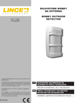
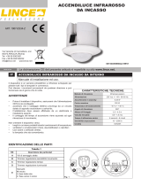
Fig. 1
CARATTERISTICHE TECNICHE
Sensore infrarosso Doppio elemento a basso rumore
Frequenza microonda 10,525 GHz strip line
Realizzazione del circuito SMT con microprocessore
Copertura 360°
Alimentazione 8 ÷ 16 Vcc
Assorbimento Stand-By 43 mA
Assorbimento max 50 mA
Relè di allarme N.C.silenzioso10Ωinserie
Installazione Soffitto
Switch antisabotaggio N.C. contatto dedicato
Funzione AND/OR Si
Temp. di funzionamento +5° ÷ +40 °C
Dimensioni ø 129 x 43 mm
Peso 109 g
DESCRIZIONE
Lo ZENITH DT/E riunisce in un unico dispositivo un sensibile
rilevatore a microonda ed un afdabile sensore ad infrarosso,
entrambi gestiti da una potente ed evoluta elettronica con
microprocessore.
Appositamente studiato e realizzato per il funzionamento in
ambienti difcili, garantisce un eccellente grado di immunità a
fenomeni che in altri tipi di rilevatori possono causare falsi allarmi.
La sequenza dei preallarmi forniti dai due sensori in esso contenuti
viene opportunamente analizzata dal microprocessore, evitando
così che fenomeni esterni come correnti d’aria, sorgenti di calore,
e disturbi di origine elettrica diano luogo ad indesiderati allarmi.
La realizzazione con componenti SMD ha reso possibile ottenere
dimensioni ridotte nonostante la complessità delle funzioni
svolte, una maggiore afdabilità del circuito e non ultima una
elevataimmunitàadisturbielettromagnetici.Èdotatodiindicatori
luminosiperlavericadelcorrettoposizionamentoeregolazione
disensibilità/portatadellamicroonda.Laprogrammazionedelle
funzioni del rilevatore si effettua tramite dip-switch.
INSTALLAZIONE
Il rilevatore offre prestazioni ottimali ed una elevata immunità
contro i falsi allarmi. L’installazione del rilevatore è esclusivamente
dasoftto,esiconsigliadiseguireleistruzioni
• togliere la copertura ruotandola in senso orario
(Opened).
• Effettuare i collegamenti.
• Chiudere il rilevatore facendo coincidere la
tacca di riferimento (Closed).
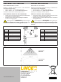
• Individuare il punto del softto più indicata al
ne di rilevare eventuali intrusi, attenendosi
al graco di copertura riportato in fondo al
presente manuale (maggiore è l’altezza del
softtomaggioresaràl’areaprotetta).
• Eventuali irregolarità del softto non sono da
considerarsi un problema per il ssaggio, in
quanto,inprossimitàdeiforidissaggiosono
state previste delle alette che permettono di
adattare la base alle irregolarità del piano di
ssaggio.
Le informazioni riportate in questo manuale sono state compilate con cura, tuttavia
l’azienda produttrice non può essere ritenuta responsabile per eventuali errori
e/o omissioni. L’azienda si riserva il diritto di apportare in ogni momento, e senza
preavviso, miglioramenti e/o modiche ai prodotti descritti nel presente manuale.
L’azienda pone particolare attenzione al rispetto dell’ambiente. Tutti i prodotti ed i
processi produttivi sono progettati con criteri di eco-compatibilità.
Il presente articolo è stato prodotto in Italia.
• L’azienda ha un sistema di gestione della qualità certicato secondo la
norma ISO 9001:2015 (n° 4796 - A)
• L’azienda ha un sistema di gestione ambientale certicato secondo la
norma ISO 14001:2015 (n° 4796 - E)
• L’azienda ha un sistema di gestione della salute e sicurezza sul lavoro
certicato secondo la norma ISO 45001:2018 (n° 4796 - I)
TECHNICAL FEATURES
Infrared sensor Double low noise element
Microwave frequency 10.525 GHz strip line
Circuit construction SMT with microprocessor
Range 360°
Power supply 8 ÷ 16 Vdc
Stand-By Consumption 43 mA
Max Cunsumption 50 mA
Alarm relay N.C.silent10Ωinseries
Installation Ceiling
Anti-tamper switch N.C. dedicated contact
AND/OR Function Yes
Operation temperature +5° ÷ +40 °C
Dimensions ø 129 x 43 mm
Weight 109 g
DESCRIPTION
ZENITH DT/E gathers in a single device a sensitive microwave
detector and a reliable infrared sensor, both controlled by
powerful and advanced electronics with microprocessor.
Especially designed and produced for operation in challenging
environments, it assures excellent degree of immunity to events
that in other types of detectors may cause false alarms.The
sequence of pre-alarms provided by the two sensors is suitably
analysed by the microprocessor, thus preventing external events
such as air drafts, heat sources and electrical disturbances
from triggering unnecessary alarms. Construction with SMD
components has resulted in compact dimensions despite the
complexity of functions performed, greater circuit reliability and
last but not least, high immunity to electromagnetic noise. It is
equipped with light indicators to check correct positioning and
microwave sensitivity/range adjustment. Detector functions are
programmed through dip-switches.
INSTALLATION
The detector offers optimal performances and high false alarm
immunity.
The detector is exclusively for ceiling installation and it is
recommended to comply with the following instructions:
• remove the cover by turning it clock-
wise (Opened).
• Perform connections.
• Close the detector so that mark
matches (Closed).
• Locate the most suitable point of the
ceiling in order to detect any intruders,
adhering to the range chart at the end
of this manual (higher is the ceiling,
wider is the protected area).
• Any ceiling unevenness should not
be considered as a problem for
fastening,sincensareprovidednear
the fastening holes to adapt the base
to fastening surface unevenness.
The information in this manual has been issued with care, but the company will
not be responsible for any errors or omissions. The company. reserves the right to
improve or modify the products described in this manual at any time and without
advance notice. The company makes it a priority to respect the environment. All
products and production processes are designed to be eco-friendly and sustainable.
This product has been Made in Italy.
• The company has a certied system of quality management according
to ISO 9001:2015 (n° 4796 - A) standard.
• The company has a certied system of environmental management
according to ISO 14001:2015 (n° 4796 - E) standard.
• The company has a certied system of health and work security
management according to 45001:2018 (n° 4796 - I) standard.

3
LINCE ITALIA
COLLEGAMENTI
I collegamenti con il rilevatore devono essere effettuati con
cavo schermato: collegare lo schermo alla massa della centrale
lasciandolo scollegato dalla parte del rilevatore. Se la distanza
tra il rilevatore e la centrale è notevole, assicurarsi che non vi sia
caduta di tensione. Per la descrizione dei morsetti fare riferimento
alla seguente tabella:
WT
Morsetto per l’esclusione a distanza dei LED di
allarme e abilitazione memoria (vedi paragrafo
Esclusione LED ed abilitazione memoria).
AS
Contatti dello switch antisabotaggio Normalmente
chiuso.
Collegare questi morsetti alla linea antisabotaggio.
NC Contatti del relé di allarme Normalmente Chiuso.
Collegare ad una linea di allarme.
+ / -
Morsetti di alimentazione 12Vcc, quando il
rilevatore viene alimentato impiega circa 60 s per
stabilizzarsi.
FUNZIONE DEI LED
LED giallo: Lampeggiante, la microonda sta rilevando del
movimento nell’ambiente
LED verde: Accesosso,ilsensoreinfrarossoharilevatouna
presenza
LED rosso: Accesosso,condizionediallarme.
ESCLUSIONE LED DI ALLARME
Il morsetto WT consente di escludere a distanza i led di allarme e
conseguentemente abilitare la memoria del rilevatore.
Per attivare questa funzione si deve inviare un positivo sul
morsetto WT a centrale disinserita E’ possibile eslcudere in modo
permanenteiLED,slandoiljumperpresentesullascheda(vedi
gura)
FUNZIONE AND/OR
In AND si ha l’allarme solo quando tutti e due i sensori rilevano
la causa, mentre in OR quando soltanto uno dei due si attiva.
Per attivare/disattivare le funzioni è necessario insirere/slare
il jumper presence sulla scheda (vedi gura): se il jumper è
presente è attiva la funzione AND, mentre se non è presente è
attiva la funzione OR.
COPERTURA
Il rilevatore battendo a terra termina la sua zona di rilevazione,
ma va considerato che la microonda (LED giallo) se non tarata
opportunamente potrebbe oltrepassare il pavimento ed andare a
rilevare persone o cose sottostanti, pertanto nelle applicazioni
dove sotto il pavimento c’è possibilità di passaggio, altre
abitazioni,ecc.siraccomandadiattenuarelasensibilità/portata
della microonda tramite il trimmer range.
PROVA DI COPERTURA
Eseguire una prova di portata del ZENITH DT/E aumentando
gradualmente la sensibilità della microonda tramite il trimmer
(range)alnediottenerel’accensionedelledgiallonoallimite
della zona da proteggere e non oltre. Succesivamente, regolare
lasensibilitàdelPIRinfrarossotramiteiltrimmerRANGEIR:tale
funzione è particolarmente utile in ambienti soggetti a spifferi
d’aria.
CONNECTIONS
Connections with the detector must be performed with shielded
cable: connect the shield to the control panel earth, leaving it
unconnected on the detector side.
Ifthedistancebetweendetectorandcontrolpanelissignicant,
ensure there is no voltage drop. Refer to the following table for a
description of terminals:
WT
Terminal block for remotely disabling alarm LEDs,
and enabling memory (see paragraph LED disable
and memory enable paragraph).
AS
Anti-tamper switch contacts Normally closed.
Connect these terminal blocks to the anti-tamper
line.
NC Alarm relay contacts Normally closed:
Connect to an alarm line.
+ / -
12Vcc power supply terminal blocks, when the
detector is powered it takes about 60 s to stabilise.
LED FUNCTION
Yellow LED: Flashing, the microwave is detecting motion in the
room
Green LED: Steady on, the infrared sensor has detected a
presence
Red LED: Steady on, alarm condition.
ALARM LED DISABLE
The WT terminal block remotely disables alarm LEDs and
consequently enables detector memory. To activate this function,
a positive (present with system disarmed) must be sent to WT
terminal block. It is possible to permanently disable the LEDs by
removing the jumper on the board (see picture).
AND/OR FUNCTION
In AND the alarm is triggered only when both sensors detect the
cause, whereas in OR when only one of the two is activated. To
enable/disable the tow function is necessary insert/remove the
realtive jumper (see pciture): if the jumper is present the AND
function is activated; while if the jumper is not present is activated
the OR function.
RANGE
When the detector hits the ground its detection zone ends, but
one should consider that if not properly calibrated, the microwave
(yellowLED)mightgothroughtheoorandtodetectpeopleor
objectsbelow,soinapplicationswheretransitundertheooris
possible, other dwellings downstairs etc. it is recommended to
tune the microwave sensitivity/range through the range trimmer.
RANGE TEST
Where the ZENITH DT/E is installed, test the covering by
gradually increase the microwave’s sensitivity range (trimmer) so
that the yellow led lights up til the zone to protect and not over.
Subsequently, adjust the sensitivity of the infrared PIR IR trimmer
RANGE; this function is especially useful in locations where air
drafts.Tondthetwojumpers,pleaserefertogure2.

LINCE ITALIA
4
001530/00847AB Rev. 00
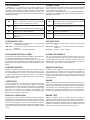
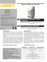
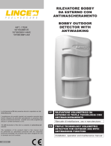
Fig. 2
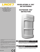
Fig. 3
LINCE ITALIA S.r.l.
Via Variante di Cancelliera, snc
00072 Ariccia (Roma)
Tel. +39 06 9301801
Fax +39 06 930180232
www.lince.net
Vista laterale
Side view
Vista dall’alto
Side view
AA
E
F
G
B
D
C
PARTE DESCRIZIONE
A Morsettiera
B Jumper esclusione LED
C LED di segnalazione
DJumper AND/OR
E Trimmer MW
F Microswitch antisabotaggio
G Trimmer IR
SMALTIMENTO E ROTTAMAZIONE
SMALTIMENTO IMBALLAGGIO
Smaltire il materiale di imballo secondo i codici identicativi
riportati sul materiale stesso:
• PAP 20 / PAP 21 – raccolta differenziata carta;
• PVC 3 / LDPE 4 / O 7 – raccolta differenziata plastica.
Vericareilsistemadiraccoltadelpropriocomune.
SMALTIMENTO PRODOTTO E ROTTAMAZIONE
• Svitare il fondo, rimuovere la pila e tutte le parti del prodotto
quali scheda e contenitore plastico;
• Dividere le parti in base alla loro tipologia e smaltirle in
accordo con le leggi vigenti.
ATTENZIONE!
Non disperdere nell’ambiente i componenti ed ogni
altro materiale del prodotto. Rivolgersi a consorzi
abilitati allo smaltimento ed al riciclaggio dei materiali.
DISPOSAL AND SCRAPPING
DISPOSAL OF PACKAGING
Disposeofthepackagingmaterialaccordingtotheidentication
codes shown on the material itself:
• PAP 20 / PAP 21 - separate paper collection;
• PVC 3 / LDPE 4 / O 7 - plastic separate collection.
Check your municipality's collection system.
PRODUCT DISPOSAL AND SCRAPPING
• Unscrew the bottom, remove the battery and all parts of the
product such as the board and plastic case;
• Divide the parts by type and dispose of them in accordance
with applicable laws.
IMPORTANT!
Do not dispose of the components or any other pro-
duct material in the environment. Seek the assistan-
ce of companies authorised to dispose of and recycle waste
materials.
PART DESCRIPTION
A Terminal block
B LED jumper exclusion
C Signaling LEDs
D AND/OR jumper
E MW trimmer
F Antitamper microswitch
G IR trimmer
-
 1
1
-
 2
2
-
 3
3
-
 4
4


Lince 1883ZENITHDT/E Istruzioni per l'uso
- Tipo
- Istruzioni per l'uso
in altre lingue
Documenti correlati
-
 Lince 1597ZENITHDT Istruzioni per l'uso
-
 Lince 1673BOBBY Istruzioni per l'uso
-
 Lince 1497DTP100 Istruzioni per l'uso
-
 Lince 1947-BOBBY180-E-AM Istruzioni per l'uso
-
 Lince 9553-GOLD-BOBBY-AM-E Istruzioni per l'uso
-
 Lince 1630DT/JOLLY Istruzioni per l'uso
-
 Lince 1967-ES34-Z Istruzioni per l'uso
-
 Lince 1875BOBBY-AM/E Istruzioni per l'uso
-
 Lince 1866BABY-BA/E Istruzioni per l'uso
-
 Lince 1830DT/JOLLY-E Istruzioni per l'uso


