Peerless DS-S555-4X3 Guida d'installazione
- Categoria
- Parete
- Tipo
- Guida d'installazione

12015-06-24 #:009-9117-4 (2018-03-08)
ENG
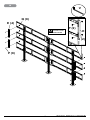
DS-S555-4X3
46" - 55"
(117 - 140 cm)
1200 lb
(544 kg)
MAX

22015-06-24 #:009-9117-4 (2018-03-08)
Symbols
ENG
WARNING
ENG
x3
Screws must get at
least three full turns
and t snug.
ENG
Do not overtighten screws.
ENG
Display center.
ENG
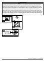
ENG - Do not begin to install product until you have read and understood the instructions and warnings
contained in this user guide. Always use an assistant or mechanical lifting equipment to safely lift and position
equipment. This product must be installed onto at, hard, level surface to prevent tipping. Use with heavier
displays may result in instability causing tip over resulting in death or serious injury. Displays must be removed
before moving cart. Not recommended for use in areas with heavy trafc. This product is intended for indoor use
only. Use of this product outdoors could lead to product failure or personal injury. Screws must be tightly secured.
Do not overtighten screws or damage can occur and product may fail. Never exceed the Maximum Load
Capacity. Be careful not to pinch ngers when operating the mount. Death or serious injury may occur when
children climb on audio and/or video equipment furniture. A remote control or toys placed on the furnishing may
encourage a child to climb on the furnishing and as a result the furnishing may tip over on to the child. Relocating
audio and/or video equipment to furniture not specically designed to support audio and/or video equipment may
result in death or serious injury due to the furnishing collapsing or over turning onto a child. For support please
call customer care at 1-800-865-2112.
WARNING

32015-06-24 #:009-9117-4 (2018-03-08)
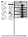
Tools Needed for Assembly.
ENG
3/8"
(10mm)
3/8"
(10mm)
To properly tighten screws: Tighten until screw
head makes contact, then tighten another 1/2
turn. Do not overtighten screws.
1
2
+1/2
4
3

42015-06-24 #:009-9117-4 (2018-03-08)
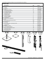
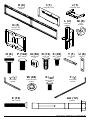
Parts (Before beginning, make sure you have all parts shown below).
Parts List
Part #Description Qty
Apedestal 3 146-T1132
Bcolumn 3 146-T1131
Cextension 3145-T1778
Dcover 3 145-T1809
Eside support bracket 4 145-T1807
Fvertical support bracket 6 145-T1806
Gleft adaptor bracket 12 146-1609
Hright adaptor bracket 12 146-1608
Icomputer cover 1 145-T1930
Jcomputer shelf 1 145-T1931
Kdual cross support 6 146-T1905
Lextension adaptor 3145-T1935
Mcord bracket 6 146-T1321
Nbracket, 4x2 conguration 3145-T1858
Oknob 6 560-1160
PM8 x 16mm socket button screw 140 520-9527
QM8 square nut 56 530-1066
Rcover clip 12 590-0317
SM5 x 10mm type-f, socket pin screw 26 520-1164
T1/4" power bit 1 560-0263
Ubar nut 6 146-1319
V5mm allen wrench 1 560-9640
Wnylon shoulder washer 48 590-2233
XM6 x 12mm socket pin screw 48 520-1050
Y4mm allen wrench 1 560-9646
ZM6 x 35mm screw 12 520-0717
AA rawl bolt #6913 12 5M9-381-H03
D (3)
cover
B (3)
column
F (6)
vertical support
bracket
E (4)
side support
bracket
A (3)
pedestal
C (3)
extension
H (12)
right adaptor
bracket
G (12)
left adaptor
bracket

52015-06-24 #:009-9117-4 (2018-03-08)
I (1)
computer cover
J (1)
computer shelf
N (3)
bracket, 4x2
conguration
K (6)
dual cross
support
Y (1)
4mm allen
wrench
P (140)
M8 x 16mm
Q (56)
M8 square
nut
R (12)
cover clip
S (26)
M5 x 10mm T (1)
1/4" power
bit
V (1)
5mm allen
wrench
W (48)
nylon shoulder
washer
X (48)
M6 x 12mm
L (3)
extension
adaptor
rawl bolt
AA (12)
M6 x 35mm
Z (12)
M (6)
cord
bracket
O (6)
knob bar nut
U (6)

62015-06-24 #:009-9117-4 (2018-03-08)
Z (4)
AB
2-1
Do not fully tighten hardware
P (4)
U (2)
L
TOP VIEW
x3
1
x3
V

72015-06-24 #:009-9117-4 (2018-03-08)
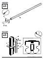
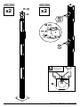
2-2
TIGHTEN
CONNECTING
HARDWARE
x3
C
B
V

82015-06-24 #:009-9117-4 (2018-03-08)
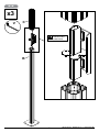
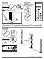
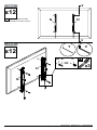
3-1
3-2
P (6)
Q (4)
F
x6
1/8"
(3mm)
1/8"
(3mm)
TIGHTEN
CONNECTING
HARDWARE
DISPLAY HEIGHT
DISPLAY HEIGHT
x2
V
V

92015-06-24 #:009-9117-4 (2018-03-08)
4
x2x2
5
M (2)
O (2)
TOP VIEW
MO
TIGHTEN
CONNECTING
HARDWARE
R (4)
D

10 2015-06-24 #:009-9117-4 (2018-03-08)
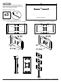
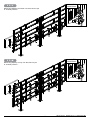
6-1
Use metric formula below and diagram to
right to determine hole pattern required for
center vertical support bracket.
All dimensions are metric.
Use the outside mounting holes when…
a x 4 > 4368mm and a x 3 + b < 4318mm
Use the inside mounting holes when…
a x 4 > 4098mm and a x 3 + b < 4064mm
P (12)
Q (8)
N
Q (8)
N
P (12)
BACK
SIDE
1/8"
(3mm)
b
a
BACK OF DISPLAY
x3 V

11 2015-06-24 #:009-9117-4 (2018-03-08)
DISPLAY HEIGHT
6-3
6-2
M
O
TOP VIEW
MO
TIGHTEN
CONNECTING
HARDWARE
B

12 2015-06-24 #:009-9117-4 (2018-03-08)
7
ENG - When installing Peerless mounts on a concrete oor, the oor must be at least 8" thick with a minimum
compressive strength of 2000 psi. Never attach concrete expansion anchors to concrete covered with plaster,
drywall, or other nishing material.
WARNING
FRN - Lors de l’installation de supports de plafond Peerless sur un plafond en béton, celui-ci doit avoir au moins
8 po (20 cm) d'épaisseur et une résistance à la compression d'au moins 2 000 psi. Ne xez jamais des chevilles
à expansion pour béton à du béton recouvert d’une couche de plâtre, d’une cloison sèche ou de tout autre
matériau de nition.
ADVERTISSEMENT
ESP - Cuando vaya a instalar soportes de techo de Peerless en techos de concreto, los techos tienen que
tener, por lo menos, 8" de grosor con una resistencia a la compresión de 2000 psi como mínimo. Nunca je los
anclajes de expansión para concreto a supercies de concreto recubiertas con yeso, yeso-cartón u otro material
de acabado.
ADVERTENCIA
DEU - Werden Peerless-Deckenhalter an einer Betondecke angebracht, so muss deren Dicke mindestens 203
mm (8 Zoll) und ihre Druckfestigkeit mindestens 13,8 N/mm2 (2000 psi) betragen. Betonspreizdübel dürfen
auf keinen Fall an Beton befestigt werden, der mit Verputz, Trockenwand- oder anderem Deckschichtmaterial
bedeckt ist.
ACHTUNG
WAARSCHUWING
NEL - Als de Peerless-plafondbevestiging op een betonnen plafond wordt geïnstalleerd, moet dit plafond een
dikte van ten minste 20 cm hebben en een druksterkte van ten minste 2000 psi. Gebruik nooit expansie-ankers
voor beton bij installatie op een betonnen plafond bedekt met gips, gipsplaat of ander afwerkingsmateriaal.
ITL - In sede d’installazione dei sostegni Peerless su un softto in calcestruzzo solido, il softto deve avere
uno spessore minimo di 20 cm, con una resistenza alla compressione di almeno 2000 psi (140 kg/cm2). Non
attaccare mai ancoranti a espansione per calcestruzzo su calcestruzzo ricoperto con intonaco, cartongesso o
altro materiale di nitura.
AVVERTENZA
ČEŠ - Při instalaci stropních držáků Peerless na betonový strop musí být tento trop hrubý minimálně 20 cm s
minimální pevností v tlaku 2000 psi. Expanzní kotvy do betonu nikdy nepřipojujte do betonu pokrytého omítkou,
sádrokartonem nebo jiným dokončovacím materiálem.
VÝSTRAHA
TÜR - Peerless tavan kaidelerini beton duvara monte ettiğinizde, tavan en azından 2000 psi asgari basınç
dayanımına sahip olmalı ve kalınlığı da en azından 8" olmalıdır. Beton dübelleri hiç bir zaman alçı, alçıpan veya
başka bir bitirme materyali ile kaplı betona takmayınız.
UYARI
AVISO
POR - Ao instalar os suportes para o teto Peerless em tetos de betão, o teto deve ter, no mínimo, 203 mm de
espessura e uma força de compressão mínima de 2000 psi. Nunca instale âncoras de expansão para betão em
superfícies cobertas com estuque, gesso ou outros materiais de acabamento.
SLK - Pri montáži stropných držiakov Peerless na betónový strop musí mať tento strop hrúbku minimálne 20 cm
s minimálnou tlakovou pevnosťou 2000 psi. Expanzné kotvy do betónu nikdy nenasadzujte do betónu pokrytého
omietkou, sadrokartónom či iným nalizačným materiálom.
VÝSTRAHA

13 2015-06-24 #:009-9117-4 (2018-03-08)
4
3"
(76mm)
3/8"
(10mm)
7-1
Align base. Mark mounting holes.
ENG
7-2
Drill mounting holes into
supporting surface
(3" (76mm) minimum
depth required).
ENG
3/8"
(10mm)
7-3
Align base. Install using concrete anchors
provided.
ENG
3/8"
(10mm)
55.00"
(1397mm)
55.00"
(1397mm)
ENG Maximum 35 ft • lb (47 N.M.).
AA (12)
55.00"
(1397mm)
55.00"
(1397mm)

14 2015-06-24 #:009-9117-4 (2018-03-08)
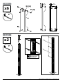
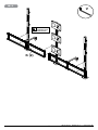
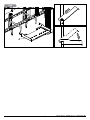
8-1
TIGHTEN
CONNECTING
HARDWARE
K (2)
V

15 2015-06-24 #:009-9117-4 (2018-03-08)
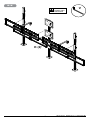
8-2
TIGHTEN
CONNECTING
HARDWARE
K (2)
V

16 2015-06-24 #:009-9117-4 (2018-03-08)
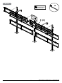
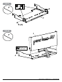
8-3
TIGHTEN
CONNECTING
HARDWARE
K (2)
V

17 2015-06-24 #:009-9117-4 (2018-03-08)
TIGHTEN
CONNECTING
HARDWARE
9
E
P (2)
Q (2)
P (8)
Q (8)
E (4)
V

18 2015-06-24 #:009-9117-4 (2018-03-08)
X
X
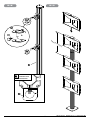
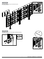
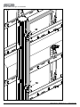
10-1
H
G
10-2
Center adapter brackets
vertically on back of screen.
ENG
H
G
x3
W X P
OR
V
x12
x12 Y

19 2015-06-24 #:009-9117-4 (2018-03-08)
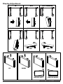
11-1
11-2
Must hang displays to bottom row rst; Secure pin
in "locked" position.
Must hang displays on top row last; Secure pin
in "locked" position.
"LOCKED"
POSITION
"LOCKED"
POSITION

20 2015-06-24 #:009-9117-4 (2018-03-08)
11-3
Must hang displays on top row last; Secure pin
in "locked" position.
"LOCKED"
POSITION
11-4
OPTIONAL: Insert M5 x 10mm type-F socket pin screws
(S) to lock latches. Y
S
"LOCKED"
POSITION
x24
La pagina sta caricando ...
La pagina sta caricando ...
La pagina sta caricando ...
La pagina sta caricando ...
La pagina sta caricando ...
La pagina sta caricando ...
La pagina sta caricando ...
La pagina sta caricando ...
-
 1
1
-
 2
2
-
 3
3
-
 4
4
-
 5
5
-
 6
6
-
 7
7
-
 8
8
-
 9
9
-
 10
10
-
 11
11
-
 12
12
-
 13
13
-
 14
14
-
 15
15
-
 16
16
-
 17
17
-
 18
18
-
 19
19
-
 20
20
-
 21
21
-
 22
22
-
 23
23
-
 24
24
-
 25
25
-
 26
26
-
 27
27
-
 28
28


Peerless DS-S555-4X3 Guida d'installazione
- Categoria
- Parete
- Tipo
- Guida d'installazione
in altre lingue
- English: Peerless DS-S555-4X3 Installation guide
- français: Peerless DS-S555-4X3 Guide d'installation
Documenti correlati
-
Peerless DS-S560-1X3 Guida d'installazione
-
-
-
-
-
-
-
-