Hitachi DV 18DJL Handling Instructions Manual
- Categoria
- Utensili elettrici
- Tipo
- Handling Instructions Manual
Questo manuale è adatto anche per

Cordless Impact Driver Drill
Akku-Schlagbohrschrauber
Perceuse percussion/visseuse à batterie
Trapano avvitatore a percussione a batteria
Snoerloze klop-boor-schroefmachine
Taladro atornillador de impacto a batería
Berbequim aparafusador de impacto a bateria
Read through carefully and understand these instructions before use.
Diese Anleitung vor Benutzung des Werkzeugs sorgfältig durchlesen und verstehen.
Lire soigneusement et bien assimiler ces instructions avant usage.
Prima dell’uso leggere attentamente e comprendere queste instruzioni.
Deze gebruiksaanwijzing s.v.p. voor gebruik zorgvuldig doorlezen.
Leer cuidadosamente y comprender estas instrucciones antes del uso.
Antes de usar, leia com cuidado para assimilar estas instruções.
Handling instructions
Bedienungsanleitung
Mode d’emploi
Istruzioni per l’uso
Gebruiksaanwijzing
Instrucciones de manejo
Instruções de uso
DV 14DJL
•
DV 18DJL
DV18DJL

1 2
3 4
5 6 7
8 9 10
2
ë
í
ì
î
ï
î
è
ï
äËÝïèÇÚÍÔâäËÝïèÇÕÍÔâ
ÿ
ü
ý
à
ÿ
÷
®
ê
é
ü
û
ú
ö
¯
©
¬
»
§
ï
ï
ð
ç
ç
ð
Â
ø
ö
§
®

11 12
3
±
·
«
·
«

4
English Deutsch Français Italiano
ï
Rechargeable battery Aufl adbare Batterie Batterie rechargeable Batteria ricaricabile
î Latch Verriegelung Taquet Fermo
í
Battery cover Akkuabdeckung Couvercle de la batterie Coperchio della batteria
ì
Terminal Anschluss Borne Terminale
ë Ventilator Lüfter Ventilateur Ventola
ê Push Drücken Pousser Premere
é
Pull out Herausziehen Tirer vers l’extérieur Estrarre
è Handle Handgri Poignée Impugnatura
ç Charger Ladegerät Chargeur Caricatore
ð
Pilot lamp Kontorollampe Lampe témoin Spia
ÿ Drill mark Bohrer-Zeichen Indice de forage Simbolo di foratura
à Hammer mark Hammermarkierung Repère de percussion Segno del martello
ý Clutch dial Kupplungsskala Sélecteur de débrayage Ghiera frizione
ü
Triangle mark Dreiecksmarkierung Triangle Simbolo del triangolo
û
Weak Schwach Faible Debol
Â
Strong Stark Fort Forte
ú Line Linie Ligne Linea
ö
Shift knob Schaltknopf Bouton de décalage Manopola di comando
ø
Low speed Kleine Geschwindigkeit Vitesse ralentie Bassa velocità
÷
High speed Große Geschwindigkeit Vitesse élevée Alta velocità
¯
Sleeve Manschette Manchon Collare
©
Tighten Anziehen Serrer Stringere
»
Loosen Lösen Desserrer Allentare
®
Trigger switch Trigger Déclencheur Interruttore
¬
Selector button Wählhebel Sélecteur Selettore
§
Î
and
Ô
marks
Î
und
Ô
Zeichen Indices
Î
et
Ô
Segno
Î
,
Ô
«
Screw Schraube Vis Vite
· Hook Haken Crochet Gancio
±
Groove Nut Gorge Scanalatura

5
Nederlands Español Português
ï
Oplaadbare batterij Batería recargable Bateria recarregável
î Vergrendeling Cierre Lingüeta
í
Batterijdeksel Tapa de la batería Tampa da bateria
ì
Klem Terminal Terminal
ë Ventilator Ventilador Ventilador
ê Duwen Pulsador Premir
é
Uittrekken Sacar Retirar
è Handgreep Asidero Cabo
ç Acculader Chargador Recarregador
ð
Controlelampje Lámpara piloto Lâmpada piloto
ÿ Boor-markering Marca del taladro Símbolo da broca
à Hammer markering Marca de martillo Marca do martelo
ý Koppelingsinstelling Dial del embrague Disco de engate
ü
Driehoekje Marca de triángulo Marca de triângulo
û
Zwak Débil Fraco
Â
Sterk Fuerte Forte
ú Streepje Línea Linha
ö
Toerenschakelaar Mando de cambio Comutador
ø
Laag toerental Velocidad alta Velocidade baixa
÷
Hoog toerental Velocidad baja Velocidade alta
¯
Klembus Manguito Manguito
©
Aandraaien Apretar Apertar
»
Losdraaien Afl ojar Afrouxar
®
Trekkerschakelaar Conmutador de gatillo Interruptor de comando
¬
Omzetschakelaar Botón selector Botão seletor
§
Î
en
Ô
merktekens Marcas
Î
y
Ô
Marcas
Î
e
Ô
«
Schroef Tornillo Parafuso
· Haak Gancho Gancho
±
Groef Ranura Ranhura

6
English Deutsch Français
Italiano
Symbols
WARNING
The following show
symbols used for the
machine. Be sure that you
understand their meaning
before use.
Symbole
WARNUNG
Die folgenden Symbole
werden für diese Maschine
verwendet. Achten Sie darauf,
diese vor der Verwendung zu
verstehen.
Symboles
AVERTISSEMENT
Les symboles suivants sont
utilisés pour l’outil. Bien
se familiariser avec leur
signifi cation avant d’utiliser
l’outil.
Simboli
AVVERTENZA
Di seguito mostriamo i
simboli usati per la macchina.
Assicurarsi di comprenderne il
signifi cato prima dell’uso.
Read all safety warnings
and all instructions.
Failure to follow the
warnings and instructions
may result in electric shock,
fi re and/or serious injury.
Lesen Sie sämtliche
Sicherheitshinweise und
Anweisungen durch.
Wenn die Warnungen
und Anweisungen nicht
befolgt werden, kann es
zu Stromschlag, Brand
und/oder ernsthaften
Verletzungen kommen.
Lire tous les
avertissements de
sécurité et toutes les
instructions.
Tout manquement à observer
ces avertissements et
instructions peut engendrer
des chocs électriques, des
incendies et/ou des blessures
graves.
Leggere tutti gli
avvertimenti di sicurezza
e tutte le istruzioni.
La mancata osservanza
degli avvertimenti e delle
istruzioni potrebbe essere
causa di scosse elettriche,
incendi e/o gravi lesioni.
Only for EU countries
Do not dispose of electric tools
together with household waste
material!
In observance of European
Directive 2002/96/EC on
waste electrical and electronic
equipment and its implementation
in accordance with national law,
electric tools that have reached
the end of their life must be
collected separately and returned
to an environmentally compatible
recycling facility.
Nur für EU-Länder
Werfen Sie Elektrowerkzeuge
nicht in den Hausmüll!
Gemäss Europäischer
Richtlinie 2002/96/EG über
Elektro- und Elektronik-
Altgeräte und Umsetzung
in nationales Recht müssen
verbrauchte Elektrowerkzeuge
getrennt gesammelt und
einer umweltgerechten
Wiederververtung zugeführt
werden.
Pour les pays européens
uniquement
Ne pas jeter les appareils
électriques dans les ordures
ménagères!
Conformément à la directive
européenne 2002/96/EG relative
aux déchets d’équipements
électriques ou électroniques
(DEEE), et à sa transposition
dans la législation nationale, les
appareils électriques doivent être
collectés à part et être soumis
à un recyclage respectueux de
l’environnement.
Solo per Paesi UE
Non gettare le apparecchiature
elettriche tra i rifi uti domestici.
Secondo la Direttiva Europea
2002/96/CE sui rifi uti di
apparecchiature elettriche ed
elettroniche e la sua attuazione in
conformità alle norme nazionali,
le apparecchiature elettriche
esauste devono essere raccolte
separatamente, al fi ne di essere
reimpiegate in modo eco-
compatibile.
Nederlands Español Português
Symbolen
WAARSCHUWING
Hieronder staan symbolen
afgebeeld die van
toepassing zijn op deze
machine. U moet de
betekenis hiervan begrijpen
voor gebruik.
Símbolos
ADVERTENCIA
A continuación se
muestran los símbolos
usados para la máquina.
Asegúrese de comprender
su signifi cado antes del
uso.
Símbolos
AVISO
A seguir aparecem os
símbolos utilizados pela
máquina. Assimile bem
seus signifi cados antes
do uso.
Lees alle
waarschuwingen en
instructies aandachtig
door.
Nalating om de
waarschuwingen en
instructies op te volgen kan
in een elektrische schok,
brand en/of ernstig letsel
resulteren.
Lea todas las
instrucciones y
advertencias de
seguridad.
Si no se siguen
las advertencias e
instrucciones, podría
producirse una descarga
eléctrica, un incendio y/o
daños graves.
Leia todas as instruções
e avisos de segurança.
Se não seguir todas as
instruções e os avisos,
pode provocar um choque
eléctrico, incêndio e/ou
ferimentos graves.
Alleen voor EU-landen
Geef elektrisch gereedschap niet
met het huisvuil mee!
Volgens de Europese richtlijn
2002/96/EG inzake oude
elektrische en elektronische
apparaten en de toepassing
daarvan binnen de nationale
wetgeving, dient gebruikt
elektrisch gereedschap
gescheiden te worden ingezameld
en te worden afgevoerd naar een
recycle bedrijf dat voldoet aan de
geldende milieu-eisen
.
Sólo para países de la Unión
Europea
¡No deseche los aparatos eléctricos
junto con los residuos domésticos!
De conformidad con la Directiva
Europea 2002/96/CE sobre
residuos de aparatos eléctricos
y electrónicos y su aplicación de
acuerdo con la legislación nacional,
las herramientas eléctricas cuya
vida útil haya llegado a su fi n se
deberán recoger por separado y
trasladar a una planta de reciclaje
que cumpla con las exigencias
ecológicas.
Apenas para países da UE
Não deite ferramentas eléctricas
no lixo doméstico!
De acordo com a directiva
europeia 2002/96/CE sobre
ferramentas eléctricas e
electrónicas usadas e a
transposição para as leis
nacionais, as ferramentas
eléctricas usadas devem ser
recolhidas em separado e
encaminhadas a uma instalação
de reciclagem dos materiais
ecológica.

English
7
GENERAL POWER TOOL SAFETY WARNINGS
WARNING
Read all safety warnings and all instructions.
Failure to follow the warnings and instructions may result in
electric shock, fi re and/or serious injury.
Save all warnings and instructions for future reference.
The term “power tool” in the warnings refers to your mains-
operated (corded) power tool or battery-operated (cordless)
power tool.
1) Work area safety
a) Keep work area clean and well lit.
Cluttered or dark areas invite accidents.
b) Do not operate power tools in explosive
atmospheres, such as in the presence of
fl ammable liquids, gases or dust.
Power tools create sparks which may ignite the dust
or fumes.
c) Keep children and bystanders away while
operating a power tool.
Distractions can cause you to lose control.
2) Electrical safety
a) Power tool plugs must match the outlet.
Never modify the plug in any way.
Do not use any adapter plugs with earthed
(grounded) power tools.
Unmodifi ed plugs and matching outlets will reduce
risk of electric shock.
b) Avoid body contact with earthed or grounded
surfaces, such as pipes, radiators, ranges and
refrigerators.
There is an increased risk of electric shock if your
body is earthed or grounded.
c) Do not expose power tools to rain or wet
conditions.
Water entering a power tool will increase the risk of
electric shock.
d) Do not abuse the cord. Never use the cord for
carrying, pulling or unplugging the power tool.
Keep cord away from heat, oil, sharp edges or
moving parts.
Damaged or entangled cords increase the risk of
electric shock.
e) When operating a power tool outdoors, use an
extension cord suitable for outdoor use.
Use of a cord suitable for outdoor use reduces the
risk of electric shock.
f) If operating a power tool in a damp location
is unavoidable, use a residual current device
(RCD) protected supply.
Use of an RCD reduces the risk of electric shock.
3) Personal safety
a) Stay alert, watch what you are doing and use
common sense when operating a power tool.
Do not use a power tool while you are tired
or under the infl uence of drugs, alcohol or
medication.
A moment of inattention while operating power tools
may result in serious personal injury.
b) Use personal protective equipment. Always wear
eye protection.
Protective equipment such as dust mask, non-skid
safety shoes, hard hat, or hearing protection used for
appropriate conditions will reduce personal injuries.
c) Prevent unintentional starting. Ensure the
switch is in the o -position before connecting to
power source and/or battery pack, picking up or
carrying the tool.
Carrying power tools with your fi nger on the switch or
energising power tools that have the switch on invites
accidents.
d) Remove any adjusting key or wrench before
turning the power tool on.
A wrench or a key left attached to a rotating part of the
power tool may result in personal injury.
e) Do not overreach. Keep proper footing and
balance at all times.
This enables better control of the power tool in
unexpected situations.
f) Dress properly. Do not wear loose clothing or
jewellery. Keep your hair, clothing and gloves
away from moving parts.
Loose clothes, jewellery or long hair can be caught in
moving parts.
g) If devices are provided for the connection of
dust extraction and collection facilities, ensure
these are connected and properly used.
Use of dust collection can reduce dust related
hazards.
4) Power tool use and care
a) Do not force the power tool. Use the correct
power tool for your application.
The correct power tool will do the job better and safer
at the rate for which it was designed.
b) Do not use the power tool if the switch does not
turn it on and o .
Any power tool that cannot be controlled with the
switch is dangerous and must be repaired.
c) Disconnect the plug from the power source and/
or the battery pack from the power tool before
making any adjustments, changing accessories,
or storing power tools.
Such preventive safety measures reduce the risk of
starting the power tool accidentally.
d) Store idle power tools out of the reach of children
and do not allow persons unfamiliar with the
power tool or these instructions to operate the
power tool.
Power tools are dangerous in the hands of untrained
users.
e) Maintain power tools. Check for misalignment or
binding of moving parts, breakage of parts and
any other condition that may a ect the power
tools’ operation.
If damaged, have the power tool repaired before
use.
Many accidents are caused by poorly maintained
power tools.
f) Keep cutting tools sharp and clean.
Properly maintained cutting tools with sharp cutting
edges are less likely to bind and are easier to
control.
g) Use the power tool, accessories and tool bits
etc. in accordance with these instructions,
taking into account the working conditions and
the work to be performed.
Use of the power tool for operations di erent from
those intended could result in a hazardous situation.
5) Battery tool use and care
a) Recharge only with the charger specifi ed by the
manufacturer.
A charger that is suitable for one type of battery pack
may create a risk of fi re when used with another
battery pack.
b) Use power tools only with specifi cally designated
battery packs.
Use of any other battery packs may create a risk of
injury and fi re.
(Original instructions)

English
8
c) When battery pack is not in use, keep it away
from other metal objects like paper clips, coins,
keys, nails, screws, or other small metal objects
that can make a connection from one terminal to
another.
Shorting the battery terminals together may cause
burns or a fi re.
d) Under abusive conditions, liquid may be ejected
from the battery; avoid contact. If contact
accidentally occurs, fl ush with water. If liquid
contacts eyes, additionally seek medical help.
Liquid ejected from the battery may cause irritation or
burns.
6) Service
a) Have your power tool serviced by a qualifi ed
repair person using only identical replacement
parts.
This will ensure that the safety of the power tool is
maintained.
PRECAUTION
Keep children and infi rm persons away.
When not in use, tools should be stored out of reach of
children and infi rm persons.
CORDLESS IMPACT DRIVER DRILL SAFETY
WARNINGS
1. Wear ear protectors when impact drilling.
Exposure to noise can cause hearing loss.
2. Use auxiliary handle(s), if supplied with the tool.
Loss of control can cause personal injury.
3. Hold power tool by insulated gripping surfaces,
when performing an operation where the cutting
accessory or fastener may contact hidden wiring.
Cutting accessory or fasteners contacting a “live” wire
may make exposed metal parts of the power tool “live”
and could give the operator an electric shock.
4. Always charge the battery at a temperature of 0°C –
40°C. A temperature of less than 0°C will result in over
charging which is dangerous. The battery cannot be
charged at a temperature higher than 40°C.
The most suitable temperature for charging is that of
20°C – 25°C.
5. When one charging is completed, leave the charger for
about 15 minutes before the next charging of battery.
Do not charge more than two batteries consecutively.
6. Do not allow foreign matter to enter the hole for
connecting the rechargeable battery.
7. Never disassemble the rechargeable battery and
charger.
8. Never short-circuit the rechargeable battery. Short-
circuiting the battery will cause a great electric current
and overheat. It results in burn or damage to the battery.
9. Do not dispose of the battery in fi re.
If the battery is burnt, it may explode.
10. Bring the battery to the shop from which it was purchased
as soon as the post-charging battery life becomes too
short for practical use. Do not dispose of the exhausted
battery.
11. Using an exhausted battery will damage the charger.
12. Do not insert object into the air ventilation slots of the
charger.
Inserting metal objects or infl ammables into the charger
air ventilation slots will result in electrical shock hazard or
damaged charger.
13. When mounting a bit into the keyless chuck, tighten the
sleeve adequately. If the sleeve is not tight, the bit may
slip or fall out, causing injury.
14. This product contains a strong permanent magnet in the
motor.
Observe the following precautions regarding adhering of
chips to the tool and the e ect of the permanent magnet
on electronic devices.
CAUTION
Do not place the tool on a workbench or work area
where metal chips are present.
The chips may adhere to the tool, resulting in injury or
malfunction.
If chips have adhered to the tool, do not touch it.
Remove the chips with a brush.
Failure to do so may result in injury.
If you use a pacemaker or other electronic medical
device, do not operate or approach the tool.
Operation of the electronic device may be a ected.
Do not use the tool in the vicinity of precision
devices such as cell phones, magnetic cards or
electronic memory media.
Doing so may lead to misoperation, malfunction or loss of
data.
CAUTION ON LITHIUM-ION BATTERY
To extend the lifetime, the lithium-ion battery equips with the
protection function to stop the output.
In the cases of 1 to 3 described below, when using this
product, even if you are pulling the switch, the motor may
stop. This is not the trouble but the result of protection
function.
1. When the battery power remaining runs out, the motor
stops.
In such case, charge it up immediately.
2. If the tool is overloaded, the motor may stop. In this
case, release the switch of tool and eliminate causes of
overloading. After that, you can use it again.
3. If the battery is overheated under overload work, the
battery power may stop.
In this case, stop using the battery and let the battery
cool. After that, you can use it again.
Furthermore, please heed the following warning and
caution.
WARNING
In order to prevent any battery leakage, heat generation,
smoke emission, explosion and ignition beforehand, please
be sure to heed the following precautions.
1. Make sure that swarf and dust do not collect on the
battery.
During work make sure that swarf and dust do not fall on
the battery.
Make sure that any swarf and dust falling on the power
tool during work do not collect on the battery.
Do not store an unused battery in a location exposed to
swarf and dust.
Before storing a battery, remove any swarf and dust that
may adhere to it and do not store it together with metal
parts (screws, nails, etc.).

English
9
2. Do not pierce battery with a sharp object such as a nail,
strike with a hammer, step on, throw or subject the battery
to severe physical shock.
3. Do not use an apparently damaged or deformed battery.
4. Do not use the battery in reverse polarity.
5. Do not connect directly to an electrical outlets or car
cigarette lighter sockets.
6. Do not use the battery for a purpose other than those
specifi ed.
7. If the battery charging fails to complete even when a
specifi ed recharging time has elapsed, immediately stop
further recharging.
8. Do not put or subject the battery to high temperatures or
high pressure such as into a microwave oven, dryer, or
high pressure container.
9. Keep away from fi re immediately when leakage or foul
odor are detected.
10. Do not use in a location where strong static electricity
generates.
11. If there is battery leakage, foul odor, heat generated,
discolored or deformed, or in any way appears abnormal
during use, recharging or storage, immediately remove it
from the equipment or battery charger, and stop use.
CAUTION
1. If liquid leaking from the battery gets into your eyes, do not
rub your eyes and wash them well with fresh clean water
such as tap water and contact a doctor immediately.
If left untreated, the liquid may cause eye-problems.
2. If liquid leaks onto your skin or clothes, wash well with
clean water such as tap water immediately.
There is a possibility that this can cause skin irritation.
3. If you fi nd rust, foul odor, overheating, discolor,
deformation, and/or other irregularities when using the
battery for the fi rst time, do not use and return it to your
supplier or vendor.
WARNING
If a conductive foreign matter enters in the terminal of lithium
ion battery, the battery may be shorted, causing fi re. When
storing the lithium ion battery, obey surely the rules of
following contents.
Do not place conductive debris, nail and wires such
as iron wire and copper wire in the storage case.
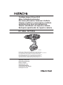
To prevent shorting from occurring, load the battery
in the tool or insert securely the battery cover for
storing until the ventilator is not seen (Fig. 1).
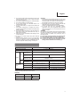
SPECIFICATIONS
POWER TOOL
Model DV14DJL DV18DJL
No-load speed (Low/High) 0 – 350 / 0 – 1400 min
-1
No-load impact rate (Low/High) 0 – 4900 / 0 – 19600 min
-1
Capacity
Drilling
Brick
(Depth 30 mm)
13 mm
Wood
(Thickness 18 mm)
32 mm 38 mm
Metal
(Thickness 1.6 mm)
Steel: 13 mm
Aluminum: 13 mm
Driving
Machine screw 6 mm
Wood screw
8 mm (diameter) × 50 mm (length)
(Requires a pilot hole)
8 mm (diameter) × 75 mm (length)
(Requires a pilot hole)
Rechargeable
battery
2LEGK BSL1415: Li-ion 14.4 V (1.5 Ah 4 celler) BSL1815: Li-ion 18 V (1.5 Ah 5 celler)
2LFGK/2LFRK BSL1425: Li-ion 14.4 V (2.5 Ah 4 celler) BSL1825: Li-ion 18 V (2.5 Ah 5 celler)
NNK/NN
–––– ––––
Weight*
1.6 kg (With BSL1415 attached) 1.7 kg (With BSL1815 attached)
* Weight: According to EPTA-Procedure 01/2003
CHARGER
Model UC18YKSL UC18YFSL
Charging voltage 14.4 V 18 V
Weight 0.35 kg 0.5 kg

English
10
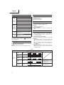
Table 1
Indications of the pilot lamp
Pilot lamp
(red)
Before
charging
Blinks
Lights for 0.5 seconds. Does not light for 0.5
seconds. (o for 0.5 seconds)
While
charging
Lights
Lights continuously
Charging
complete
Blinks
Lights for 0.5 seconds. Does not light for 0.5
seconds. (o for 0.5 seconds)
Overheat
standby
Blinks
Lights for 1 second. Does not light for 0.5
seconds. (o for 0.5 seconds)
Battery overheated.
Unable to charge.
(Charging will commence
when battery cools)
Charging
impossible
Flickers
Lights for 0.1 second. Does not light for 0.1
seconds. (o for 0.1 seconds)
Malfunction in the
battery or the charger
APPLICATIONS
Drilling of brick and concrete block, etc.
Driving and removing of machine screws, wood screws,
tapping screws, etc.
Drilling of various metals.
Drilling of various woods.
BATTERY REMOVAL/INSTALLATION
1. Battery removal
Hold the handle tightly and push the battery latch (2 pcs.)
to remove the battery (See Figs. 1 and 2).
CAUTION
Never short-circuit the battery.
2. Battery installation
Insert the battery while observing its polarities (See
Fig. 2).
CHARGING
Before using the power tool, charge the battery as follows.
1. Connect the charger’s power cord to the receptacle.
When connecting the plug of the charger to
a receptacle, the pilot lamp will blink in red
(At 1-second intervals).
2. Insert the battery into the charger.
Firmly insert the battery into the charger as shown in Fig.
3.
3. Charging
When inserting a battery in the charger, charging will
commence and the pilot lamp will light continuously in
red.
When the battery becomes fully recharged, the
pilot lamp will blink in red (At 1-second intervals).
(See Table 1)
(1) Pilot lamp indication
The indications of the pilot lamp will be as shown in
Table 1, according to the condition of the charger or the
rechargeable battery.
STANDARD ACCESSORIES
DV14DJL
(2LEGK)
DV18DJL
(2LEGK)
ï Plus driver bit (No. 2) ..............................1
î Charger (UC18YKSL) .............................1
í Battery (BSL1415 or BSL1815) .............. 2
ì Plastic case ............................................ 1
ë Battery cover ..........................................1
DV14DJL
(2LFRK)
DV18DJL
(2LFGK)
(2LFRK)
ï Plus driver bit (No. 2) ..............................1
î Charger (UC18YKSL or UC18YFSL) ......1
í Battery (BSL1425 or BSL1825) .............. 2
ì Plastic case ............................................ 1
ë Battery cover ..........................................1
DV18DJL
(NNK)
ï Plus driver bit (No. 2) ..............................1
î Plastic case ............................................ 1
Without charger, battery and battery cover.
DV18DJL
(NN)
ï Plus driver bit (No. 2) ..............................1
Without charger, battery, plastic case and
battery cover.
Standard accessories are subject to change without notice.
The charger and battery supplied are di erent depending on
the set specifi cation.
OPTIONAL ACCESSORIES (sold separately)
Battery
BSL1415S, BSL1415, BSL1425
BSL1815S, BSL1815, BSL1825
Hook
Optional accessories are subject to change without notice.

English
11
(2) Regarding the temperature of the rechargeable battery.
The temperatures for rechargeable batteries are as
shown in Table 2, and batteries that have become hot
should be cooled for a while before being recharged.
Table 2 Recharging ranges of batteries
Rechargeable batteries
Temperatures at which the
battery can be recharged
BSL1415S, BSL1415, BSL1425,
BSL1815S, BSL1815, BSL1825
0°C – 50°C
(3) Regarding recharging time
Depending on the combination of the charger and
batteries, the charging time will become as shown in
Table 3.
Table 3 Charging time (At 20°C)
Charger
Battery
UC18YFSL UC18YKSL
BSL1415S, BSL1815S
Approx. 20 min. Approx. 35 min.
BSL1415, BSL1815 Approx. 22 min. Approx. 40 min.
BSL1425, BSL1825 Approx. 35 min. Approx. 75 min.
NOTE
The charging time may vary according to temperature
and power source voltage.
4. Disconnect the charger’s power cord from the
receptacle
5. Hold the charger fi rmly and pull out the battery
NOTE
Be sure to pull out the battery from the charger after use,
and then keep it.
Regarding electric discharge in case of new batteries,
etc.
As the internal chemical substance of new batteries and
batteries that have not been used for an extended period
is not activated, the electric discharge might be low when
using them the fi rst and second time. This is a temporary
phenomenon, and normal time required for recharging
will be restored by recharging the batteries 2-3 times.
How to make the batteries perform longer.
(1) Recharge the batteries before they become completely
exhausted.
When you feel that the power of the tool becomes
weaker, stop using the tool and recharge its battery. If
you continue to use the tool and exhaust the electric
current, the battery may be damaged and its life will
become shorter.
(2) Avoid recharging at high temperatures.
A rechargeable battery will be hot immediately after use.
If such a battery is recharged immediately after use, its
internal chemical substance will deteriorate, and the
battery life will be shortened. Leave the battery and
recharge it after it has cooled for a while.
CAUTION
If the battery is charged while it is heated because it has
been left for a long time in a location subject to direct
sunlight or because the battery has just been used, the
pilot lamp of the charger lights for 1 second, does not
light for 0.5 seconds (o for 0.5 seconds). In such a case,
fi rst let the battery cool, then start charging.
When the pilot lamp fl ickers (at 0.2-second intervals),
check for and take out any foreign objects in the charger’s
battery connector. If there are no foreign objects, it is
probable that the battery or charger is malfunctioning.
Take it to your authorized Service Center.
Since the built-in microcomputer takes about 3 seconds
to confi rm that the battery being charged with UC18YKSL
or UC18YFSL are taken out, wait for a minimum of 3
seconds before reinserting it to continue charging. If the
battery is reinserted within 3 seconds, the battery may
not be properly charged.
PRIOR TO OPERATION
Setting up and checking the work environment
Check if the work environment is suitable by following the
precautions.
HOW TO USE
1. Confi rm the clutch dial position (See Fig. 4)
The three modes of screwdriver, drill and impact drill can
be switched by the position of the clutch dial in this unit.
(1) When using this unit as a screwdriver, line up the one of
the numbers “1, 3, 5 ... 22” on the clutch dial, or the dots,
with the triangle mark on the outer body.
(2) When using this unit as a drill, align the clutch dial drill
mark “ ” with the triangle mark on the outer body.
(3) When using this unit as an impact drill, align the clutch
dial hammer mark “ ” with the triangle mark on the outer
body.
CAUTION
The clutch dial cannot be set between the numerals “1, 3,
5 ... 22” or the dots.
Do not use with the clutch dial numeral between “22”
and the line at the middle of the drill mark. Doing so may
cause damage (See Fig. 5).
2. Tightening torque adjustment
(1) Tightening torque
Tightening torque should correspond in its intensity to
the screw diameter. When too strong torque is used,
the screw head may be broken or be injured. Be sure
to adjust the clutch dial position according to the screw
diameter.
(2) Tightening torque indication
The tightening torque di ers depending on the type of
screw and the material being tightened.
The unit indicates the tightening torque with the numbers
“1, 3, 5 ... 22” on the clutch dial, and a dots. The tightening
toque at position “1” is the weakest and the torque is
strongest at the highest number (See Fig. 4).
(3) Adjusting the tightening torque
Rotate the clutch dial and line up the numbers “1, 3, 5 ...
22” on the clutch dial, or the dots, with the triangle mark
on the outer body. Adjust the clutch dial in the weak or the
strong torque direction according to the torque you need.
CAUTION
The motor rotation may be locked to cease while the unit
is used as drill. While operating the driver drill, take care
not to lock the motor.
Too long hammering may cause the screw broken due to
excessive tightening.
3. Rotation to Impact changeover (See Fig. 4)
The “Rotation (Rotation only)” and “Impact (Impact +
Rotation)” can be switched by aligning the drill mark “ ”
or the hammer mark “ ” with the triangle mark on the
outer body.

English
12
When setting the shift knob to “HIGH” (high speed) and
the position of the clutch dial is between “15” and “22”, it
may happen that the clutch does not engaged and that
the motor is locked. In such a case, please set the shift
knob to “LOW” (low speed).
If the motor is locked, immediately turn the power o . If
the motor is locked for a while, the motor or battery may
be burnt.
To extend the lifetime, the lithium-ion battery equips with
the protection function to stop the output.Therefore, if the
tool is overloaded, the motor may stop. However, this is
not the trouble but the result of protection function. In this
case, release the switch of tool and eliminate the causes
of overloading.
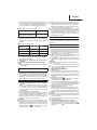
5. The scope and suggestions for uses
The usable scope for various types of work based on the
mechanical structure of this unit is shown in Table 4.
To make holes in the metal, wood or plastic, switch to
“Rotation (Rotation only)”.
To make holes in bricks or concrete blocks, switch to
“Impact (Impact + Rotation)”.
CAUTION
If an operation which is normally performed at the
“Rotation” setting is performed at “Impact” setting, the
e ect of making holes does not only increase but it may
also damage the bit or other parts.
If it is hard to turn the clutch dial to hammer mark
“ ” position, turn the chuck slightly in either direction
and then turn the clutch dial to hammer mark “ ” position
again.
4. Change rotation speed
Operate the shift knob to change the rotational speed.
Move the shift knob in the direction of the arrow (See
Figs. 6 and 7).
When the shift knob is set to “LOW”, the drill rotates at a
low speed. When set to “HIGH”, the drill rotates at a high
speed.
CAUTION
When changing the rotational speed with the shift knob,
confi rm that the switch is o .
Changing the speed while the motor is rotating will
damage the gears.
Table 4
Work Clutch dial position Suggestions
Drilling
Brick
Use for drilling purpose.
Wood
Steel
Aluminum
Driving
Machine screw 1 – 22 Use the bit or socket matching the screw diameter.
Wood screw
1 –
Use after drilling a pilot hole.
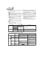
6. How to select tightening torque and rotational speed
Table 5
Use
Clutch Dial
Position
Rotating speed selection (Position of the shift knob)
LOW (Low speed) HIGH (High speed)
Driving
Machine screw 1 – 22
For 4 mm or smaller diameter
screws.
For 6 mm or smaller diameter
screws.
Wood screw 1 –
For 8 mm or smaller nominal
diameter screws.
For 4.8 mm or smaller nominal
diameter screws.
Drilling
Brick
For 13 mm or smaller diameters.
For 8 mm or smaller diameters.
(DV14DJL)
For 10 mm or smaller diameters.
(DV18DJL)
Wood
For 32 mm or smaller diameters.
(DV14DJL)
For 18 mm or smaller diameters.
(DV14DJL)
For 38 mm or smaller diameters.
(DV18DJL)
For 22 mm or smaller diameters.
(DV18DJL)
Metal
For drilling with a metal working
drill bit.

English
13
CAUTION
The selection examples shown in Table 5 should be
considered as general standard. As di erent types of
tightening screws and di erent materials to be tightened
are used in actual works proper adjustments are naturally
necessary.
When using the driver drill with a machine screw at HIGH
(high speed), a screw may damage or a bit may loose
due to the tightning torque is too strong. Use the driver
drill at LOW (low speed) when using a machine screw.
NOTE
The use of the battery in a cold condition (below 0 degree
Centigrade) can sometimes result in the weakened
tightening torque and reduced amount of work. This,
however, is a temporary phenomenon, and returns to
normal when the battery warms up.
7. Mounting and dismounting of the bit
(1) After inserting a driver bit, etc. into the keyless drill chuck,
fi rmly tighten the sleeve by turning it toward the right (in
the clockwise direction as viewed from the front) (See
Fig. 8).
If the sleeve becomes loose during operation, tighten it
further. The tightening force becomes stronger when the
sleeve is tightened additionally.
(2) Dismounting the bit
Loosen the sleeve by turning it toward the left (in the
counter-clockwise direction as viewed from the front)
(See Fig. 8).
CAUTION
When it is no longer possible to loosen the sleeve, use a
vise or similar instrument to secure the bit. Set the clutch
mode between 1 and 11 and then turn the sleeve to the
loose side (left side) while operating the clutch. It should
be easy now to loosen the sleeve.
8. Confi rm that the battery is mounted correctly
9. Check the rotational direction
The bit rotates clockwise (viewed from the rear side) by
pushing the R-side of the selector button.
The L-side of the selector button is pushed to turn the bit
counterclockwise (See Fig. 9) (The
Ô
and
Î
marks are
provided on the body).
CAUTION
Always use this unit with clockwise rotation, when using it
as an impact drill.
10. Switch operation
When the trigger switch is depressed, the tool rotates.
When the trigger is released, the tool stops.
The rotational speed of the drill can be controlled by
varying the amount that the trigger switch is pulled.
Speed is low when the trigger switch is pulled slightly and
increases as the trigger switch is pulled more.
NOTE
A buzzing noise is produced when the motor is about to
rotate; This is only a noise, not a machine failure.
11. For drilling into brick
Excessive pressing force never increases drilling speed.
It will not only damage the drill tip or reduce working
e ciency, but could also shorten the service life of drill
bit. Operate the driver drill within 10-15 kg pressing force
while drilling into brick.
12. Using the light
Pull the trigger switch to light up the light. The light keeps
on lighting while the trigger switch is being pulled. The
light goes out after releasing the trigger switch. (Fig. 10)
(The light automatically goes out 10 seconds after
releasing the trigger switch.)
CAUTION
Do not expose directly your eye to the light by looking into
the light.
If your eye is continuously exposed to the light, your eye
will be hurt.
13. Using the hook (sold separately)
The hook is used to hang up the power tool to your waist
belt while working.
CAUTION
When using the hook, hang up the power tool fi rmly not to
drop accidentally.
If the power tool is dropped, it may lead to an accident.
When carrying the power tool with hooked to your waist
belt, do not fi t any bit to the tip of power tool. If the sharp
bit such as drill is fi tted to the power tool when carrying it
with hooked to your waist belt, you will be injured.
Install securely the hook. Unless the hook is securely
installed, it may cause an injury while using.
(1) Placing the hook and tightening the screws.
Install securely the hook in the groove of power tool and
tighten the screws to fi x the hook fi rmly.(Fig. 11)
(2) Removing the hook.
Remove the screws fi xing the hook with Philips screw
driver. (Fig. 12)
CAUTION
Only Hitachi STANDARD ACCESSORIES phillips bit
(No. 2 × 65L; Code No. 983006) may be used. Do not
use other bits since they may come loose.
MAINTENANCE AND INSPECTION
1. Inspecting the tool
Since use of as dull tool will degrade e ciency and cause
possible motor malfunction, sharpen or replace the tool
as soon as abrasion is noted.
2. Inspecting the mounting screws
Regularly inspect all mounting screws and ensure that
they are properly tightened. Should any of the screws be
loose, retighten them immediately. Failure to do so could
result in serious hazard.
3. Maintenance of the motor
The motor unit winding is the very “heart” of the power
tool.
Exercise due care to ensure the winding does not
become damaged and/or wet with oil or water.
4. Cleaning on the outside
When the driver drill is stained, wipe with a soft dry cloth
or a cloth moistened with soapy water. Do not use chloric
solvents, gasoline or paint thinner, for they melt plastics.
5. Storage
Store the driver drill in a place in which the temperature is
less than 40°C and out of reach of children.
NOTE
Make sure that the battery is fully charged when stored
for a long period (3 months or more). The battery with
smaller capacity may not be able to be charged when
used, if stored for a long period.
NOTE
Storing Lithium-ion Batteries
Make sure the lithium-ion batteries have been fully
charged before storing them.
Prolonged storage of batteries with a low charge may
result in performance deterioration, signifi cantly reducing
battery usage time or rendering the batteries incapable of
holding a charge.

English
14
However, signifi cantly reduced battery usage time may
be recovered by repeatedly charging and using the
batteries two to fi ve times.
If the battery usage time is extremely short despite
repeated charging and use, consider the batteries dead
and purchase new batteries.
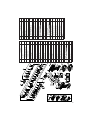
6. Service parts list
CAUTION
Repair, modifi cation and inspection of Hitachi Power
Tools must be carried out by a Hitachi Authorized Service
Center.
This Parts List will be helpful if presented with the tool to
the Hitachi Authorized Service Center when requesting
repair or other maintenance.
In the operation and maintenance of power tools, the
safety regulations and standards prescribed in each
country must be observed.
MODIFICATIONS
Hitachi Power Tools are constantly being improved
and modifi ed to incorporate the latest technological
advancements.
Accordingly, some parts may be changed without prior
notice.
Important notice on the batteries for the Hitachi
cordless power tools
Please always use one of our designated genuine
batteries. We cannot guarantee the safety and
performance of our cordless power tool when used with
batteries other than these designated by us, or when
the battery is disassembled and modifi ed (such as
disassembly and replacement of cells or other internal
parts).
GUARANTEE
We guarantee Hitachi Power Tools in accordance with
statutory/country specifi c regulation. This guarantee does
not cover defects or damage due to misuse, abuse, or normal
wear and tear. In case of complaint, please send the Power
Tool, undismantled, with the GUARANTEE CERTIFICATE
found at the end of this Handling instruction, to a Hitachi
Authorized Service Center.
NOTE
Due to HITACHI’s continuing program of research and
development, the specifi cations herein are subject to change
without prior notice.
Information concerning airborne noise and vibration
The measured values were determined according to
EN60745 and declared in accordance with ISO 4871.
Measured A-weighted sound power level: 96 dB (A)
Measured A-weighted sound pressure level: 85 dB (A)
Uncertainty KpA: 3 dB (A).
Wear hearing protection.
Vibration total values (triax vector sum) determined according
to EN60745.
Impact drilling into concrete:
Vibration emission value ah, ID = 11.1 m/s
2
Uncertainty K = 1.5 m/s
2
The declared vibration total value has been measured in
accordance with a standard test method and may be used
for comparing one tool with another.
It may also be used in a preliminary assessment of
exposure.
WARNING
The vibration emission value during actual use of the
power tool can di er from the declared value depending
on the ways in which the tool is used.
Identify safety measures to protect the operator that
are based on an estimation of exposure in the actual
conditions of use (taking account of all parts of the
operating cycle such as the times when the tool is
switched o and when it is running idle in addition to the
trigger time).

69
48
22
21
501
502
1
2
4
5
6
7
8
9
10
11
12
13
14
15
16
17
23
24
25
26
27
31
3
32
33
28
29
30
34
36
503
504
30
42
46
43
44
41
48
41
47
35
39
40
38
18
19
20
502
37
45
49
37
44
35
45
49
3835
44
42
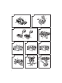
BSL1415
BSL1425
BSL1815
BSL1825
UC18YKSL
UC18YFSL
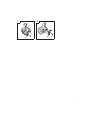
Item
No.
Part NameQ’TY
1
SPECIAL SCREW (LEFT HAND)
M6X23
1
2
DRILL CHUCK 13VLRV-N
(W/O CHUCK WRENCH)
1
3
GEAR BOX ASS'Y
(INCLUD.4-34)
1
4CLUTCH DIAL1
5CLICK SPRING1
6O-RING1
7SPINDLE1
8SPRING (C)1
9RATCHET (B)1
10WASHER (A)1
11NUT1
12WASHER1
13SLIP BLOCK2
14STOPPER SPRING2
15FRONT CASE1
16SPRING (A)4
17STEEL BALL D5 4
18LOCK RING1
19NEEDLE ROLLER SET (4 PCS.)4
20SLEEVE1
21RING GEAR1
22CARRIER1
23PLANET GEAR (C) SET (3 PCS.)3
24WASHER (A)1
25REAR CASE1
26SCREW SET D3X12 (4 PCS.)4
27SHIFT ARM1
28SLIDE RING GEAR1
29PINION (C) 1
30PLANET GEAR (A) SET (6 PCS.)6
Item
No.
Part NameQ’TY
31PINION (B)1
32FIRST RING GEAR1
33WASHER (B)1
34MOTOR SPACER1
35MOTOR DC 14.4V1
36
MACHINE SCREW
(W/SP.WASHER) M4X6
2
37INTERNAL WIRE FERRITE SET1
38INTERNAL WIRE (BLACK) 110L1
39HOUSING (A).(B) SET1
40SHIFT KNOB1
41LOCK NUT M4 (BLACK)2
42INTERNAL WIRE (RED) 140L1
43PUSHING BUTTON1
44SWITCH TERMINAL SET1
45SUPPORT (D)1
46
TAPPING SCREW
(W/FLANGE) D3X16 (BLACK)
9
47NAME PLATE1
48BATTERY (INCLUD.504) 2
49
WIRING SET
(INCLUD.35,38,42,44)
1
49
WIRING SET
(INCLUD.35,37,44,45)
1
501+ DRIVER BIT NO.2 65L1
502
CHARGER
(UC18YKSL/UC18YFSL)
1
503CASE1
504BATTERY COVER1

70

71
English Nederlands
GUARANTEE CERTIFICATE
ï Model No.
î Serial No.
í Date of Purchase
ì Customer Name and Address
ë Dealer Name and Address
(Please stamp dealer name and address)
GARANTIEBEWIJS
ï Modelnummer
î Serienummer
í Datum van aankoop
ì Naam en adres van de gebruiker
ë Naam en adres van de handelaar
(Stempel a.u.b. naam en adres vande de
handelaar)
Deutsch Español
GARANTIESCHEIN
ï Modell-Nr.
î Serien-Nr.
í Kaufdaturn
ì Name und Anschrift des Kunden
ë Name und Anschrift des Händlers
(Bitte mit Namen und Anschrift des Handlers
abstempeln)
CERTIFICADO DE GARANTÍA
ï Número de modelo
î Número de serie
í Fecha de adquisición
ì Nombre y dirección del cliente
ë Nombre y dirección del distribudor
(Se ruega poner el sello del distribudor con su
nombre y dirección)
Français Português
CERTIFICAT DE GARANTIE
ï No. de modèle
î No de série
í Date d achat
ì Nom et adresse du client
ë Nom et adresse du revendeur
(Cachet portant le nom et l adresse du
revendeur)
CERTIFICADO DE GARANTIA
ï Número do modelo
î Número do série
í Data de compra
ì Nome e morada do cliente
ë Nome e morada do distribuidor
(Por favor, carímbe o nome e morada do
distribuidor)
Italiano
CERTIFICATO DI GARANZIA
ï Modello
î N° di serie
í Data di acquisto
ì Nome e indirizzo dell acquirente
ë Nome e indirizzo del rivenditore
(Si prega di apporre il timbro con questi dati)

72
ï
î
í
ì
ë

73
Hitachi Power Tools Europe GmbH
Siemensring 34, 47877 willich, Germany
Tel: +49 2154 49930
Fax: +49 2154 499350
URL: http://www.hitachi-powertools.de
Hitachi Power Tools Netherlands B. V.
Brabanthaven 11, 3433 PJ Nieuwegein, The Netherlands
Tel: +31 30 6084040
Fax: +31 30 6067266
URL: http://www.hitachi-powertools.nl
Hitachi Power Tools (U. K.) Ltd.
Precedent Drive, Rooksley, Milton Keynes, MK 13, 8PJ, United Kingdom
Tel: +44 1908 660663
Fax: +44 1908 606642
URL: http://www.hitachi-powertools.co.uk
Hitachi Power Tools France S. A. S.
Parc de l’Eglantier 22, rue des Cerisiers, Lisses-C.E. 1541,
91015 EVRY CEDEX, France
Tel: +33 1 69474949
Fax: +33 1 60861416
URL: http://www.hitachi-powertools.fr
Hitachi Power Tools Belgium N.V. / S.A.
Koningin Astridlaan 51, B-1780 Wemmel, Belgium
Tel: +32 2 460 1720
Fax: +32 2 460 2542
URL http://www.hitachi-powertools.be
Hitachi Fercad Power Tools Italia S.p.A
Via Retrone 49, 36077, Altavilla Vicentina (VI), Italy
Tel: +39 0444 548111
Fax: +39 0444 548110
URL: http://www.hitachi-powertools.it
Hitachi Power Tools lberica, S.A.
Puigbarral, 26-28 Pol. Ind. Can Petit 08227
TERRSSA(Barcelona) Spain
Tel: +34 93 735 6722
Fax: +34 93 735 7442
URL: http://www.hitachi-powertools.es
Hitachi Power Tools Österreich GmbH
Str. 7, Objekt 58/A6, Industriezentrum NÖ –Süd 2355
Wiener Neudorf, Austria
Tel: +43 2236 64673/5
Fax: +43 2236 63373
URL: http://www.hitachi-powertools.at/

74
La pagina si sta caricando...
La pagina si sta caricando...
-
 1
1
-
 2
2
-
 3
3
-
 4
4
-
 5
5
-
 6
6
-
 7
7
-
 8
8
-
 9
9
-
 10
10
-
 11
11
-
 12
12
-
 13
13
-
 14
14
-
 15
15
-
 16
16
-
 17
17
-
 18
18
-
 19
19
-
 20
20
-
 21
21
-
 22
22


Hitachi DV 18DJL Handling Instructions Manual
- Categoria
- Utensili elettrici
- Tipo
- Handling Instructions Manual
- Questo manuale è adatto anche per
in altre lingue
- English: Hitachi DV 18DJL
Documenti correlati
-
Hitachi DV 18DJL Handling Instructions Manual
-
Hitachi DS 14 DJ L Manuale del proprietario
-
-
-
-
-
Hitachi d10vc2 Manuale del proprietario
-
-
-
Altri documenti
-
Hikoki WH36DC Manuale utente
-
-
-
-
-
-
Stanley SFMCD710 Manuale utente
-
Hikoki DN18DSL Manuale utente
-
Stanley SFMCD720 Manuale utente
-