Honeywell SM-RI-X, Q75 Istruzioni per l'uso
- Tipo
- Istruzioni per l'uso

Honeywell
730xxxxxx © Elster GmbH | All rights reserved. Subject to modification 1
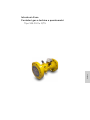
English
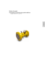
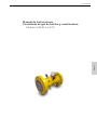
Instruction manual
Turbine gas meters and quantometers
Type SM-RI-X • Q75
Betriebsanleitung
Turbinenradgaszähler und Quantometer
Typ SM-RI-X • Q75
Mode d’emploi
Compteurs de gaz à turbine et quantomètres
Type SM-RI-X • Q75
Manual de instrucciones
Contadores de gas de turbina y cuantómetros
Modelos SM-RI-X • Q75
Istruzioni d’uso
Contatori gas a turbina e quantometri
Tipo SM-RI-X • Q75
Gebruiksaanwijzing
Turbinegasmeters en quantometers
Type SM-RI-X • Q75

Honeywell
2 730xxxxxx © Elster GmbH | All rights reserved. Subject to modification

Honeywell
730xxxxxx © Elster GmbH | All rights reserved. Subject to modification 3
English
Français
Español
Italiano
Nederlands
Deutsch
Instruction manual
Turbine gas meters and quantometers
Type SM-RI-X • Q75
Betriebsanleitung
Turbinenradgaszähler und Quantometer
Typ SM-RI-X • Q75
Mode d’emploi
Compteurs de gaz à turbine et quantomètres
Type SM-RI-X • Q75
Manual de instrucciones
Contadores de gas de turbina y cuantómetros
Modelos SM-RI-X • Q75
Istruzioni d’uso
Contatori gas a turbina e quantometri
Tipo SM-RI-X • Q75
Gebruiksaanwijzing
Turbinegasmeters en quantometers
Type SM-RI-X • Q75

Honeywell
4 730xxxxxx © Elster GmbH | All rights reserved. Subject to modification

Honeywell
73024521c © Elster GmbH | All rights reserved. Subject to modification 5
English
Instruction manual
Turbine gas meters and quantometers
Type SM-RI-X • Q75


Honeywell
73024521c © Elster GmbH | All rights reserved. Subject to modification 7
English
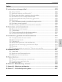
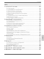
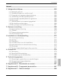
Contents
1. Safety instructions.................................................................................................... 9
1.1 Intended use .............................................................................................................. 10
1.2 Approvals and certifications* ............................................................................ 10
1.3 Copyright and data protection ......................................................................... 11
1.4 Exemption from liability ....................................................................................... 11
1.5 Product liability and guarantee ........................................................................ 12
1.6 Personnel .................................................................................................................... 12
1.7 Intended use and field of application ........................................................... 12
1.8 Legal declarations .................................................................................................. 12
1.9 Recycling and environmental protection .................................................... 13
2. Structure and function ......................................................................................... 14
2.1 Device description .................................................................................................. 15
2.2 Index .............................................................................................................................. 16
2.3. Temperature test points ..................................................................................... 16
2.4 Pressure test points ............................................................................................... 17
3. Installation and commissioning ....................................................................... 18
3.1 Scope of delivery ...................................................................................................... 18
3.2 Storage ......................................................................................................................... 18
3.3 Transport ..................................................................................................................... 18
3.4 Requirements to be met before installation .............................................. 19
3.5 Installation position and flow direction ........................................................ 20
3.6 Installation.................................................................................................................. 21
3.7 Commissioning/Filling with oil ........................................................................ 22
4. Maintenance ............................................................................................................ 23
4.1 Cleaning ...................................................................................................................... 25
4.2 Repair/Removal ....................................................................................................... 25
4.3 Disposal ....................................................................................................................... 25
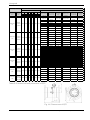
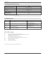
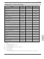
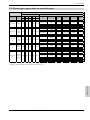
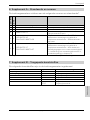
5. Technical data ......................................................................................................... 26
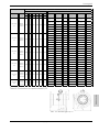
5.1 Dimensions, weights and connections ........................................................ 28
5.2 Ambient conditions ................................................................................................ 31
5.3 Approvals** ................................................................................................................. 31
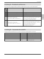
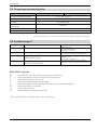
6. Annex A – Standards and Norms ...................................................................... 32
7. Annex B – Plastics used ....................................................................................... 32
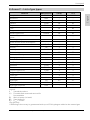
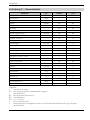
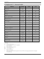
8. Annex C – List of gas types ................................................................................. 33

Honeywell
8 73024521c © Elster GmbH | All rights reserved. Subject to modification
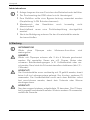
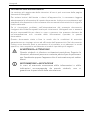
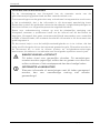
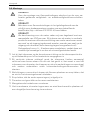
Information on the documentation
The latest version of the operating instructions is available to download from the
Honeywell website.
Please read the information in this document carefully in order to avoid injury to
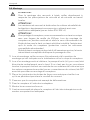
the user or damage to the device. Moreover, currently valid national standards,
safety regulations and accident prevention regulations must be adhered to.
Should you have any problems understanding the contents of this document,
please contact your local Honeywell branch for support. Honeywell cannot
accept any responsibility for damage to property or personal injuries which are a
result of the information in this document not having been understood properly.
This document helps you to set up the operating conditions in such a way that
the safe and efficient use of the device is assured. In addition, this document also
specifies points and safety measures which must be particularly observed and
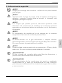
which are indicated using the following symbols:
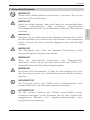
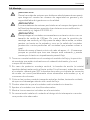
WARNING or CAUTION
This symbol warns of dangerous situations. Failure to follow the
instructions could result in danger to people and the
environment or the meter could suffer damage.
INFORMATION or NOTE
Accurate measurement cannot be ensured if information or
notes with this symbol are ignored.

Honeywell
73024521c © Elster GmbH | All rights reserved. Subject to modification 9
English
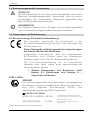
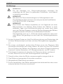
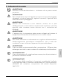
1. Safety instructions
WARNING!
Danger of electrostatic discharge – only use a damp cloth to clean.
WARNING!
If there is danger that the device can be damaged from falling
(pointed, sharp-edged or heavy) objects, the operator must protect
the device.
WARNING!
Exposure to danger which can result from a chemical reaction
between parts of the meter and chemical substances in the vicinity
must be discussed with the manufacturer and the cause must be
eliminated.
WARNING!
The meter must be included in the equipotential bond by
connecting it to the grounded pipeline.
WARNING!
If you wish to add odorants or use solenoid valves, please always fit
them downstream of the meter only. Otherwise, the device may be
damaged.
WARNING!
The gas should not contain suspended particles > 50 µm. In
addition, the gas must be dry. Otherwise, the meter may be
damaged.
INFORMATION!
The flow through the meter must be free of vibrations and
pulsations in order to avoid measuring errors.
INFORMATION!
Compliance with the specified operating and ambient conditions
as indicated on the type label is absolutely essential for safe
operation of the meter and additional equipment.

Honeywell
10 73024521c © Elster GmbH | All rights reserved. Subject to modification
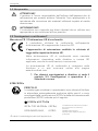
1.1 Intended use
CAUTION!
Responsibility for the use of the meter in terms of suitability,
intended use and the corrosion resistance of the materials to the
medium is solely in the hands of the operator.
INFORMATION!
The manufacturer shall not be liable for damage caused by
improper or inappropriate use.
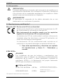
1.2 Approvals and certifications*
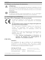
CE marking / EU declaration of conformity
The manufacturer certifies conformity with the EU
declaration of conformity and by attaching the CE marking.
The measuring instrument meets the statutory
requirements of the relevant EU Directives.
Comprehensive information on the applicable EU
Directives and Standards, as well as recognized
certification
s, is contained in the EU declaration of
conformity.
The EU declaration of conformity is included in the delivery
and is also available to download at www.docuthek.com.
See chapter 5.3 Approvals and Annex A –
Standards and Norms, for details of other
approvals and Directives.
ATEX/IECEx
DANGER!
The turbine gas meters and quantometers are suitable for use
in Zone 1 hazardous areas and are approved with the following
certification (IECEx) and manufacturer’s declaration (ATEX):
II 2G Ex h IIC T4 Gb
IECEx TUR 16.0043x (IECEx)
203104000-0411 (ATEX)
TÜV Rheinland Industrieservice GmbH
Am Grauen Stein | 51105 Köln | Germany
DEKRA Certification B.V.
Meander 1051 | 6825 MJ Arnheim | The
Netherlands
* The marking on the device shall be applicable.

Honeywell
73024521c © Elster GmbH | All rights reserved. Subject to modification 11
English
1.3 Copyright and data protection
This document has been created with the greatest possible care. No liability
is assumed for the accuracy, completeness or currency of the contents.
The contents and works produced in this document are subject to copyright.
Contributions by third parties are identified as such. The reproduction,
processing, distribution and any form of use beyond that which is permitted
by copyright require the written authorization of the respective author or the
manufacturer. The manufacturer strives to always respect the copyright of
others or to use his own or licence-free works.
We would like to point out that data transfer via the Internet (e.g. through e-
mail communication) can be subject to breaches in security. It is not
possible to provide complete protection against access by third parties.
1.4 Exemption from liability
The manufacturer shall not be liable for damage of any type caused by the
use of this product, including but not restricted to, direct, indirect or
incidental damage and its consequences.
This exemption from liability does not apply if the manufacturer has acted
intentionally or with gross negligence. In the event that any applicable law
does not allow such restrictions on implied warranties for defects, or the
exclusion or limitation of certain payments for damages, and should such
law apply to you, the above-mentioned exemption from liability, exclusions
or limitations may not apply to you in part or in whole.
For every product purchased, the warranty is valid in accordance with the
corresponding product documentation as well as the conditions of sale and
delivery of the manufacturer.
The manufacturer reserves the right to amend without prior notice the
contents of the documents, including this exemption from liability, in any
form and at any point in time, and for any reason, and shall in no way be liable
for any possible consequences of such amendments.

Honeywell
12 73024521c © Elster GmbH | All rights reserved. Subject to modification
1.5 Product liability and guarantee
The responsibility as to whether the measuring instrument is suitable for the
intended use is that of the operator. The manufacturer cannot accept any
liability for the consequences of misuse by the operator. Improper
installation or operation of the measuring instruments (systems) will render
the warranty void. Furthermore, the relevant “General Terms and Conditions”
which form the basis of the purchase contract also apply.
1.6 Personnel
This manual is aimed at staff who have adequate specialist and technical
knowledge (in Germany, for instance, in accordance with DVGW Codes of
Practice 492 and 495 or comparable technical regulations) on the basis of
their training and experience in the sector of energy and gas distribution.
1.7 Intended use and field of application
Model series SM-RI-X is designed for calibratable volumetric metering.
Model series Q75 is designed for non-calibratable volumetric metering.
All devices are suitable for metering the following media:
Flammable gases: natural gas/town gas/propane/butane
Non-flammable gases: air/nitrogen/inert gases
Other areas of application or media, see Annex C – List of gas types or
on request
This product is not intended for
metering aggressive gases, e.g. biogas or sewage gases, oxygen or
acetylene.
1.8 Legal declarations
The metrological conformity assessment is based on the regulations of
the country concerned, in which the measuring instrument will be used.
The period of validity of calibration is based on the regulations of the
country concerned, in which the measuring instrument will be used.

Honeywell
73024521c © Elster GmbH | All rights reserved. Subject to modification 13
English
1.9 Recycling and environmental protection
Honeywell has designed the transport packaging of the measuring
instrument to be environmentally friendly. Packaging materials are always
selected consistently with a view to recycling. The cardboard items used
constitute secondary raw materials for the paperboard and paper industry.
The Instapak® foam packaging items can be recycled and reused in most
countries. Plastic sheeting and strips/bands are also made of recyclable
plastic. At Honeywell, subsequent recycling and disposal are already
elements of the product development process. When selecting the materials,
we allow for reusability of the materials, suitability of materials and
subassemblies for dismantling and separation, and the risks of
environmental pollution and health risks when recycling and dumping on
landfill sites. The measuring instruments mainly consist of metallic materials
which can be melted down again in steelworks and metallurgical plants and
which can thus be reused a virtually unlimited number of times. The plastics
used are listed in Annex B to ensure that the materials can be sorted and
separated for the purposes of subsequent recycling.
Like all mineral oils (e.g. for motor vehicles), the oil supplied with the device
must be disposed of in an environmentally sound way.

Honeywell
14 73024521c © Elster GmbH | All rights reserved. Subject to modification
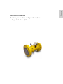
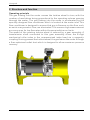
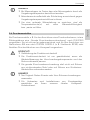
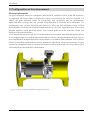
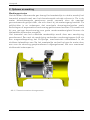
2. Structure and function
Operating principle
The gas flowing into the meter causes the turbine wheel to turn, with the
number of revolutions being proportional to the operating volume passing
through the meter. The gas flowing into the meter is accelerated by the
specially designed flow conditioner which is located at the meter inlet. This
flow conditioner is designed to ensure that any influences on the flow, such
as swirls or asymmetric flow, are eliminated. This ensures high measurement
accuracy even for low flow rates within the permissible error limits.
The speed of the rotating turbine wheel is reduced by a gear assembly. A
transmission shaft connected to this gear assembly drives the 8-digit
mechanical roller index in the unpressurized index head via a magnetic
coupling. Having passed the turbine wheel, the gas leaves the meter through
a flow-optimized outlet duct which is designed to allow maximum pressure
recovery.

Honeywell
73024521c © Elster GmbH | All rights reserved. Subject to modification 15
English
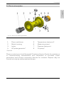
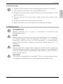
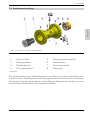
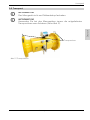
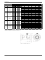
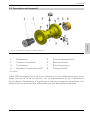
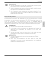
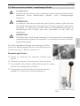
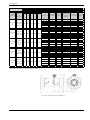
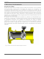
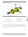
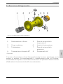
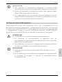
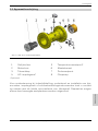
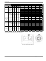
2.1 Device description
1 Flow conditioner 5 Temperature test point*
2 Meter housing 6 Measuring insert
3 Index 7 Pressure test point
4 HF pulse generator* 8 Oil pump*
* Optional
Please contact your local Honeywell Customer Service Centre for assistance
in commissioning, maintenance and installation of encoders, pulse
generators and volume conversion devices for instance. Repairs may be
carried out only by authorized workshops.
Fig. 2 | SM-RI-X turbine gas meter

Honeywell
16 73024521c © Elster GmbH | All rights reserved. Subject to modification
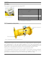
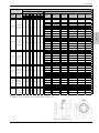
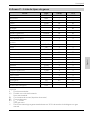
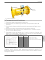
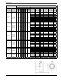
2.2 Index
The meter is equipped with the index MI-2.
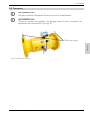
2.3. Temperature test points
Temperature sensors can be inserted into a thermowell for measuring the
gas temperature in the gas meter housing. Up to two thermowells are
available for this on turbine meters SM-RI as an option (depending on the
meter size). The maximum diameter of the thermowell can be 10 mm
There are no temperature test points on quantometers Q75.
If no temperature test points are provided in the meter housing, external
temperature measurements must be taken in the pipe downstream of the
gas meter at a distance of up to 3 x DN, but max. 600 mm away.
Property:
MI-2
Mechanical roller index, 8-digit
•
Index, can be turned through 355°
•
Optional: Protection class IP67
•
45° reading
•
Vertical reading
•
Connection for external pulse generator IN-
Sxx/IN-Wxx
•
S1xR internal reed contact pulse generator
-
Optional: desiccant cartridge
•
Optional: ENCODER
•
Fig. 3 | Index MI-2
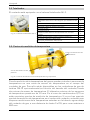
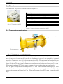
Fig. 4 | Temperature and pressure test points
Temperature test point
Pressure test point
Table 1 | Properties of index MI-2

Honeywell
73024521c © Elster GmbH | All rights reserved. Subject to modification 17
English
NOTE!
In outdoor measuring systems, the result of measurement may
be influenced by the ambient temperature.
Insulate measuring elements outside the pipe adequately to
prevent ambient temperature influences.
Fill the thermowell(s) with a heat-conductive fluid or paste to
achieve optimum thermal conduction.
2.4 Pressure test points
A straight male coupling which complies with DIN 2353 is provided on the
meter housing to act as a pressure test point, for example to connect a
pressure sensor. It is marked pm/pr and is designed for connecting Ø 6 mm
steel tubes to DIN EN 10305-1 (e.g. steel grade E235) or flexible pressure
tubes from Honeywell.
CAUTION!
Danger to functional safety!
Functional safety and reliability are ensured only if the material
combination of the union component and the pipe are
intermatched.
The straight male coupling must not be connected to pipes
made of stainless steel or pipes made of non-ferrous materials.
NOTE!
Only use original Parker-Ermeto or Voss pipe unions.
We recommend that you contact our local Honeywell Customer
Service Centre for conversion work and when installing
additional devices.

Honeywell
18 73024521c © Elster GmbH | All rights reserved. Subject to modification
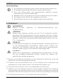
3. Installation and commissioning
INFORMATION!
Check the packing list to ensure that you have received your
complete order. Check the type labels to ensure that the device
supplied is the one you ordered.
INFORMATION!
Check the packaging carefully for signs of damage or signs that
the device has been handled incorrectly. Report any damage to the
forwarding agent and to the local representative of the
manufacturer.
INFORMATION!
The installation material and tools are not supplied with the device.
Use installation material and tools which comply with current
health and safety regulations.
3.1 Scope of delivery
Ordered measuring instrument
Instruction manual
Product documentation
Oil – Klüber Isoflex PDP 38 (for meters lubricated with oil)
Optional accessories depending on the purchase order
Optional: calibration certificate
3.2 Storage
Store the device in a dry and dust-free location.
Avoid constant direct sunlight.
Store the device in its original packaging.
Storage temperature: -25 to +70°C / -13 to +158°F.
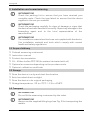
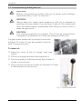
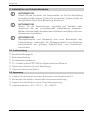
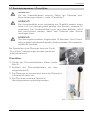
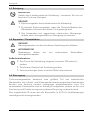
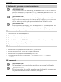
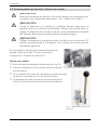
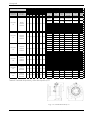
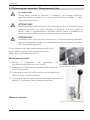
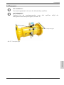
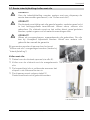
3.3 Transport
INFORMATION!
Do not lift the measuring instrument by the index.
INFORMATION!
Always use the supplied lifting lugs (see Fig. 5) for transporting the
meters.

Honeywell
73024521c © Elster GmbH | All rights reserved. Subject to modification 19
English
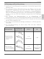
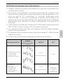
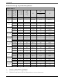
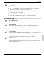
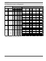
3.4 Requirements to be met before installation
Remove sealing caps and foils.
Check the meter and accessories for signs of transport damage.
Check that the turbine moves easily by generating a gentle air current.
Ensure that you have all the tools you require available.
Check that all the accessories are present (e.g. plug connectors, oil for
initial filling).
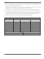
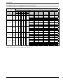
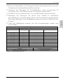
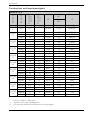
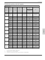
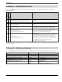
Seals which are suitable for your operating medium (see Table 3 for
examples). Please also check whether you must comply with other
standards, e.g. DIN EN 1591, Parts 1 – 4.
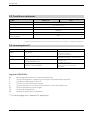
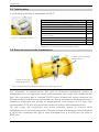
Table 3 | Suitable seals and gaskets
Smallest internal diameter of the seal as per Table 3. The seal must be
installed concentrically with the flange and must not project into the flow.
DN
d1 [mm]
The following seals and
gaskets, among others, are
suitable:
- flat seals
- spiral-wound gaskets
- grooved seals and gaskets
50
60
80
90
100
120
150
170
200
225
250
260
300
310
400
390
500
480
600
570
Lifting lugs
Fig. 5 | Lifting lugs

Honeywell
20 73024521c © Elster GmbH | All rights reserved. Subject to modification
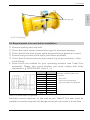
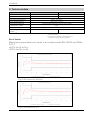
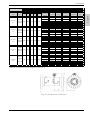
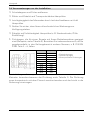
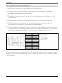
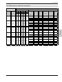
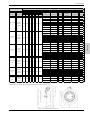
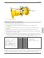
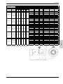
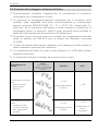
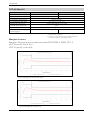
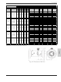
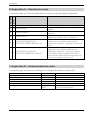
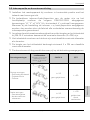
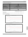
3.5 Installation position and flow direction
Install the meter ideally in a horizontal position with the index at the top.
The permitted installation/operating positions of the meter are specified
on the main plate in accordance with the designations “H”, “V” or “H/V”
(H = horizontal, V = vertical) to DIN EN 12261. If you have specified the
installation or operating position when ordering, all attachments will have
been fitted in accordance with the installation position ex-works.
The minimum length of the inlet section for SM-RI-X must be at least
twice the nominal diameter (2 x DN) for reasons relating to measurement
accuracy.
The inlet section must be designed as a straight pipe section with the
same nominal diameter as the meter.
The length of the outlet section is at least 1 x DN of the same nominal
diameter.
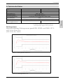
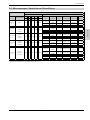
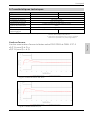
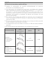
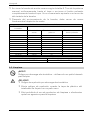
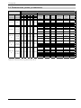
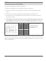
The direction of flow is indicated by an arrow on the housing:
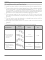
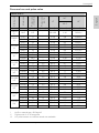
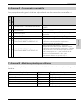
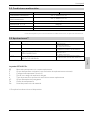
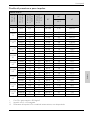
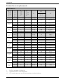
Flow disturbances
Typical inlet
sections
Pipe sections installed at a
distance of 2D upstream
of the meter inlet
SM-RI-X Q75
Minor disturbances
- single manifolds
- twin manifolds
- diffusers
L ≥ 2D
No flow conditioner
L ≥ 5D
Major disturbances
- pressure regulators
for gas
- other restrictors
L ≥ 2D
No flow conditioner
L ≥ 5D
Flow conditioner
recommended
Table 4 | Inlet sections
La pagina sta caricando ...
La pagina sta caricando ...
La pagina sta caricando ...
La pagina sta caricando ...
La pagina sta caricando ...
La pagina sta caricando ...
La pagina sta caricando ...
La pagina sta caricando ...
La pagina sta caricando ...
La pagina sta caricando ...
La pagina sta caricando ...
La pagina sta caricando ...
La pagina sta caricando ...
La pagina sta caricando ...
La pagina sta caricando ...
La pagina sta caricando ...
La pagina sta caricando ...
La pagina sta caricando ...
La pagina sta caricando ...
La pagina sta caricando ...
La pagina sta caricando ...
La pagina sta caricando ...
La pagina sta caricando ...
La pagina sta caricando ...
La pagina sta caricando ...
La pagina sta caricando ...
La pagina sta caricando ...
La pagina sta caricando ...
La pagina sta caricando ...
La pagina sta caricando ...
La pagina sta caricando ...
La pagina sta caricando ...
La pagina sta caricando ...
La pagina sta caricando ...
La pagina sta caricando ...
La pagina sta caricando ...
La pagina sta caricando ...
La pagina sta caricando ...
La pagina sta caricando ...
La pagina sta caricando ...
La pagina sta caricando ...
La pagina sta caricando ...
La pagina sta caricando ...
La pagina sta caricando ...
La pagina sta caricando ...
La pagina sta caricando ...
La pagina sta caricando ...
La pagina sta caricando ...
La pagina sta caricando ...
La pagina sta caricando ...
La pagina sta caricando ...
La pagina sta caricando ...
La pagina sta caricando ...
La pagina sta caricando ...
La pagina sta caricando ...
La pagina sta caricando ...
La pagina sta caricando ...
La pagina sta caricando ...
La pagina sta caricando ...
La pagina sta caricando ...
La pagina sta caricando ...
La pagina sta caricando ...
La pagina sta caricando ...
La pagina sta caricando ...
La pagina sta caricando ...
La pagina sta caricando ...
La pagina sta caricando ...
La pagina sta caricando ...
La pagina sta caricando ...
La pagina sta caricando ...
La pagina sta caricando ...
La pagina sta caricando ...
La pagina sta caricando ...
La pagina sta caricando ...
La pagina sta caricando ...
La pagina sta caricando ...
La pagina sta caricando ...
La pagina sta caricando ...
La pagina sta caricando ...
La pagina sta caricando ...
La pagina sta caricando ...
La pagina sta caricando ...
La pagina sta caricando ...
La pagina sta caricando ...
La pagina sta caricando ...
La pagina sta caricando ...
La pagina sta caricando ...
La pagina sta caricando ...
La pagina sta caricando ...
La pagina sta caricando ...
La pagina sta caricando ...
La pagina sta caricando ...
La pagina sta caricando ...
La pagina sta caricando ...
La pagina sta caricando ...
La pagina sta caricando ...
La pagina sta caricando ...
La pagina sta caricando ...
La pagina sta caricando ...
La pagina sta caricando ...
La pagina sta caricando ...
La pagina sta caricando ...
La pagina sta caricando ...
La pagina sta caricando ...
La pagina sta caricando ...
La pagina sta caricando ...
La pagina sta caricando ...
La pagina sta caricando ...
La pagina sta caricando ...
La pagina sta caricando ...
La pagina sta caricando ...
La pagina sta caricando ...
La pagina sta caricando ...
La pagina sta caricando ...
La pagina sta caricando ...
La pagina sta caricando ...
La pagina sta caricando ...
La pagina sta caricando ...
La pagina sta caricando ...
La pagina sta caricando ...
La pagina sta caricando ...
La pagina sta caricando ...
La pagina sta caricando ...
La pagina sta caricando ...
La pagina sta caricando ...
La pagina sta caricando ...
La pagina sta caricando ...
La pagina sta caricando ...
La pagina sta caricando ...
La pagina sta caricando ...
La pagina sta caricando ...
La pagina sta caricando ...
La pagina sta caricando ...
La pagina sta caricando ...
La pagina sta caricando ...
La pagina sta caricando ...
La pagina sta caricando ...
La pagina sta caricando ...
La pagina sta caricando ...
La pagina sta caricando ...
La pagina sta caricando ...
La pagina sta caricando ...
La pagina sta caricando ...
La pagina sta caricando ...
La pagina sta caricando ...
La pagina sta caricando ...
La pagina sta caricando ...
La pagina sta caricando ...
La pagina sta caricando ...
La pagina sta caricando ...
La pagina sta caricando ...
La pagina sta caricando ...
La pagina sta caricando ...
La pagina sta caricando ...
La pagina sta caricando ...
La pagina sta caricando ...
La pagina sta caricando ...
La pagina sta caricando ...
La pagina sta caricando ...
La pagina sta caricando ...
La pagina sta caricando ...
La pagina sta caricando ...
La pagina sta caricando ...
La pagina sta caricando ...
La pagina sta caricando ...
La pagina sta caricando ...
La pagina sta caricando ...
La pagina sta caricando ...
La pagina sta caricando ...
La pagina sta caricando ...
La pagina sta caricando ...
La pagina sta caricando ...
-
 1
1
-
 2
2
-
 3
3
-
 4
4
-
 5
5
-
 6
6
-
 7
7
-
 8
8
-
 9
9
-
 10
10
-
 11
11
-
 12
12
-
 13
13
-
 14
14
-
 15
15
-
 16
16
-
 17
17
-
 18
18
-
 19
19
-
 20
20
-
 21
21
-
 22
22
-
 23
23
-
 24
24
-
 25
25
-
 26
26
-
 27
27
-
 28
28
-
 29
29
-
 30
30
-
 31
31
-
 32
32
-
 33
33
-
 34
34
-
 35
35
-
 36
36
-
 37
37
-
 38
38
-
 39
39
-
 40
40
-
 41
41
-
 42
42
-
 43
43
-
 44
44
-
 45
45
-
 46
46
-
 47
47
-
 48
48
-
 49
49
-
 50
50
-
 51
51
-
 52
52
-
 53
53
-
 54
54
-
 55
55
-
 56
56
-
 57
57
-
 58
58
-
 59
59
-
 60
60
-
 61
61
-
 62
62
-
 63
63
-
 64
64
-
 65
65
-
 66
66
-
 67
67
-
 68
68
-
 69
69
-
 70
70
-
 71
71
-
 72
72
-
 73
73
-
 74
74
-
 75
75
-
 76
76
-
 77
77
-
 78
78
-
 79
79
-
 80
80
-
 81
81
-
 82
82
-
 83
83
-
 84
84
-
 85
85
-
 86
86
-
 87
87
-
 88
88
-
 89
89
-
 90
90
-
 91
91
-
 92
92
-
 93
93
-
 94
94
-
 95
95
-
 96
96
-
 97
97
-
 98
98
-
 99
99
-
 100
100
-
 101
101
-
 102
102
-
 103
103
-
 104
104
-
 105
105
-
 106
106
-
 107
107
-
 108
108
-
 109
109
-
 110
110
-
 111
111
-
 112
112
-
 113
113
-
 114
114
-
 115
115
-
 116
116
-
 117
117
-
 118
118
-
 119
119
-
 120
120
-
 121
121
-
 122
122
-
 123
123
-
 124
124
-
 125
125
-
 126
126
-
 127
127
-
 128
128
-
 129
129
-
 130
130
-
 131
131
-
 132
132
-
 133
133
-
 134
134
-
 135
135
-
 136
136
-
 137
137
-
 138
138
-
 139
139
-
 140
140
-
 141
141
-
 142
142
-
 143
143
-
 144
144
-
 145
145
-
 146
146
-
 147
147
-
 148
148
-
 149
149
-
 150
150
-
 151
151
-
 152
152
-
 153
153
-
 154
154
-
 155
155
-
 156
156
-
 157
157
-
 158
158
-
 159
159
-
 160
160
-
 161
161
-
 162
162
-
 163
163
-
 164
164
-
 165
165
-
 166
166
-
 167
167
-
 168
168
-
 169
169
-
 170
170
-
 171
171
-
 172
172
-
 173
173
-
 174
174
-
 175
175
-
 176
176
-
 177
177
-
 178
178
-
 179
179
-
 180
180
-
 181
181
-
 182
182
-
 183
183
-
 184
184
-
 185
185
-
 186
186
-
 187
187
-
 188
188
-
 189
189
-
 190
190
-
 191
191
-
 192
192


Honeywell SM-RI-X, Q75 Istruzioni per l'uso
- Tipo
- Istruzioni per l'uso
in altre lingue
- français: Honeywell SM-RI-X, Q75 Mode d'emploi
- español: Honeywell SM-RI-X, Q75 Instrucciones de operación
- Deutsch: Honeywell SM-RI-X, Q75 Bedienungsanleitung
- Nederlands: Honeywell SM-RI-X, Q75 Handleiding


