
Ingo Maurer GmbH
Kaiserstrasse 47
80801 München
Germany
Tel. +49. 89. 381606-0
Fax +49. 89. 381606 20
info@ingo-maurer.com
www.ingo-maurer.com
Februar 2011 Made in Germany
Instructions
쏾

3
Deutsch Seite 4
English Page 6
Français Page 8
Italiano Pagina 10
Zeichnungen Seite 13
Drawings Page 13
Dessins Page 13
Disegni Pagina 13
1
Montageanleitung
Bitte vor der Montage aufmerksam lesen und auf-
bewahren!
Instructions for assembly
Please read these instructions carefully before going
any further, and keep them in a safe place for future
reference.
Instructions de montage
A lire attentivement avant le montage et à conserver!
Istruzioni di montaggio
Prima del montaggio, leggere attentamente le
istruzioni e conservarle!

5
Deutsch
4
Deutsch
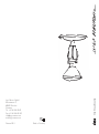
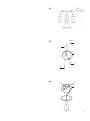
des Baldachins auf die Grundplatte und drehen diese
nach rechts, bis sich die Lasche der Grundplatte unter die
Führungslasche des Baldachins schiebt.
Schrauben Sie das Leuchtmittel fest in die Glasfassung.
Wechsel des Leuchtmittels
Achtung: Die Sicherung ausschalten und die Lampe voll-
ständig abkühlen lassen.
Technische Daten
230 V~50 Hz, 125 V~60 Hz. Die für ihre Leuchte zutreffende
Spannung und Frequenz entnehmen Sie bitte dem Typenschild.
Halogen PAR 20 Flood 30°, 75 Watt (max. 100 Watt),
Sockel E27.
Mindestabstand zu brennbaren Flächen: 0,3 m
Eventuell notwendige Reparaturen dürfen nur von einer
Elektrofachkraft durchgeführt werden.
Montage und Elektroanschluss müssen von einer Elektro-
fachkraft ausgeführt werden.
Achtung: Schalten Sie die Sicherung des Deckenauslasses
vor der Montage aus. Montieren Sie nicht auf feuchten
und leitenden Untergrund!
Der Leuchte beigepackt:
2 Schrauben und Dübel S6 (im Baldachin)
1 Leuchtmittel
Montagevorbereitung
Zum Öffnen des Baldachins drücken Sie leicht mit einem
Schraubendreher auf die Federlasche und drehen gleich-
zeitig mit der anderen Hand die Baldachinabdeckung nach
links.
Benutzen Sie die Grundplatte (1) des Baldachins zum
Markieren der beiden diagonal gegenüberliegenden Bohr-
löcher.
Montage
Wichtig: Achten Sie auf den Verlauf von Elektroleitungen,
damit auf keinen Fall ein Kabel angebohrt wird.
Bohren Sie die beiden Dübellöcher Ø 6 mm. Setzen Sie
die Dübel S6 (2) ein und schrauben Sie die Grundplatte (1)
mit den beiliegenden Schrauben (3) fest. Lassen Sie die
abgemantelten Zuleitungen des Deckenauslasses etwa 12 cm
herausragen und isolieren Sie die Enden etwa 5 mm ab.
Schließen Sie die Zuleitungen (Leiter, Neutralleiter) in der
Lüsterklemme (4) an. Nehmen Sie die Lampe und stecken
Sie den Lüsterklemmenstecker (5) in die fixierte Lüster-
klemme (4).
Zum Schließen des Baldachins setzen Sie die Abdeckplatte
1
▲
2
3
2
1
▲
▲ ▲
▲

7
English
Changing the bulb
Caution: Remove or switch off the fuse for the mains
supply and allow the lamp to cool down completely.
Technical specification
230 V~50 Hz; 125 V~60 Hz. The correct voltage and fre-
quency for your lamp are indicated on the type label.
Halogen bulb, PAR 20 flood 30°, 75 watts, max. 100 watts,
E27 socket.
Minimum distance from nearest lit surface 30 cm.
Any repairs that may become necessary must be carried
out by a qualified electrician.
▲
▲
English
6
The lamp assembly and electrical installation must be
carried out by a qualified electrician.
Caution: Switch off or remove the fuse for the mains
supply before beginning the assembly procedure. Do not
attach the lamp to a damp and/or conductive surface!
Enclosed:
2 screws and plugs S6 (in the canopy)
1 light bulb
Preparations for assembly
To open the canopy, use the tip of a screwdriver to press
gently on the catch while turning the canopy to the left
with your free hand.
Use the base plate (1) of the canopy as a guide to mark
the drill holes for the two diagonally facing screws.
Assembly
Important: Take care to ascertain the exact position of
the mains cable, so as to avoid drilling into it.
Drill the two 6mm-diameter holes. Insert the S6 plugs (2)
and attach the base plate (1) with the screws supplied (3).
Screw the base plate firmly into place. Remove a 12 cm
section of the outer covering from the mains cable and
strip about 5 mm from the ends of the three leads.
Connect the plus and minus leads to the contacts in the
terminal block (4). Now take the lamp and plug the lamp
connector (5) into the terminal block.
Close the canopy by placing the cover on the base plate
and turning the cover to the right until the catch on the
base plate engages with the lip on the canopy.
Screw the light bulb into the glass socket.
1
▲
2
3
2
1
▲
▲

Français
Pour fermer le baldaquin, appuyer le couvercle du balda-
quin sur la plaque de base et le tourner vers la droite
jusqu’au moment où la languette de la plaque de base
vient se poser en-dessous de la languette du baldaquin.
Visser l’ampoule dans la douille en verre.
Changement de l’ampoule
Attention: Débrancher le fusible et laisser refroidir la
lampe complètement.
Données techniques
230 V~50 Hz; 125 V~60 Hz. Veuillez consulter la plaque
signalétique pour la tension et la fréquence appropriée pour
votre lampe.
Ampoule halogène PAR 20 flood 30°, 75 watts, 100 watts
maximum, douille E27.
La distance aux surfaces éclairées est de 0,3 m
au minimum.
Des réparations éventuellement nécessaires ne sont à
effectuer que par un spécialiste.
9
▲
▲
0,3 m
0,5 m
1
Français
Le montage et la connexion éléctrique sont à effectuer
par un életricien qualifié.
Attention: Débrancher le fusible contrôlant l’arrivée du
courant au plafond avant le montage. Ne pas installer sur
une surface humide et/ou conductrice!
Fournitures:
2 vis et chevilles S6
1 ampoule
Préparation pour le montage
Pour ouvrir le baldaquin, appuyer légèrement sur la lan-
guette à ressort avec un tournevis et tourner en même
temps le couvercle du baldaquin vers la gauche avec l’autre
main.
Se servir de la plaque de base (1) du baldaquin pour
marquer les deux trous de perçage situés en face l’un de
l’autre en diagonale.
Montage
Important: Il est indispensable de respecter le positionne-
ment des conduites électriques afin d’éviter de percer un
câble électrique!
Percer les deux trous de cheville de Ø 6 mm. Insérer les
chevilles S6 (2) et fixer la plaque de base (1) avec les vis
jointes (3). Laisser dépasser les conduites isolées de la
sortie électrique de plafond d’environ 12 cm et dénuder
les fils d’environ 5 mm.
Connecter les alimentations (phase, phase nulle) au
domino (4). Prendre la lampe et introduire la fiche de
domino (5) dans le domino fixé (4).
8
1
▲
2
3
2
▲
▲

Italiano
la linguetta di quest’ultima slitti sotto la guida del disco di
copertura.
Avvitare la lampadina nel portalampada in vetro.
Sostituzione della lampadina
Attenzione: Staccare la corrente e attendere che la
lampada sia completamente fredda.
Dati tecnici
230 V~50 Hz; 125 V~60 Hz. I dati tecnici relativi alla tensione
e alla frequenza di funzionamento della Vostra lampada sono
riportati sulla targhetta d’identificazione.
Lampadina alogena PAR 20 Flood 30°, 75 watt,
max. 100 watt, base E27.
Distanza minima dalle superfici illuminate m. 0,3.
Eventuali riparazioni possono essere eseguite esclusivamente
da un elettricista specializzato.
11
▲
1
▲
10
Italiano
Il montaggio ed il collegamento elettrico devono essere
eseguiti da un elettricista specializzato.
Attenzione: Prima del montaggio, staccare la corrente.
Non montare su superfici umide e/o conduttrici di cor-
rente!
Nella fornitura sono inclusi:
2 viti e tasselli S6
1 lampadina
Preparazione del montaggio
Per aprire il rosone, spingere con un cacciavite delicata-
mente verso l’interno la linguetta elastica e con l’altra
mano girare contemporaneamente la copertura del rosone
verso sinistra.
Impiegare la piastra base (1) del rosone per contrassegnare
i due punti da forare disposti in diagonale.
Montaggio
Importante: Fare attenzione alla linea di alimentazione,
per evitare di danneggiare i cavi!
Effettuare i due fori per i tasselli di Ø mm. 6. Inserire i
tasselli S6 (2) e avvitare la piastra base (1) con le viti (3)
in dotazione. Lasciare spuntare i cavi di alimentazione
dell’uscita della corrente sul soffitto di circa cm. 12 e spelare
le estremità su circa mm. 5.
Collegare i cavi di alimentazione (fase, neutro) al mor-
setto (4). Prendere la lampada e collegare la parte mobile
del morsetto a spina (5) a quella fissata sulla piastra
base (4).
Per chiudere il rosone, posizionare il disco di copertura
del rosone sulla piastra base e girarlo verso destra finché
1
▲
2
3
2
▲
▲

13
2
3
2
1
Ø 6 mm
2
3
1
3
1
54
Öffnen
Open
Ouvrir
Aprire
Schließen
Close
Fermer
Chiudere
-
 1
1
-
 2
2
-
 3
3
-
 4
4
-
 5
5
-
 6
6
-
 7
7


in altre lingue
- English: Ingo Maurer Sista Operating instructions
- français: Ingo Maurer Sista Mode d'emploi
- Deutsch: Ingo Maurer Sista Bedienungsanleitung
Documenti correlati
-
Ingo Maurer Birdie Halogen Istruzioni per l'uso
-
-
-
-
-
-
-
-
-