Lince 9557-GOLD-OUT Istruzioni per l'uso
- Tipo
- Istruzioni per l'uso

IT
MODULO USCITA RADIO GOLD 869
Manuale di installazione, uso e manutenzione
EN GOLD 869 WIRELESS OUTPUT MODULE
Installation, programming and operating manual.
MADE IN ITALY
La dichiarazione CE del presente articolo
è reperibile sul sito www.lince.net.
The CE declaration of this item is available
on www.lince.net website.
MODULO
USCITA RADIO
WIRELESS OUTPUT
MODULE
ART.:
9557-GOLD-OUT

2
LINCE ITALIA S.p.A.
- Istruzioni originali -
INDICE
1. INTRODUZIONE ................................................................................................. 3
1.1 CARATTERISTICHE TECNICHE ............................................................ 3
1.2 CONTENUTO DELLA CONFEZIONE ..................................................... 3
1.3 IDENTIFICAZIONE DELLE PARTI .......................................................... 4
1.3 IDENTIFICAZIONE DELLE PARTI DELLA SCHEDA .............................. 5
2. MEMORIZZAZIONE ........................................................................................... 5
2.1 FUNZIONE SLEEP .................................................................................5
3. VERIFICA PORTATA ......................................................................................... 6
4. INSTALLAZIONE ............................................................................................... 6
5. IMPOSTAZIONI .................................................................................................. 6
6. APPLICAZIONI TIPICHE ................................................................................... 6
6.1 VIDEO VERIFICA ................................................................................... 6
6.2 ACCENSIONE CALDAIA ....................................................................... 7
6.3 ACCENSIONE LAMPADA ...................................................................... 7
7. MANUTENZIONE E VERIFICHE PERIODICHE ................................................ 8
8. SMALTIMENTO E ROTTAMAZIONE ................................................................. 8
- Translation of the original instructions (original instructions in Italian) -
Le informazioni riportate in questo manuale sono state compilate
con cura, tuttavia LINCE ITALIA S.p.A. non può essere ritenuta
responsabile per eventuali errori e/o omissioni. LINCE ITALIA
S.p.A. si riserva il diritto di apportare in ogni momento e senza
preavviso, miglioramenti e/o modiche ai prodotti descritti
nel presente manuale. Consultare il sito www.lince.net per le
condizioni di assistenza e garanzia. LINCE ITALIA S.p.A. pone
particolare attenzione al rispetto dell’ambiente. Tutti i prodotti ed i
processi produttivi sono progettati con criteri di eco-compatibilità.
Il presente articolo è stato prodotto in Italia.
L’azienda ha un sistema di gestione della qualità certicato secondo
la norma ISO 9001:2008 (n° 4796 - A)
L’azienda ha un sistema di gestione ambientale certicato secondo
la norma ISO 14001:2004 (n° 4796 - E)
L’azienda ha un sistema di gestione della salute e sicurezza sul
lavoro certicato secondo la norma ISO 45001:2018 (n° 4796 - I)
The information in this manual has been issued with care, but
LINCE ITALIA S.p.A. will not be responsible for any errors or
omissions. LINCE ITALIA S.p.A. reserves the right to improve
or modify the products described in this manual at any time
and without advance notice. Terms and conditions regarding
assistance and the product warranty can be found at LINCE
ITALIA’s website www.lince.net. LINCE ITALIA S.p.A. makes it a
priority to respect the environment. All products and production
processes are designed to be eco-friendly and sustainable.
This product has been Made in Italy
The company has a certied system of quality management
according to ISO 9001:2008 (n° 4796 - A) standard.
The company has a certied system of environmental management
according to ISO 9001:2004 (n° 4796 - E) standard.
The company has a certied system of health and work security
management according to ISO 45001:2018 (n° 4796 - I) standard.
1. INTRODUCTION ................................................................................................ 3
1.1 TECHNICAL FEATURES ........................................................................ 3
1.2 PACKAGING CONTENTS ....................................................................... 3
1.3 PARTS IDENTIFICATION........................................................................ 4
1.3 BOARD PARTS IDENTIFICATION .......................................................... 5
2. PAIRING ............................................................................................................ 5
2.1 SLEEP FUNCTION ................................................................................ 5
3. WIRELESS RANGE CHECK ............................................................................ 6
4. INSTALLATION ................................................................................................. 6
5. SETTINGS .......................................................................................................... 6
6. TYPICAL APPLICATION .................................................................................... 6
6.1 VIDEO VERIFICATION ..........................................................................6
6.2 BOILER IGNITION .................................................................................7
6.3 LAMP POWER ON ................................................................................. 7
7. MAINTENANCE AND PERIODIC CHECKS ...................................................... 8
8. DISPOSAL AND SCRAPPING ........................................................................... 8
CONTENTS

3
LINCE ITALIA S.p.A.
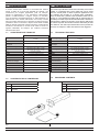
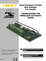
1.2 CONTENUTO DELLA CONFEZIONE
Fig. 1
1. INTRODUZIONE
Il modulo Uscita Radio estende le funzionalità del sistema
GOLD, è dotato di un uscita relé pilotabile da centrale o da
combinatore per svolgere applicazioni quali, ad esempio:
attivare la registrazione di una telecamera (videoverica);
pilotare un’elettroserratura; svolgere compiti di domotica,
come ad esempio accendere/spegnere un elettrodomestico (in
abbinamento a una scheda relè esterna non fornita). L’uscita
radio può essere associata ad un rilevatore per attivarsi quando
quest’ultimo rileva un’intrusione; dispone inoltre della modalità
AND per attivarsi solamente quando l’intrusione è stata rilevata
da almeno due rilevatori. Il modulo uscite radio ha anche un
ingresso utilizzabile, ad esempio, per vericare l’avvenuta
attivazione del carico.
A
B
Tabella 1
Part. Identicazione
AModulo
Bmanuale
1.1 CARATTERISTICHE TECNICHE
9557-GOLD-OUT
Alimentazione Batteria al litio AA (LiSOCl2) 3,6 V 2200 mAh
(inclusa)
Consumo 12 μA
Carico massimo pilotato
dall'uscita 12 Vcc @ 1 A
Caratteristiche ingresso Ingresso NC riferito a massa
Frequenze di trasmissione 869,40 MHz-869,65 MHz 1 canale,
868,00 MHz-868,60 MHz 4 canali
FH Frequency Hopping
TDMA Time Division Multiple Access
AES Advanced Encryption Standard
Portata no a 1500 m in aria libera
Protezione contro
l’apertura e lo strappo microswitch
Classe ambientale Classe II (da interno)
Immunità alla radiofrequenza EN50130-4
Temperatura di esercizio -10 °C ~ +40 °C
Dimensioni 135 x 35 x 24 mm
1. INTRODUCTION
The Radio Output Module extends the functionality of the GOLD
system, it is equipped with a relay output that can be drived
from the control panel or dialer to perform applications such
as: activating the recording of a camera (video verication);
drive an electro-lock; perform home automation tasks such as
turning on / off an appliance (together with an external relay not
provided). The radio output can be associated with a detector to
activate when it detects an intrusion; it has also the AND mode
to activate only when the intrusion has been detected by at least
two detectors. The radio output module also has a input that can
be used, for example, to make sure that the load is triggered.
1.2 PACKAGING CONTENTS
Table 1
Part. Identication
AModule
BProduct manual
1.1 TECHNICAL FEATURES
9557-GOLD-OUT
Operating voltage Lithium battery AA (LiSOCl2) 3,6 V 2200 mAh
(included)
Power consumotion 12 μA
Maximum load driven by
the output 12 Vdc @ 1 A
Input features NC input referred to ground
Operating frequency 869,40 MHz-869,65 MHz 1 canale,
868,00 MHz-868,60 MHz 4 canali
FH Frequency Hopping
TDMA Time Division Multiple Access
AES Advanced Encryption Standard
Wireless range up to 1500 m in free air
Protection against tamper
and wall removal microswitch
Class Class II (indoor)
Radiofrequency immunity EN50130-4
Working temperature -10 °C ~ +40 °C
Dimensions 135 x 35 x 24 mm

4
LINCE ITALIA S.p.A.
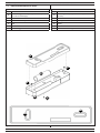
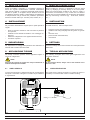
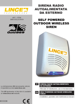
1.3 IDENTIFICAZIONE DELLE PARTI
Fig. 2
A
A
E
D
C
Tabella 2
Part. Identicazione
AFori di ssaggio a muro (Collegare entrambi per avere
la funzione antistrappo)
BCoperchio
CVite di chiusura coperchio
DPila
EFondo
FViti di ssaggio scheda
B
F
F
1.3 PARTS IDENTIFICATION
Table 2
Part. Identication
AWall xing holes (xing both holes for get the anti-tear
function)
BLid
CClosing cover screw
DBattery
EBase
FScrews for board xing

5
LINCE ITALIA S.p.A.
NOTA:
Nel caso la periferica fosse già stata memorizzata sul display
compare la voce “periferica già presente”.
Se si desidera riportare la periferica alle impostazioni di fabbrica
premere per 10 volte il microswitch antisabotaggio.
NOTE:
If the device has already been stored the message“peripheral
device already present” appears on the display.
If you want to return the device to the factory settings, press the
antitamper microswitch for 10 times
Fig. 3
1.4 IDENTIFICAZIONE DELLE PARTI DELLA
SCHEDA
1.4 BOARD PART IDENTIFICATION
2. MEMORIZZAZIONE
Prima di installare la periferica procedere alla memorizzazione
seguendo i passi riportati di seguito:
1. impostare la centrale GOLD 869 o il modulo TX/RX GOLD
869 in apprendimento periferiche facendo riferimento al
relativo manuale;
2. aprire il contatto;
3. Inserire la pila D come indicato in gura 2. Il LED rosso
comincierà a lampeggiare ad intermittenza.
4. Premere per tre volte il microswitch antisabotaggio per
inviare la trama di memorizzazione. Il LED rosso cesserà
di lampeggiare.
Tabella 3
Part. Identicazione
AVano Pila (rispettare la polarità indicata)
BRelè
CMicroswitch antisabotaggio
DMorsettiera uscita
EMorsettiera ingresso
Table 3
Part. Identication
Apile compartment (observe the indicated polarity)
Brelay
CAnti-tamper microswitch
DOutput terminal block
EInput terminal block
A
B
C
D
E
2.1 FUNZIONE SLEEP
Questa funzione pone la periferica in uno stato dormiente a
basso consumo (in cui non trasmette); nel caso debba essere
rimossa la centrale per eventuale manutenzione. La periferica
una volta entrata in questa modalità dopo un'ora si riattiva per
un minuto, controllando la presenza della trama della centrale
e, qualora non sia presente, rientra in uno stato dormiente no
all'ora successiva.
2. PAIRING
Before to install the device proceed to pair it by following the
steps below:
1. set the control panel GOLD 869 or TX / RX module GOLD
869 in the storage mode by referring to the manual;
2. open the contact;
3. Insert the battery D as shoen in gure 2. The red LED will
begin to ash intermittently;
4. Press for three times the tamper microswitch to send the
storage message. The red LED will stop ashing.
2.1 SLEEP FUNCTION
This function puts the device in a sleepy low-power state (where
not transmitting); in case the control panel must to be removed
for maintenance. The device once you enter this mode after
an hour wakes for a minute by controlling the presence of the
message of the control panel and, if not present, fall again into a
sleepy state until the next hour.

6
LINCE ITALIA S.p.A.
5. IMPOSTAZIONI
Per impostazioni e settaggi della periferica fare riferimento al
manuale della centrale serie GOLD 869.
Per procedere all'installazione seguire quindi i passi riportati di
seguito:
• Aprire il coperchio svitando la vite di chiusura C presente
sul coperchio;
• installare il fondo utilizzando tasselli e i fori di ssaggio "A"
(gura 2);
• effettuare i collegamenti con le apparecchiature esterne;
• chiudere il coperchio.
3. VERIFICA PORTATA
Prima di installare il dispositivo è consigliabile vericare la
bontà del segnale visualizzandone l'intensità direttamente
sulla centrale. Disturbi e condizioni ambientali infatti possono
alterarne la qualità; è consigliato dunque effettuare il test ad
una distanza superiore rispetto a quella effettiva di installazione
e interponenendo tutti gli ostacoli che potrebbero presentarsi
durante il normale utilizzo (es.: chiudere porte, nestre, etc...).
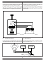
6. APPLICAZIONI TIPICHE
Gli esempi successivi riportano alcune applicazioni tipiche e
schemi di collegamento.
NOTA:
Negli esempi riportati di seguito fare sempre riferimento ai
manuali dei dispositivi utilizzati
6. TYPICAL APPLICATION
The following examples show some typical applications and
connection schemes.
NOTE:
In the examples below, always refer to the manuals of the
devices in use.
Fig. 4
6.1 VIDEO VERIFICA
In gura viene riportato un collegamento tipico di una telecamera
alla quale è necessario collegare un contatto NA per abilitarne
la registrazione.
6.1 VIDEO VERIFICATION
The gure shows a typical connection of a camera to which it is
necessary to connect an NO contact to enable recording.
USCITA
OUTPUT
5. SETTINGS
For device settings refer to the manual of the control panel series
GOLD 869.
To install the device, follow the steps below:
• Open the cover by unscrewign the screw C on the cover;
• install the base using wall plugs and xing holes "A" (picture
2);
• close the cover;
• place wire with external devices;
• close the lid.
4. INSTALLAZIONE 4. INSTALLATION
3. WIRELESS RANGE CHECK
Before installing the device it is advisable to verify the signal
quality by displaying its intensity directly on the control panel.
Noise and environmental conditions may alter its quality; it
is therefore, recommended, to carry out the test at a distance
greater than the actual installation and interposing all obstacles
that may arise during normal use (eg .: close doors, windows,
etc...).

7
LINCE ITALIA S.p.A.
Fig. 5
6.2 ACCENSIONE CALDAIA
In gura viene riportato il tipico collegamento di una caldaia con
comando NA no a 1 A massimo. Nel caso il comando sia a 220
Vca, utilizzare un relè a 12 Vcc tra il modulo e la caldaia.
È possibile sfruttare anche l'ingresso per conoscere lo stato
della caldaia se la caldaia ha un comando di stato impianto
con scambio C-NC-NA. Se sullo stato impianto della caldaia è
presente una tensione, è consigliato l'uso di un relè esterno.
6.1 BOILER IGNITION
The gure shows the typical connection of a boiler with an NO
command up to 1 A massimo. If the control is at 220 Vac, use a
12 Vdc relay between the module and the boiler.
The input can also be used to know the status of the boiler if the
boiler has a system a C-NC-NO status command. If a voltage is
present on the boiler system status, the use of an external relay
is recommended.
Fig. 6
12 Vdc220Vac
6.3 ACCENSIONE LAMPADA
In gura viene riportato un collegamento tipico per l'accensione
di una lampada utilizzando un relè a 12 Vcc. Lo schema è valido
anche per l'accensione di qualsiasi carico alimentato a 220 Vca.
6.3 LAMP POWER ON
The gure shows a typical connection for switching on a lamp
using a 12 Vdc relay. The scheme is also valid for the ignition of
any load powered at 220 Vac.
USCITA
OUTPUT
USCITA
OUTPUT
INGRESSO
INPUT
C
NC
NA

001530/00933AB Rev0
LINCE ITALIA S.p.A
Via Variante di Cancelliera, snc
00072 ARICCIA (Roma)
Tel. +39 06 9301801
Fax +39 06 930180232
www.lince.net
7. MANUTENZIONE E VERIFICHE PE-
RIODICHE
Al ne di garantire il corretto funzionamento, è necessario sosti-
tuire la batteria ogni 2 anni
ATTENZIONE! Per rimuovere sporcizie particolar-
mente evidenti NON utilizzare prodotti a base di cl-
GOLD, prodotti abrasivi oppure alcool.
1. Pulire il coperchio con un panno inumidito con acqua.
2. Ripassare con un panno asciutto.
8. SMALTIMENTO E ROTTAMAZIONE
1. Rimuovere il coperchio frontale.
2. Scollegare la scheda: sulla morsettiera scollegare tutti i mor-
setti (v. Fig. 3).
3. Dividere le parti in base alla lGOLD tipologia e smaltirle in
accordo con le leggi vigenti.
ATTENZIONE!
Non disperdere nell’ambiente i componenti ed ogni
altro materiale del prodotto.
Rivolgersi a consorzi abilitati allo smaltimento ed al riciclag-
gio dei materiali.
7. MAINTENANCE AND PERIODIC
CHECKS
In order to guarantee the correct work, is compulsory to replace
the battery every 2 years.
IMPORTANT!
Do NOT use chlorine-based or abrasive products or
alcohol to remove particularly noticeable dirt.
1. Clean the lid with a cloth dampened with water.
2. Wipe with a dry cloth.
8. DISPOSAL AND SCRAPPING
1. Remove the front lid.
2. Disconnect the board: disconnect all the terminals on the ter-
minal block (see Fig. 3).
3. Divide the parts by type and dispose of them in accordance
with applicable laws.
IMPORTANT!
Do not dispose of the components or any other pro-
duct material in the environment.
Seek the assistance of companies authorised to dispose of
and recycle waste materials.
-
 1
1
-
 2
2
-
 3
3
-
 4
4
-
 5
5
-
 6
6
-
 7
7
-
 8
8


Lince 9557-GOLD-OUT Istruzioni per l'uso
- Tipo
- Istruzioni per l'uso
in altre lingue
Documenti correlati
-
 Lince 9553-GOLD-BOBBY-AM-E Istruzioni per l'uso
-
 Lince 9518-GOLD-OBLO/L Istruzioni per l'uso
-
 Lince 9587-GOLD-AG Istruzioni per l'uso
-
 Lince 9590-GOLD-SMOKE Istruzioni per l'uso
-
 Lince 9521-GOLD-TXRX Istruzioni per l'uso
-
 Lince 9560-GOLD-SAXA Istruzioni per l'uso
-
 Lince 9547-GOLD-SOFT Istruzioni per l'uso
-
 Lince 9582-GOLD-MST-E-EN Istruzioni per l'uso
-
 Lince OBLO'/E Istruzioni per l'uso
-
 Lince 1943-ONDA4-A Istruzioni per l'uso


