Kichler Lighting 15066AZT Manuale utente
- Tipo
- Manuale utente
La pagina si sta caricando...
La pagina si sta caricando...

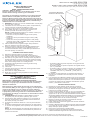
SAFETY INSTRUCTIONS
1) WARNING: This fixture is not to be installed within 10 feet (3M) of a pool, spa or fountain.
2) This fixture is to be used only with a power unit (transformer) rated a maximum of 300 W (25 AMPS) 15 volts.
3) The 8, 10, or 12 GA wiring is intended for shallow burial. Do not bury deeper than 6 inches (152 mm) below the surface.
NOTE: If more wire is needed, contact your local Kichler landscape distributor.
• 8 GA wire can be purchased in length of 250’ (76 M), 15503-BK.
• 10 GA wire can be purchased in length of 250’ (76 M), 15504-BK.
• 12 GA wire can be purchased in lengths of 75’ (22 M), 15500-BK; 100’ (30 M), 15501-BK; 250’ (76 M), 15502-BK; 500’ (152M), 15505-BK; and 1000’
(304 M) 15506-BK.
4) Fixture shall not use a tungsten halogen lamp unless the fixture is marked for use with such lamps.
INSTRUCCIONES DE SEGURIDAD
1) ADVERTENCIA: Este artefacto no debe instalarse a menos de 10 pies (3 m) de una piscina (alberca), spa o fuente.
2) Este artefacto debe utilizarse solamente con una unidad de potencia (tranformador) con capacidad nominal máxima de 300 vatios (25 amp.) 15 voltios.
3) Los alambres calibre 8, 10 y 12 son para entierro poco profundo. No entierre a más de 6 pulgadas (152 mm.) debajo de la superficie.
Nota: Si se necesita más alambre, comuníquese con su distribuidor de local Kichler de artículos para paisajes de terreno.
• El alambre calibre 8 puede comprarse en longitud de 250’ (76 m.), 15503-BK
• El alambre calibre 10 puede comprarse en longitud de 250’ (76 m.), 15504-BK
• El alambre calibre 12 puede comprarse en longitudes de 75’ (22 m.), 15550-BK; 100’ (30 m.), 15501-BK; 250’ (76 m.), 15502-BK; 500’ (152 m.), 15505-
BK; y 1000’ (304 m.), 15506-BK.
4) El artefacto no debe utilizarse con lámparas de halógeno, a menoss que el artefacto esté marcado para usar con tales lámparas.
A UTILISER UNIQUEMENT POUR LES SYSTÈMES D’ÉCLAIRAGE PAYSAGER
1) Le dispositif est accepté en tant que composant d’un système d’éclairage paysager lorsque la compatibilité de la combinaison étiquetée UL ou CSA
(ACNOR) doit être déterminée par CSA, UL respectivement ou les autorités d’inspection locales ayant compétence.
2) L’appareil doit étre connecté à un transformateur supplémentaire à basse tension approuvé pour une utilisation avec les systémes d’éclairage paysager.
3) Cet apareil doit étre connecté à un câblage secondaire du type suivant:
12GA 60°C type minimum;
SPT-3 combatible pour utilisation extreme;
ou câble d’éclairage paysager agréé.
ISTRUZIONI PER LA SICUREZZA
1) Avvertenza: l'unità non va installata entro 10 piedi (3 metri) da piscine, vasche idromassaggio o fontane.
2) Questa unità va usata solo con un'unità di alimentazione (trasformatore) con una portata massima di 300 W (25 ampere), 15 Volt.
3) Il filo da 8, 10 o 12 GA è inteso per buche poco profonde. NON scavare oltre 6 pollici (152 mm) sotto la superficie.
NOTA: se occorre più cavo, rivolgersi al distributore Kichler® di zona.
• Il filo da 8 GA può essere acquistato in lunghezze da 250 piedi (76 metri), 15503-BK.
• Il filo da 10 GA può essere acquistato in lunghezze da 250 piedi (76 metri), 15504-BK.
• Il filo da 12 GA può essere acquistato in lunghezza da 75 piedi (22 metri), 15500-BK; 100 piedi (30 metri), 15501-BK; 250 piedi (76 metri), 15502-BK;
500 piedi (152 metri), 5505-BK ed 1000 piedi (304 metri) 15506-BK.
4) L'unità non utilizza una lampadina alogena al tungsteno a meno che non sia contrassegnata per l'uso con tale tipo di lampadine.
SICHERHEITSANWEISUNGEN
1) ACHTUNG: Der Abstand zwischen der installierten Lampe oder Zubehör und einem Pool, Schwimmbad, einer Heilquelle, einem Heilbad oder Springbrunnen
muß mindestens 3 m betragen.
2) Diese Lampe darf nur mit Stromversorgungseinheiten (Wandlern) verwendet werden, die für maximal 300 Watt (25 Ampere Sekunden) x 15 Volt
ausgelegt sind.
3) Die 8, 10, oder 12 GA* Kabel sind für das Verlegen flach unter der Erde vorgesehen und sollten nicht tiefer als 15 cm unter der Oberfläche verlegt werden.
ANMERKUNG: Wenn Sie zusätzliches Kabel benötigen, wenden Sie sich bitte an Ihren örtlichen Händler für Kichler Landschaftsbeleuchtungen.
• 8 GA Kabel wird in einer Länge von 76 m angeboten: 15503-BK.
• 10 GA Kabel wird in einer Länge von 76 m angeboten: 15504-BK.
• 12 GA Kabel ist in den folgenden Längen erhältlich: 22 m (15500-BK), 30 m (15501-BK), 76 m (15502-BK), 152 m (15505-BK) und 304 m (15506-BK).
4) Tungsten (Wolfram)-Halogenlampen dürfen nur installiert werden, wenn die Bezeichnung der Beleuchtungsanlage die Verwendung dieser
Lampen ausdrücklich vorsieht.
IS-15066-EURDate Issued: 9/30/05
WARRANTY
WE WARRANT THE LANDSCAPE PRODUCTS FEATURED IN OUR LANDSCAPE LIGHTING CATALOG (WITH THE EXCEPTION OF LIGHT BULBS) FOR FIVE
YEARS AGAINST DEFECTS IN MATERIALS AND WORKMANSHIP IF IT WAS PROPERLY INSTALLED AND FAILED UNDER NORMAL OPERATING CONDI-
TIONS, PROVIDED IT IS RETURNED TO THE POINT OF PURCHASE, WHERE IT WILL BE REPAIRED OR, AS IT MAY BE DETERMINED, TO REPLACE THE
LANDSCAPE PRODUCT OR PARTS USED ON THAT PRODUCT.
GARANTIA
NOSOTROS GARANTIZAMOS POR CINCO ANOS LOS PRODUCTOS PANORAMICOS QUE OFRECEMOS EN NUESTRO CATALOGO DE ILUMINACION
PANORAMICA (CON EXCEPCION DE LAS BOMBILLAS), QUE ESTAN EXENTOS DE DEFECTOS DE MATERIALES Y MANO DE OBRA, SI SE INSTALARON
CORRECTAMIENTE Y FALLARON EN CONDICIONES DE OPERACION NORMAL, SIEMPRE QUE SE DEVUELVAN AL LUGAR DE COMPRA, DONDE SERAN
REPARADOS O, SEGUN PUEDA DETERMINARSE, SERAN
GARANTIE
NOUS GARANTISSONS LES PRODUITS DE PAYSAGES FIGURANT DANS NOTRE CATALOGUE DES LUMIERES PAYSAGISTES (A L’EXCEPTION DES
AMPOULES) PENDANT UNE PERIODE DE CINQ ANS CONTRE TOUS DEFAUTS DE MATERIAUX ET DE MAIN D’OEUVRE SOUS CONDITION QUE L’IN-
STALLATION AIT ETE EFFECTUEE CORRECTEMENT ET QUE LES PROBLEMES SE SOIENT PRODUITS AU COURS D’UN EMPLOI NORMAL. LE PRODUIT
DOIT ETRE RETOURNE AU LIEU DE VENTE OU IL SERA REPARE OU, SUITE A UNE EVALUATION, LE PRODUIT DE PAYAGE OU LES PIECES QUI LE COM-
POSENT SERONT REMPLACEES.
GARANTIE
WIR GARANTIEREN DIE LANDSCHAFTSPRODUKTE, DIE IN UNSEREM KATALOG MIT LANDSCHAFTSBELEUCHUNGSSYSTEMEN ANGEBOTEN WER-
DEN (MIT AUSNAHME DER GLÜHBIRNEN), FÜR FÜNF JAHRE. DIE GARANTIE DECKT MATERIALFEHLER UND DIE HANDWERKLICHE AUSFÜHRUNG,
SOLANGE DIE TEILE FACHGERECHT EINGEBAUT WERDEN UND DIE MÄNGEL UNTER NORMALEN BEDINGUNGEN DER VERWENDUNG AUFTRETEN,
VORAUSGESETZT, DASS DAS TEIL/ PRODUKT AM EINKAUFSORT ZURÜCKGEGEBEN WIRD. DAS PRODUKT WIRD DORT REPARIERT ODER, JE NACH
BEURTEILUNG, KANN DAS TEIL / LANDSCHAFTSBELEUCHTUNGSSYSTEM AUCH ERSETZT WERDEN.
GARANZIA
GARANTIAMO I PRODOTTI DA ESTERNO CONTENUTI IN QUESTO CATALOGO (AD ECCEZIONE DELLE LAMPADINE) PER UN PERIODO DI CINQUE ANNI
DA DIFETTI DI MATERIALE E MANODOPERA, SE DEBITAMENTE INSTALLATI, CHE SI GUASTANO IN CONDIZIONI OPERATIVE REGOLARI, AMMESSO
CHE VENGANO RESTITUITI AL CENTRO DI ACQUISTO, DOVE VERRANNO RIPARATI, OPPURE, A SECONDA DEL CASO, SOSTITUITI CON PRODOTTI O
PARTI DA ESTERNO USATI SUL PRODOTTO IN QUESTIONE.

IS-15066-EUR
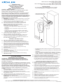
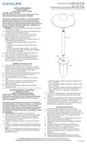
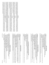
ASSEMBLY AND INSTALLATION
1) Determine desired location for mounting fixture.
2) Using mounting bracket as a template, mark position of mounting holes.
Also mark bottom edge of mounting bracket.
3) Drill 3/32” (2 mm) pilot holes in mounting surface at positions marked. Also
drill 1/4” (6 mm) wireway hole. Position wireway hole directly under pilot
holes and approximately 1/2” (12mm) below line marking bottom of mount-
ing bracket.
4) Assemble mounting bracket to mounting surface using provided screws.
5) Pass wire through wireway hole.
6) Insert bulb.
7) Carefully slip housing over bulb and mounting bracket. Slide housing down
until snug.
8) Turn off power, disconnect or unplug transformer and make connection fol-
lowing Quic Disc
®
instructions.
MONTAJE E INSTALACIÓN
1)
Determinar el lugar deseado donde montar el artefacto.
2)
Utilizando la consola de montaje como plantilla, marcar la posición de los
agujeros de montaje. También marcar el borde inferior de la consola de
montaje.
3)
Perforar agujeros pilotos de 3/32" (2 mm.) en la superficie de montaje, en
las posiciones marcadas. También perforar un agujero de 1/4" (6 mm.) en
el canal de alambres. Colocar el agujero del canal de alambres directa-
mente debajo de los agujeros pilotos y aproximadamente a 1/2" (12 mm.)
debajo de la línea que marca la parte inferior de la consola de montaje.
4)
Montar la consola de montaje a la superficie de montaje utilizando los
tornillos que se proveen.
5)
Pasar el alambre a través del agujero del canal de alambres.
6)
Insertar la bombilla.
7)
Deslizar cuidadosamente la cubierta protectora sobre la bombilla y la con-
sola de montaje. Deslizar la cubierta protectora hacia abajo hasta que
quede ajustada.
8)
Apagar la alimentación eléctrica, desconectar o desenchufar el transfor-
mador y hacer la conexión siguiendo las instrucciones de Quic Disc
®
.
MONTAGE ET INSTALLATION
1) Déterminer l’endroit désiré où installer l’appareil.
2) Marquer la posiion des trous de fixation en se servant du support d’attache
comme gabarit. Marquer également le bord inférieur du support d’attache.
3) Percer des trous de positionnement de 2 mm (3/32 po) dans la surface de
montage aux endroits marqués. Percer également un trou de 6 mm (1/4 po)
pour passer le fil électrique. Placer ce trou directement sous les trous de
positionnement et approximativement à 12 mm (1/2 po) sous la ligne indiquant
le bord inférieur du supportd’attache.
4) Fixer le support d’attache à la surface de montage avec les vis incluses.
5) Passer le fil dans le trou.
6) Mettre une ampoule.
7) Glisser avec précaution le boîter sur l’ampoule et le support d’attache. Glisser le boîtier jusqu’à ce qu’il s’encastre.
8) Couper l’alimentation électrique, déconnecter ou débrancher le transformateur et faire les connexions en suivant les instructions pour la pose des fils du
Quic Disc
®
.
MONTAGEANLEITUNG
1) Bestimmen Sie einen Platz für Ihre Lampe.
2) Markieren Sie die Stellen für die Vorbohrungen. Die Halterung dient dabei als Vorlage. Bezeichnen Sie auch die untere Kante der Halterung.
3) Machen Sie 2 mm Vorbohrungen in den markierten Positionen in der Montagefläche. Bohren Sie auch ein 6 mm Loch für die Leitungsführung. Das Loch
für die Leitungsführung sollte direkt unter den Vorbohrungen und ungefähr 12 mm unter der Markierung für das untere Ende der Halterung sein.
4) Befestigen Sie die Halterung mit den einbegriffenen Schrauben an der Montagefläche.
5) Führen Sie das elektrische Kabel durch das dafür gebohrte Loch.
6) Setzen Sie die Glühbirne ein.
7) Führen Sie das Gehäuse vorsichtig über die Birne und die Halterung und gleiten Sie es nach unten bis es fest aufsitzt.
8) Den Strom abschalten, den Umformer unterbrechen oder den Stecker herausziehen und dann den Anschluß herstellen. Befolgen Sie dabei die Quic Disc
®
Anweisungen.
ISTRUZIONI PER IL MONTAGGIO
1) Determinare la posizione desiderata per l'attrezzo di montaggio.
2) Con la piastra di montaggio come mascherina, contrassegnare la posizione dei fori di montaggio. Contrassegnare anche il bordo inferiore della piastra di
montaggio.
3) Praticare fori pilota da 2 mm nella superficie di montaggio, sulle posizioni contrassegnate. Praticare un filo di passaggio da 1/4 di pollice (6 mm).
Posizionare il foro di passaggio direttamente sotto i fori pilota ed a circa 1/2 pollici (12 mm) sotto la linea che contrassegna il fondo della piastra di mon-
taggio.
4) Montare la piastra alla superficie di montaggio utilizzando le viti in dotazione.
5) Far passare il filo attraverso il foro.
6) Inserire la lampadina.
7) Far scorrere con attenzione l'alloggiamento sulla lampadina e la piastra di montaggio. Far scorrere verso il basso l'alloggiamento fin quando non aderisce.
8) Togliere corrente, scollegare o staccare il trasformatore ed effettuare il collegamento attenendosi alle istruzioni Quic Disc
®
.
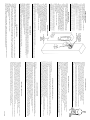
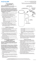
QUIC DISC
®
WIRING INSTRUCTIONS
Turn off power.
The full length of the 18 GA fixture wire may be used to connect with the 10 GA or 12 GA cable provided the following conditions are met:
• Wiring is to be protected by routing close to the fixture or accessory or secured to a building structure such as house or deck.
• 18 GA fixture wiring is to be cut off so that it is attached to the connector within 6 inches of the fixture or building structure.
• If it is necessary to make the connections underground, then no more than 6 inches of the 18 GA fixture wire is to be buried.
The Quic Disc
®
connector accommodates one 18 GA fixture wire and one 10 GA or one 12 GA supply wire.
Place the 10 gauge supply wire across the area marked 10 GA on Quic Disc
®
or place the 12 gauge supply wire across the area marked 12 GA on
Quic Disc
®
.
Place the 18 gauge fixture wire across the area marked 18 GA on the Quic Disc
®
. After the wires are in place, connect the top of the Quic Disc
®
to
the base with supplied screw, making sure that the wires remain flat in the bottom portion of the Quic Disc
®
, and the screw is tightened all the way
down.
The copper contacts will automatically pierce the wires’ insulation. Excess 18 GA fixture wire that sticks out the end of the Quic
Disc
®
is to to be cut off.
QUIC DISC® ANSCHLUSSANLEITUNGEN
Den Strom abschalten.
Die volle Länge des 18 GA Lampenkabels kann für den Anschluß an das 10 GA oder 12 GA Kabel verwendet werden, solange die folgenden Bedingungen erfüllt sind:
• Zum Schutz der Leitung müssen Kabel nahe der Lampe und Zubehör verlegt werden oder unmittelbar an einer baulichen Struktur angebracht sein, wie z.B. an einemHaus oder
einer Terrasse.
• Das 18 GA-Kabel muß abgeschnitten werden, so daß es innerhalb von 15,24 cm vom Beleuchungssystem oder einem Gebäude an eine Buchse angeschlossen ist.
• Wenn der Anschluß unterhalb der Erde gemacht werden muß, dürfen nicht mehr als 15,24 cm des 18 GA-Kabels unter der Erde verlegt sein.
Der Quic Disc
®
Konnektor kann ein 18 GA-Kabel und ein 10 GA- oder 12 GA-Kabel für die Stromversorgung aufnehmen.
Auf dem Quic Disc
®
Konnektor das 10 GA-Kabel für die Stromzufuhr über den Bereich mit der Markierung "10 GA" oder das 12 GA-Kabel über den "12 GA" Bereich legen.
Auf dem Quic Disc
®
Konnektor das 18 GA-Lampenkabel über den Bereich mit der Markierung "18 GA" legen. Mit den Kabeln richtig angeordnet, legen Sie den Quic Disc
®
Konnektor-Deckel auf das Unterteil und befestigen Sie den Deckel locker mit der beiliegenden Schraube. Wenn Sie sicher sind, daß die Kabel flach im Unterteil des Quic Disc®
Konnektors liegen, ziehen Sie die Schraube so fest wie möglich an.
Die Kupferkontakte brechen automatisch durch die Kabelisolierung. Überschüssiges 18 GA-Kabel, das über den Quic Disc
®
Konnektor hinausreicht, muß abgeschnitten werden.
ISTRUZIONI PER IL CABLAGGIO QUIC DISC
®
Togliere corrente.
Potrebbe essere necessario utilizzare l'intera lunghezza del filo dell'attrezzo da 18 GA per collegare il cavo da 10 GA o da 12 GA, ammesso che esistano le seguenti condizioni:
• Il cablaggio deve essere protetto disponendolo accanto all'attrezzo o all'accessorio o fissandolo ad una struttura, quale la casa o il balcone in legno.
• Il filo dell'attrezzo da 18 GA va tagliato di modo che sia fissato al connettore senza superare una distanza di 6 pollici dall'attrezzo stesso o dalla struttura in questione.
• Occorre effettuare collegamenti sotterranei, senza sotterrare comunque non più di 6 pollici del filo dell'attrezzo da 18 GA.
Il connettore Quic Disc
®
prevede l'utilizzo di un filo dell'attrezzo da 18 GA e di due fili di alimentazione, uno da 10 GA ed uno da 12 GA.
Sistemare il filo di alimentazione da 10 GA attraverso l'area contrassegnata 10 GA su Quic Disc
®
, oppure il filo di alimentazione da 12 GA attraverso l'area contrassegnata 12 GA
su Quic Disc
®
.
Sistemare il filo dell'attrezzo da 18 GA attraverso l'area contrassegnata 18 GA su Quic Disc
®
. Dopo aver sistemato i fili, collegare la sommità del Quic Disc
®
alla base avvalendosi
della vite in dotazione ed accertandosi che i fili restino piatti nella sezione inferiore del Quic Disc
®
e che la vite sia serrata fino in fondo.
I contatti in rame perforano automaticamente l'isolamento dei fili. Tagliare il filo dell'attrezzo da 18 GA che spunta dall'estremità del Quic Disc
®
.
INSTRUCCIONES DE ALAMBRADO DE QUIC DISC
®
Apague la alimentación de energía.
El largo total del alambre calibre 18 del artefacto se puede utilizar para conectar con un cable calibre 10 ó 12, con tal que se cumplan las condiciones siguientes:
• El alambrado se debe proteger encaminando cerca al artefacto o accesorio o asegurado a la estructura de un edificio, tal como una casa o cubierta.
• El alambrado calibre 18 del artefacto debe cortarse de manera que se una al conector dentro de las 6 pulgadas del artefacto o de la estructura del edificio.
• Si fuere necesario hacer las conexiones bajo tierra, como máximo 6 pulgadas del alambre calibre 18 del artefacto se debe enterrar.
El conector Quic Disc
®
acomoda un alambre calibre 18 del artefacto y uno calibre 10 o un alambre de alimentación calibre 12.
Coloque el alambre de alimentación calibre 10 a través del área marcada calibre 10 en el Quic Disc
®
o ponga el alambre de alimentación calibre 12 a través del área marcada cal-
ibre 12 en el Quic Disc
®
.
Ponga el alambre calibre 18 del artefacto a través del área marcada calibre 18 en el Quic Disc
®
Después que los alambres estén en su lugar, conecte el tope del Quic Disc
®
a la
base con el tornillo que se provee, asegurándose de que los alambres permanezcan en la porción inferior del Quic Disc
®
, y el tornillo esté todo apretado hacia abajo.
Los contactos de cobre automáticamente perforarán la aislación de los alambres. El exceso de alambre calibre 18 del artefacto que sobresale del extremo Quic Disc
®
debe cortarse.
INSTRUCTIONS DE CBLAGE ÉLECTRIQUE AVEC UN QUIC DISC
®
Couper le courant d'alimentation.
Toute la longueur du fil électrique de calibre 18 peut être utilisée pour le branchement avec le fil électrique de calibre 10 ou 12 si les conditions suivantes sont remplies :
• Le câblage doit être protégé soit par le cheminement des fils à proximité de l'appareil, par un accessoire ou bien il doit être fixé à la structure d'une construction telle qu'une maison ou
une terrasse.
• Les fils de calibre 18 doivent être coupés de manière à pouvoir être reliés au connecteur à une distance maximum de 6 pouces du luminaire ou de la construction.
• Si les branchements doivent être faits sous terre, pas plus de 6 pouces de fils de calibre 18 doivent être enterrés.
Le connecteur Quic Disc
®
s'adapte à un fil électrique de calibre 18, à un fil de calibre 10 ou à un fil de calibre 12.
Poser le fil électrique de calibre 10 sur le Quic Disc
®
en travers de l'endroit marqué calibre 10 ou celui de calibre 12 en travers de l'endroit marqué calibre 12.
Poser le fil d'alimentation du luminaire en travers de l'endroit marqué calibre 18. Lorsque les fils sont en place, connecter la partie supérieure du Quic Disc
®
à la base avec la vis
fournie. S'assurer que les fils sont bien à plat dans la partie inférieure du Quic Disc
®
et que la vis est serrée à fond.
Les contacts en cuivre perceront automatiquement l'isolement des fils. Couper le fil d'alimentation de calibre 18 qui dépasse du Quic Disc“.
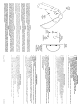
SCREW
TORNILLO
VIS
SCHRAUBEN
VITI
MOUNTING BRACKET
CONSOLA DE MONTAJE
SUPPORT DE FIXATION
HALTERUNG
PIASTRA DI MONTAGGIO
HOUSING
CUBIERTA PROTECTORA
BOÎTER
GEHÄUSE
LAMPADINA
-
 1
1
-
 2
2
-
 3
3
-
 4
4


Kichler Lighting 15066AZT Manuale utente
- Tipo
- Manuale utente
in altre lingue
Documenti correlati
-
 Kichler Lighting 15165AZ Manuale utente
-
 Kichler Lighting 15310AZT Manuale utente
-
Kichler Lighting 15194AZ Manuale utente
-
 Kichler Lighting 15079AZT Manuale utente
-
 Kichler Lighting 15314MST Manuale utente
-
 Kichler Lighting 15317AZT Manuale utente
-
 Kichler Lighting 15313TZG Manuale utente
-
 Kichler Lighting 15318AZT Manuale utente
-
 Kichler Lighting 15323AZT Manuale utente
-
Kichler Lighting 15361AZT Manuale utente


