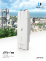
Ubiquiti airFiber 11FX Manuale utente
- Categoria
- Networking
- Tipo
- Manuale utente

11 GHz FDD
Licensed Backhaul Radio
Model: AF-11FX


i
Table of ContentsairFiber AF-11FX User Guide
Ubiquiti Networks, Inc.
Table of Contents
Chapter 1: Overview ................................................1
Introduction. . . . . . . . . . . . . . . . . . . . . . . . . . . . . . . . . . . . . . . . . . . . . . . . . . . . . . . . . . . . . . . . . . . . . . 1
Package Contents ................................................................1
airFiber Configuration Interface System Requirements ............................1
Hardware Overview ..............................................................1
Chapter 2: Installation ..............................................5
Installation Requirements ........................................................5
Installation Overview .............................................................5
Installing the Duplexer for SISO Mode .............................................5
Installing an Optional Duplexer (MIMO Mode) .....................................6
Connecting Power over Ethernet ..................................................7
airFiber Configuration ............................................................8
Hardware Installation .............................................................9
Connecting Power ...............................................................11
Alignment ......................................................................12
Installer Compliance Responsibility ..............................................13
Chapter 3: Navigation .............................................15
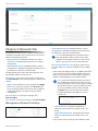
Accessing the airFiber Configuration Interface ...................................15
Interface Pages ..................................................................16
Configuration Interface Notifications .............................................16
Product Verification .............................................................16
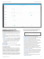
Chapter 4: Dashboard .............................................17
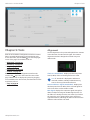
Link Status ......................................................................17
Signal Strength ..................................................................18
Device ..........................................................................18
Ethernet. . . . . . . . . . . . . . . . . . . . . . . . . . . . . . . . . . . . . . . . . . . . . . . . . . . . . . . . . . . . . . . . . . . . . . . . .19
Chapter 5: Wireless Tab ............................................21
Basic Wireless Settings ...........................................................21
Frequency Settings ..............................................................22
Wireless Security ................................................................22
Advanced Wireless Settings ......................................................23
Chapter 6: Network Tab ...........................................25
Management Network Settings ..................................................25
Data Port Ethernet Settings ......................................................26
Ethernet Carrier Drop Settings ...................................................27

ii
Table of Contents airFiber AF-11FX User Guide
Ubiquiti Networks, Inc.
Chapter 7: Services Tab ............................................29
Ping Watchdog ..................................................................29
SNMP Agent. . . . . . . . . . . . . . . . . . . . . . . . . . . . . . . . . . . . . . . . . . . . . . . . . . . . . . . . . . . . . . . . . . . . .30
Web Server ......................................................................30
SSH Server ......................................................................30
Telnet Server ....................................................................30
NTP Client .......................................................................31
Dynamic DNS ...................................................................31
System Log ......................................................................31
Device Discovery ................................................................31
Chapter 8: System Tab .............................................33
Firmware Update ................................................................33
Device ..........................................................................34
Date Settings ....................................................................34
System Accounts ................................................................34
Location ........................................................................34
Device Maintenance .............................................................34
Chapter 9: Tools ...................................................37
Alignment. . . . . . . . . . . . . . . . . . . . . . . . . . . . . . . . . . . . . . . . . . . . . . . . . . . . . . . . . . . . . . . . . . . . . . .37
Discovery .......................................................................38
Ping .............................................................................38
Traceroute ......................................................................38
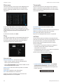
airView ..........................................................................38
Log .............................................................................40
Appendix J: Specifications .........................................41
Appendix K: Safety Notices ........................................43
Electrical Safety Information .....................................................43
Appendix L: Warranty .............................................45
Limited Warranty ................................................................45
Appendix M: Compliance Information .............................47
Installer Compliance Responsibility ..............................................47
Operating License ...............................................................47
FCC .............................................................................47
Frequency Plan ..................................................................47
RF Exposure Warning ............................................................47
Australia and New Zealand ......................................................47
CE Marking ......................................................................47
Compliance Documentation .....................................................47
RoHS/WEEE Compliance Statement ..............................................48

iii
Table of ContentsairFiber AF-11FX User Guide
Ubiquiti Networks, Inc.
Appendix N: Declaration of Conformity ............................49
Appendix O: Contact Information .................................51
Ubiquiti Networks Support ......................................................51

iv
Table of Contents airFiber AF-11FX User Guide
Ubiquiti Networks, Inc.

1
Chapter 1: OverviewairFiber AF-11FX User Guide
Ubiquiti Networks, Inc.
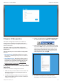
Chapter 1: Overview
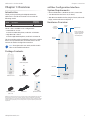
Introduction
Thank you for purchasing the Ubiquiti Networks®
airFiberAF-11FX. This User Guide is for use with the
following model:
Model Description
Operating
Frequency
AF-11FX 11 GHz FDD Licensed Backhaul Radio 10.7 - 11.7 GHz
The AF-11FX is available in two configurations:
• Low-Band: AF-11-FX-L
Includes Low-Band Duplexer, model AF-11FX-DUP-L
• High-Band: AF-11FX-H
Includes High-Band Duplexer, model AF-11FX-DUP-H
This User Guide provides installation instructions, explains
how to set up an airFiber link, and shows how to access
and use the airFiber Configuration Interface.
Note: Throughout this User Guide, airFiber X radio
refers to the model listed above.
Package Contents
Low-Band Duplexer
or
airFiber AF-11FX High-Band Duplexer Cable Ties
(Qty. 2)
11 GHz FDD
Licensed Backhaul Radio
Model: AF-11FX
airFiber Gigabit PoE
(50V, 1.2A)
Power Cord Quick Start Guide
TERMS OF USE: Ubiquiti radio devices must be professionally installed. Shielded Ethernet cable and
earth grounding must be used as conditions of product warranty. TOUGHCable
™
is designed for
outdoor installations. It is the customer’s responsibility to follow local country regulations, including
operation within legal frequency channels, output power, and Dynamic Frequency Selection (DFS)
requirements.
airFiber Configuration Interface
System Requirements
• Microsoft Windows 7, Windows 8; Linux; or Mac OS X
• Java Runtime Environment 1.6 (or above)
• Web Browser: Mozilla Firefox, Google Chrome, Microsoft
Edge, or Microsoft Internet Explorer 11
Hardware Overview
Captive
Screw
Duplexer Cap*
* Chain 1 (Under Cap)
Connects to Antenna
(Requires Optional
Second Duplexer)
Chain 0:
Connects to
Antenna
Duplexer
Shroud
LED Panel
Port Cover

2
Chapter 1: Overview airFiber AF-11FX User Guide
Ubiquiti Networks, Inc.
Ports
Management
Port
Reset
Button
Data
Port
VDC IN
50V 1.2A
Management Port 10/100 Mbps, secured Ethernet
port for configuration. In-Band Management is enabled
by default in the airFiber Configuration Interface. When
In-Band Management is disabled, the MGMT port is the
only port that can monitor, configure, and/or update
firmware.
Reset Button To reset to factory defaults, press and hold
the Reset button for more than 10 seconds while the
device is powered on.
Data Port Gigabit PoE port for handling all user traffic
and powering the device.
VDC IN The terminal block can be used to power the
AF-11FX with +50VDC 1.2A DC power instead of PoE.
Duplexer Ports
TX 0 RX 0 RX 1 TX 1
TX 0
Top View
of AF-11FX
(Duplexer
Shroud
Removed)
RX 0 RX 1 TX 1
TX 0, RX 0 The TX and RX SMA ports for the Chain 0
Low-Band Duplexer or High-Band Duplexer (SISO and MIMO
modes).
RX 1, TX 1 The RX and TX SMA ports for the Chain 1
Low-Band Duplexer or High-Band Duplexer (MIMO mode
only). In SISO mode, these unused ports are protected by
the Duplexer Cap.
Duplexer
SMA Ports
N Connector
Low-Band
Duplexer
High-Band
Duplexer
N Connector Female N-type connector into which the
antenna cable is plugged.
SMA Ports High-band and low-band channel SMA ports.
LEDs
Signal LEDs
Signal 4 LED will light blue when on.
Signal 3 LED will light green when on.
Signal 2 LED will light yellow when on.
Signal 1 LED will light red when on.
Bootup to airOS When powering on, the Power, MIMO,
LINK, and Signal 1-4 LEDs light on. Once the CPU code
takes over, the MIMO, LINK, and Signal 1-3 LEDs turn off.
The Signal 4 LED remains lit to indicate the boot sequence
is underway.
Initializing airFiber Software When the airFiber
application begins to boot under airOS, the Signal 4 LED
goes from solidly on to a 2.5 Hz flash. This continues until
the AF-11FX radio is fully booted.
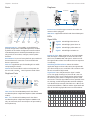
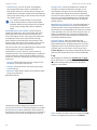
Signal Level Once fully booted, the Signal 1-4 LEDs
act as a bar graph showing how close the AF-11FX is to
ideal aiming. This is auto-scaled based on the link range,
the antenna gains, and the configured TX power of the
remote AF-11FX. Each Signal LED has three possible states:
On, Flashing, and Off. All Signal LEDs would be solidly on
in an ideal link. For example, if the link has a 1 dB loss, the
Signal4 LED will flash; a 2 dB loss and the Signal 4 LED will
turn off. The full bar graph LED states are shown below.
dB
loss
0 -1 -2 -3 -4 -5 -6 -7 -8 -9 -10 -11 -12 -13
1 F 0 0 0 0 0 0 0 0 0 0 0 0
1 1 1 F 0 0 0 0 0 0 0 0 0 0
1 1 1 1 1 F F 0 0 0 0 0 0 0
1 1 1 1 1 1 1 1 1 1 F F F 0
0 = Off, 1 = On, F = Flashing

3
Chapter 1: OverviewairFiber AF-11FX User Guide
Ubiquiti Networks, Inc.
Additional LEDs
LED State Status
LINK
Off RF Off
Short Flash* Syncing
Normal Flash* Beaconing
Long Flash* Registering
On Operational
MIMO
Off Radio configured in SISO Mode
On Radio configured in MIMO Mode
MGMT
Off No Ethernet Link
On Ethernet Link Established
Random Flashing Ethernet Activity
DATA
Off No Ethernet Link
On Ethernet Link Established
Random Flashing Ethernet Activity
Off No Power
On Powered On
* Short Flash (1:3 on/off cycle)
Normal Flash (1:1 on/off cycle)
Long Flash (3:1 on/off cycle)

4
Chapter 1: Overview airFiber AF-11FX User Guide
Ubiquiti Networks, Inc.

5
Chapter 2: InstallationairFiber AF-11FX User Guide
Ubiquiti Networks, Inc.
Chapter 2: Installation
Installation Requirements
The airFiberAF‑11FX radio is designed for use with the
airFiber X antenna model AF‑11G35. (Check your local/
regional regulations for the allowable antenna gain
allowed for your application.)
See the antenna’s Quick Start Guide for antenna
installation instructions.
Other Requirements
• Clear line of sight between airFiberX radios
• Vertical mounting orientation
• Mounting point:
• At least 1 m below the highest point on the structure
• For tower installations, at least 3 m below the top of
thetower
• Ground wires – min. 10 AWG (5 mm
2
) and max. length:
1m. Asa safety precaution, ground the airFiberX radio
to grounded masts, poles, towers, or grounding bars.
WARNING: Failure to properly ground your
airFiberX radio will void your warranty.
• (Recommended) 2 Outdoor Gigabit PoE surge protectors
Note: For guidelines about grounding and
lightning protection, follow your local electrical
regulatory codes.
• (Optional) For MIMO mode operation: A second
Duplexer of the same type as the one included with the
AF‑11FX radio:
• High-Band Duplexer (model AF‑11FX‑DUP‑H) or
• Low-Band Duplexer (model AF‑11FX‑DUP‑L)
• (Optional) If not using PoE: DC power source and
12/30AWG power cable.
• Outdoor, shielded Category 6 (or above) cabling and
shielded RJ‑45 connectors are required for all wired
Ethernet connections.
Installation Overview
We recommend to configure your paired AF‑11FX radios
before site installation. The overview below summarizes
the installation procedure, and the subsequent sections
provide detailed installation information:
• Install the Duplexer(s) in the AF‑11FX radio.
• Connect the airFiber Gigabit PoE adapter to the DATA
port, and connect your computer to the MGMTport.
• Configure the AF‑11FX.
• Install a ground wire and mount the AF‑11FX on the
airFiber AF‑11G35 antenna (or a compatible antenna).
• At the installation site, install the antenna with the
mounted AF‑11FX radio (see the antenna’s Quick Start
Guide for installation instructions).
• Connect the DATA port to your LAN, and connect power
(PoE or DC power) to the AF‑11FX.
• Establish and optimize the RF link..
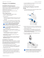
Installing the Duplexer for SISO
Mode
1. Loosen the Captive Screw on top of the Duplexer Shroud
and remove the Duplexer Shroud.
Dust
Covers
Duplexer
Shroud
2. Remove the Dust Covers from the TX0 and RX0 ports of
the AF‑11FX radio. Do not remove the Dust Covers from
the RX1 and TX1 ports.
3. Seat the SMA Ports of the Duplexer onto the TX0 and
RX0 ports of the AF‑11FX, while positioning the Low
Channel and High Channel ports to yield the required
transmit and receive frequencies.
4. Secure the Duplexer to the radio by tightening the
collars on the SMA Ports.
WARNING: Tighten the collars alternately, turning
one collar a half turn, then the other a half turn,
and so on, until both are fully tightened. Failure to
do so may result in damage to the Duplexer.

6
Chapter 2: Installation airFiber AF-11FX User Guide
Ubiquiti Networks, Inc.
5. Reseat the Duplexer Shroud onto the AF‑11FX radio
and tighten the Captive Screw to secure the Duplexer
Shroud.
6. Repeat steps 1‑4 for the radio to be used on the other
end of the link, ensuring that the numbers on the
second radio’s Duplexer are in the reverse order of the
numbers on first radio’s Duplexer.
Note: For example, if the numbers on the first
radio’s Duplexer are (left to right) 1/3, then the
numbers on the second radio’s Duplexer should
be 3/1.
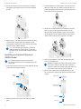
Installing an Optional Duplexer
(MIMO Mode)
Note: MIMO operation requires two licenses,
one per polarization and a second Duplexer of the
same band.
1. Loosen the Captive Screw on top of the Duplexer Shroud
and remove the Duplexer Shroud.
Dust
Covers
Duplexer
Shroud
2. Remove the Dust Covers from the radio’s four SMA
ports.
3. Seat the SMA Ports of one Duplexer onto the TX0 and
RX0 ports of the AF‑11FX, while positioning the Low
Channel and High Channel ports to yield the required
transmit and receive frequencies.
4. Attach the second Duplexer (not included) to the RX1
and TX1 ports, ensuring that the numbers on the
adjacent sides of the Duplexers match. (The numbers
on the Duplexer on the right should be in the reverse
order of the numbers on the Duplexer on the left.)
5. Secure each Duplexer to the radio by tightening the
collars on the SMA Ports.
WARNING: Tighten the collars alternately, turning
one collar a half turn, then the other a half turn,
and so on, until both are fully tightened. Failure to
do so may result in damage to the Duplexer.
6. Remove the Duplexer Cap and Cap Washer from the
AF‑11FX by removing the Cap Screw located inside the
shroud.
Cap Screw
Cap Washer
Duplexer Cap
Duplexer Shroud
(side view)

7
Chapter 2: InstallationairFiber AF-11FX User Guide
Ubiquiti Networks, Inc.
7. Reseat the Duplexer Shroud onto the AF‑11FX radio
and tighten the Captive Screw to secure the Duplexer
Shroud.
8. Repeat steps 1‑7 for the other radio to be used in the
link, ensuring that the numbers on the second radio’s
Duplexers are in the reverse order of the numbers on
the first radio’s Duplexers.
Note: For example, if the numbers on the first
radio’s Duplexers are (left to right) 1/3 and 3/1,
then the numbers on the second radio’s Duplexers
should be 3/1 and 1/3.
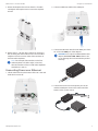
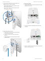
Connecting Power over Ethernet
1. Lift the release latch on the bottom of the AF‑11FX and
slide the Port Cover off.
2. Connect an Ethernet cable to the DATA port.
3. Connect the Ethernet cable from the DATA port of the
AF‑11FX to the POE port of the adapter.
WARNING: Use only the included airFiber PoE
adapter, Model GP-C500-120G. Failure to do
so can damage the unit and void the product
warranty.
4. Connect the Power Cord to the power port on the
airFiber PoE Adapter. Connect the other end of the
Power Cord to a powersource.

8
Chapter 2: Installation airFiber AF-11FX User Guide
Ubiquiti Networks, Inc.
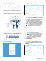
airFiber Configuration
The instructions in this section explain how to access
the airFiber Configuration Interface and configure the
following settings:
• Wireless Mode Configure one AF‑11FX radio as the
Master and the other as the Slave.
• Frequency Setting The TX Frequency and RX Frequency
must be the reverse of each other on both the Master
and the Slave.
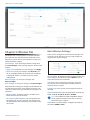
1. Connect an Ethernet cable from your computer to the
MGMT port on the AF‑11FX radio.
2. Configure the Ethernet adapter on your computer with
a static IP address on the 192.168.1.x subnet.
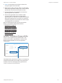
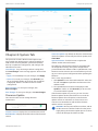
3. Launch your web browser. Type http://192.168.1.20 in
the address field and press enter (PC) or return (Mac).
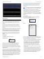
4. The login screen will appear. Enter ubnt in the
Username and Password fields. Select your Country and
Language. You must agree to the Terms of Use to use
the product. Click Login.
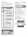
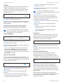
5. Click Settings, and then click the Wireless tab.
6. Configure the Basic Wireless Settings:
a. For one AF‑11FX, select Master as the Wireless Mode.
For the other AF‑11FX radio, keep the default,Slave.
b. Enter a name in the Link Name field. This should be
the same on both the Master and the Slave.
c. If needed, change the Channel Bandwidth, Output
Power, and/or Maximum Modulation Rate settings.
7. Configure the TX Frequency Setting and RX Frequency.
Note: One airFiberX radio’s TX Frequency is the
other radio’s RX Frequency, and vice versa.
8. Configure the Wireless Security:
a. Select the Key Type, HEX or ASCII.
b. For the Key field:
‑ HEX Enter 16 bytes (eight, 16‑bit hexadecimal
digits: 0‑9, A‑F, or a‑f ). You can omit zeroes and
use colons, similar to the IPv6 format.
Note: The airFiber Configuration Interface
supports IPv6 formats excluding dotted
quad and “::” (double‑colon) notation.
‑ ASCII Enter a combination of alphanumeric
characters (0‑9, A‑Z, or a‑z).
9. Click Save Changes.
10. In-Band Management is enabled by default, so each
AF‑11FX radio must have a unique IP Address. (If the
AF‑11FX radios use the same IP Address, you may
lose access to the radios via the DATA ports.) Click the
Network tab.

9
Chapter 2: InstallationairFiber AF-11FX User Guide
Ubiquiti Networks, Inc.
a. For the Management IP Address option:
‑ DHCP Keep the default, DHCP, to use DHCP
reservation on your router to assign a unique
IPAddress.
‑ Static Change the IP Address, Netmask, and other
settings to make them compatible with your
network.
b. Click Save Changes.
11. Disconnect the Ethernet cables from the MGMT and
DATA ports on the AF‑11FX. Configuration of the
AF‑11FX radio is complete.
Repeat the instructions in the airFiber Configuration
section on the other AF‑11FX radio.
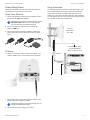
Hardware Installation
Install a Ground Wire
1. Remove the nut from the Ground Bonding Point located
on the back of the AF‑11FX, near the lower‑right corner.
Ground
Bonding
Point
2. Attach a ground wire (min. 10 AWG or 5 mm
2
) to the
lug and replace the nut to secure the wire.
3. At the installation site, secure the other end of the
ground wire to a grounded mast, pole, tower, or
grounding bar.
WARNING: Failure to properly ground your
airFiberXradio will void your warranty.
Note: The ground wire should be as short as
possible and no longer than one meter in length.
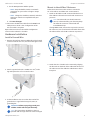
Mount to the airFiberX Antenna
Follow the instructions in this section to mount the
AF‑11FX radio to an airFiberX AF‑11G35 antenna:
1. Attach an RF Cable to an RF connector labeled H or V.
Then slide the silicone boot over the RF connector to
protect it.
Note: For SISO mode, use the RF connector
(HorV) as determined by your licensing. Keep
the other RF connector covered with the
included Metal Cap.
If using MIMO mode, remove the cap over the second
RF connector (V or H) and attach an RF Cable. Then slide
the silicone boot over the RF connector to protect it.
H Connector
V Connector
2. Attach the AF‑11FX radio to the antenna by aligning
the four tabs on the back of the radio with the slots of
the radio mount. Then slide the radio down to lock it
into place.

10
Chapter 2: Installation airFiber AF-11FX User Guide
Ubiquiti Networks, Inc.
3. Connect the RF Cable(s) (one in SISO mode, two in
MIMO mode) to the radio as follows:
• Attach the RF Cable from the H Connector to the
radio’s Chain 0 connector.
• Attach the RF Cable from the V Connector to the
radio’s Chain 1 connector.
V Connector
H Connector
Chain 1
Chain 0
4. Attach the protective shroud.
a. Align the dot on the top of the shroud with the
arrow on the dish antenna.
b. Guide the shroud’s tabs into the slots on the
antenna.
c. Push the shroud in and then pull it down until it
locks into place.
Dot
Arrow
Connecting Data
1. Lift the release latch on the bottom of the AF‑11FX and
slide the Port Cover off.
2. Connect an outdoor, shielded Ethernet cable to the
DATA port.
3. If you are using DC power, connect the other end of the
Ethernet cable to yourLAN.

11
Chapter 2: InstallationairFiber AF-11FX User Guide
Ubiquiti Networks, Inc.
Connecting Power
Follow the instructions for the source of power that you
are using: Power over Ethernet or DC Power.
Power Over Ethernet
1. Connect the Ethernet cable from the DATA port of the
AF‑11FX to the POE of the adapter.
WARNING: Use only the included adapter, model
GP-C500-120G. Failure to do so can damage
the unit and void the product warranty.
2. Connect an Ethernet cable from your LAN to the
adapter’s LAN port.
3. Connect the Power Cord to the adapter’s power port.
Connect the other end of the Power Cord to a power
outlet.
DC Power
1. Connect a DC power cable to the Terminal Block. (The
+VDC and GND can be connected to either terminal.)
2. Connect the other end of the DC power cable to a DC
power supply that supplies +50VDC.
WARNING: Applying a negative voltage such as
‑48VDC will damage the radio.
3. Connect the DC power supply to its source.
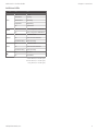
Surge Protection
For added protection, install two surge suppressors, such
as the Ubiquiti Ethernet Surge Protector, model ETH‑SP,
at the end of each link. Install the first surge protector
within one meter of the airFiber DATA port, and install the
second surge protector at the ingress point of the location
housing the wired network equipment.
Ground to Pole, Tower,
or Grounding Block:
Max. 1 m from AF-11FX
Max. 1 m
airFiber PoE Adapter
EdgeRouter
™
Power Source
ETH-SP
ETH-SP
AF-11FX
Mounted on
AF-11G35

12
Chapter 2: Installation airFiber AF-11FX User Guide
Ubiquiti Networks, Inc.
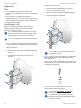
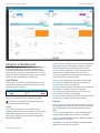
Alignment
Tips
• To accurately align the airFiberX radios for best
performance, you MUST align only one end of the link at
a time.
• You may need to use additional hardware to
compensate for issues such as the improper orientation
of a mounting pole or significant elevation differences
between airFiberX radios.
Establishing a Link
Adjust the positions of the Master and the Slave to
establish a link. The following section features the
airFiberX antenna, AF‑11G35.
Note: The Master must be aimed first at the Slave
because the Slave does not transmit any RF signal
until it detects transmissions from the Master.
Note: For complete details on the antenna, refer to
the Quick Start Guide for your specific model.
1. Master Visually aim the Master at the Slave. To adjust
the Master’s position, adjust the azimuth and elevation:
Adjust the azimuth:
a. Loosen the four flange nuts on the two pole clamps.
b. Rotate the antenna to point towards the other end
of the link.
c. Tighten the four flange nuts on the two pole
clamps.
Adjust the elevation angle:
a. Loosen the eight hex head bolts to so that the
washers can spin freely by hand.
b. Tighten or loosen the Elevation Adjustment Bolt to
set the desired tilt.
c. Tighten the eight hex head bolts.
Note: Do NOT make simultaneous adjustments
on the Master and Slave.
2. Slave Visually aim the Slave at the Master. To adjust the
Slave’s position, adjust the azimuth and elevation as
described in step 1.
3. Check to see if a link is established. Ensure that the LINK
LED is solidly lit green and the Signal LEDs of the Slave
are displaying signal levels.
4. Slave Aim the Slave at the Master to achieve the
strongest signal level on the Master.
Note: Refer to “Signal LEDs” on page 2 for
details on the signal values.
Note: Maximum signal strength can best be
achieved by iteratively sweeping through both
azimuth and elevation.

13
Chapter 2: InstallationairFiber AF-11FX User Guide
Ubiquiti Networks, Inc.
5. Master Aim the Master at the Slave to achieve the
strongest signal level on the Slave.
6. Repeat steps 4 and 5 until you achieve an optimal link,
with all four Signal LEDs solidly lit. This ensures the best
possible data rate between the airFiberX radios.
7. Lock the alignment on both airFiberX antennas by
tightening all the nuts and bolts.
8. Observe the Signal LEDs of each airFiberX radio
to ensure that the values remain constant while
tightening the nuts and bolts. If any LED value changes
during the locking process, loosen the nuts and bolts,
finalize the alignment of each airFiberX antenna again,
and retighten the nuts and bolts.
Refer to the following chapters of this User Guide for
details on the airFiber Configuration Interface:
• “Dashboard” on page 17
• “Wireless Tab” on page 21
• “Network Tab” on page 25
• “Services Tab” on page 29
• “System Tab” on page 33
• “Tools” on page 37
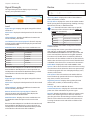
Installer Compliance Responsibility
Devices must be professionally installed and it is the
professional installer’s responsibility to make sure the
device is operated within local country regulatory
requirements.
The Output Power, Antenna Gain, Cable Loss*, TXFrequency,
and RXFrequency fields are provided to the professional
installer to assist in meeting regulatory requirements.
* Cable Loss includes loss due to the Duplexer(s).

14
Chapter 2: Installation airFiber AF-11FX User Guide
Ubiquiti Networks, Inc.
La pagina si sta caricando...
La pagina si sta caricando...
La pagina si sta caricando...
La pagina si sta caricando...
La pagina si sta caricando...
La pagina si sta caricando...
La pagina si sta caricando...
La pagina si sta caricando...
La pagina si sta caricando...
La pagina si sta caricando...
La pagina si sta caricando...
La pagina si sta caricando...
La pagina si sta caricando...
La pagina si sta caricando...
La pagina si sta caricando...
La pagina si sta caricando...
La pagina si sta caricando...
La pagina si sta caricando...
La pagina si sta caricando...
La pagina si sta caricando...
La pagina si sta caricando...
La pagina si sta caricando...
La pagina si sta caricando...
La pagina si sta caricando...
La pagina si sta caricando...
La pagina si sta caricando...
La pagina si sta caricando...
La pagina si sta caricando...
La pagina si sta caricando...
La pagina si sta caricando...
La pagina si sta caricando...
La pagina si sta caricando...
La pagina si sta caricando...
La pagina si sta caricando...
La pagina si sta caricando...
La pagina si sta caricando...
La pagina si sta caricando...
La pagina si sta caricando...
-
 1
1
-
 2
2
-
 3
3
-
 4
4
-
 5
5
-
 6
6
-
 7
7
-
 8
8
-
 9
9
-
 10
10
-
 11
11
-
 12
12
-
 13
13
-
 14
14
-
 15
15
-
 16
16
-
 17
17
-
 18
18
-
 19
19
-
 20
20
-
 21
21
-
 22
22
-
 23
23
-
 24
24
-
 25
25
-
 26
26
-
 27
27
-
 28
28
-
 29
29
-
 30
30
-
 31
31
-
 32
32
-
 33
33
-
 34
34
-
 35
35
-
 36
36
-
 37
37
-
 38
38
-
 39
39
-
 40
40
-
 41
41
-
 42
42
-
 43
43
-
 44
44
-
 45
45
-
 46
46
-
 47
47
-
 48
48
-
 49
49
-
 50
50
-
 51
51
-
 52
52
-
 53
53
-
 54
54
-
 55
55
-
 56
56
-
 57
57
-
 58
58


Ubiquiti airFiber 11FX Manuale utente
- Categoria
- Networking
- Tipo
- Manuale utente
in altre lingue
- English: Ubiquiti airFiber 11FX User manual
Documenti correlati
-
Ubiquiti airFiber AF-24 Manuale utente
-
Ubiquiti AF-5G23-S45 Guida Rapida
-
-
-
Ubiquiti ERLite-3 Guida Rapida
-
-
Ubiquiti Networks Pico Manuale utente
-
Ubiquiti EdgeRouter X ER-X Guida Rapida
-
-

