Asus RS520A-E12-RS24U Manuale utente
- Categoria
- Schede madri
- Tipo
- Manuale utente

2U Rackmount Server
User Guide
RS520A-E12 Series
RS520A-E12-RS24U

ii
Copyright © 2023 ASUSTeK COMPUTER INC. All Rights Reserved.
No part of this manual, including the products and software described in it, may be reproduced, transmitted,
transcribed, stored in a retrieval system, or translated into any language in any form or by any means,
except documentation kept by the purchaser for backup purposes, without the express written permission
of ASUSTeK COMPUTER INC. (“ASUS”).
ASUS provides this manual “as is” without warranty of any kind, either express or implied, including but not
limited to the implied warranties or conditions of merchantability or fitness for a particular purpose. In no
event shall ASUS, its directors, officers, employees, or agents be liable for any indirect, special, incidental,
or consequential damages (including damages for loss of profits, loss of business, loss of use or data,
interruption of business and the like), even if ASUS has been advised of the possibility of such damages
arising from any defect or error in this manual or product.
Specifications and information contained in this manual are furnished for informational use only, and are
subject to change at any time without notice, and should not be construed as a commitment by ASUS.
ASUS assumes no responsibility or liability for any errors or inaccuracies that may appear in this manual,
including the products and software described in it.
Product warranty or service will not be extended if: (1) the product is repaired, modified or altered, unless
such repair, modification of alteration is authorized in writing by ASUS; or (2) the serial number of the
product is defaced or missing.
Products and corporate names appearing in this manual may or may not be registered trademarks or
copyrights of their respective companies, and are used only for identification or explanation and to the
owners’ benefit, without intent to infringe.
E21818
Revised Edition V3
March 2023

iii
Contents
Safety information ..................................................................................................... vii
About this guide ......................................................................................................... ix
1.1 System package contents ......................................................................... 1-2
1.2 Serial number label .................................................................................... 1-3
1.3 System specifications ...............................................................................1-4
1.4 Front panel features ...................................................................................1-7
1.5 Rear panel features ....................................................................................1-8
1.6 Internal features .........................................................................................1-9
1.7 LED information .......................................................................................1-10
1.7.1 Front panel LEDs ...................................................................... 1-10
1.7.2 Storage device status LED........................................................ 1-11
1.7.3 LAN (RJ-45) LEDs .................................................................... 1-11
1.7.4 Rear panel LEDs ....................................................................... 1-12
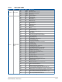
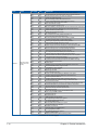
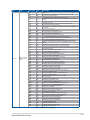
1.7.5 Q-Code table ............................................................................. 1-13
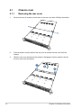
2.1 Chassis cover .............................................................................................2-2
2.1.1 Removing the rear cover ............................................................. 2-2
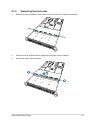
2.1.2 Removing the mid cover ............................................................. 2-3
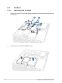
2.2 Air duct........................................................................................................2-4
2.2.1 Removing the air ducts ............................................................... 2-4
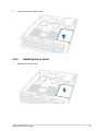
2.2.2 Installing the air ducts ................................................................. 2-5
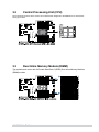
2.3 Central Processing Unit (CPU) .................................................................2-7
2.3.1 Installing the CPU and heatsink .................................................. 2-7
2.4 System memory .......................................................................................2-11
2.4.1 Overview ................................................................................... 2-11
2.4.2 Memory Configurations ............................................................. 2-11
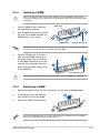
2.4.3 Installing a DIMM ...................................................................... 2-13
2.4.4 Removing a DIMM .................................................................... 2-13
2.5 (optional) Front bezel ...............................................................................2-14
2.5.1 Removing the front bezel .......................................................... 2-14
2.5.2 Installing the front bezel ............................................................ 2-15
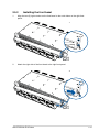
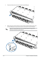
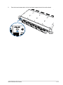
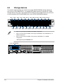
2.6 Storage devices........................................................................................2-18
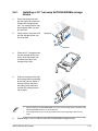
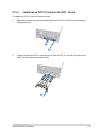
2.6.1 Installing a 2.5” hot-swap SATA/SAS/NVMe storage device .... 2-19
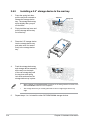
2.6.2 Installing a 2.5” storage device to the rear bay ......................... 2-20

iv
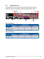
2.7 Expansion slot ..........................................................................................2-21
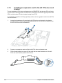
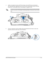
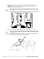
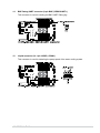
2.7.1 Installing an expansion card to the left PCIe riser card bracket 2-22
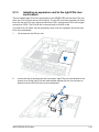
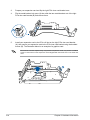
2.7.2 Installing an expansion card to the right PCIe riser card bracket 2-25
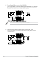
2.7.3 Installing an HBA/RAID card to the right PCIe riser card bracket 2-29
2.7.4 Installing an OCP 3.0 card to the OCP 3.0 slot ......................... 2-31
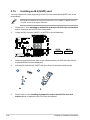
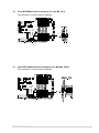
2.7.5 Installing an M.2 (NGFF) card ................................................... 2-32
2.7.6 (optional) Installing the PFR module ......................................... 2-33
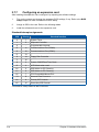
2.7.7 Configuring an expansion card ................................................. 2-34
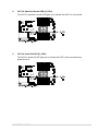
2.8 Cable connections ...................................................................................2-35
2.9 Backplane cabling ...................................................................................2-36
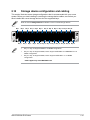
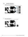
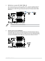
2.10 Storage device configuration and cabling ............................................2-37
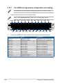
2.10.1 24 x NVMe storage device configuration and cabling .............. 2-38
2.10.2 16 x NVMe and 8 x SAS/SATA storage device configuration
and cabling ................................................................................ 2-39
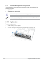
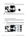
2.11 Removable/optional components ...........................................................2-40
2.11.1 System fans .............................................................................. 2-40
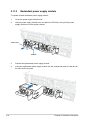
2.11.2 Redundant power supply module.............................................. 2-42
2.12 Rail Kit Options ........................................................................................2-43
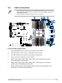
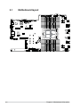
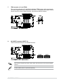
3.1 Motherboard layout ....................................................................................3-2
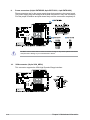
3.2 Central Processing Unit (CPU) .................................................................3-5
3.3 Dual Inline Memory Module (DIMM) ..........................................................3-5
3.4 Jumpers ......................................................................................................3-6
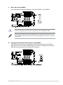
3.5 Internal LEDs ............................................................................................ 3-11
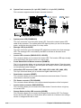
3.6 Internal connectors ..................................................................................3-14
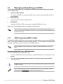
4.1 Managing and updating your BIOS ..........................................................4-2
4.1.1 ASUS CrashFree BIOS 3 utility................................................... 4-2
4.1.2 ASUS EZ Flash Utility ................................................................. 4-3
4.1.3 BUPDATER utility ....................................................................... 4-4
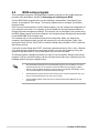
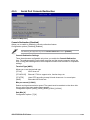
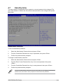
4.2 BIOS setup program ..................................................................................4-6
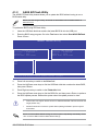
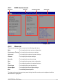
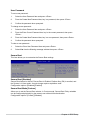
4.2.1 BIOS menu screen ...................................................................... 4-7
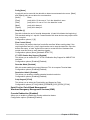
4.2.2 Menu bar ..................................................................................... 4-7
4.2.3 Menu items..................................................................................4-8
4.2.4 Submenu items ........................................................................... 4-8
4.2.5 Navigation keys ........................................................................... 4-8
4.2.6 General help................................................................................4-8
4.2.7 Configuration fields ..................................................................... 4-8
4.2.8 Pop-up window............................................................................4-8
4.2.9 Scroll bar ..................................................................................... 4-8
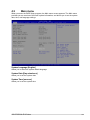
4.3 Main menu ..................................................................................................4-9
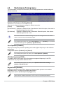
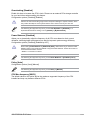
4.4 Performance Tuning menu ......................................................................4-10

v
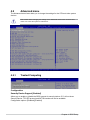
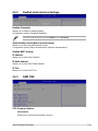
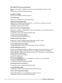
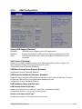
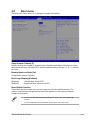
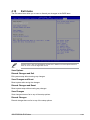
4.5 Advanced menu .......................................................................................4-12
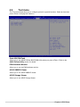
4.5.1 Trusted Computing.................................................................... 4-12
4.5.2 Redfish Host Interface Settings................................................. 4-13
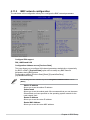
4.5.3 AMD CBS .................................................................................. 4-13
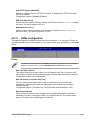
4.5.4 Onboard LAN Configuration ...................................................... 4-22
4.5.5 Serial Port Console Redirection ................................................ 4-23
4.5.6 CPU Configuration .................................................................... 4-25
4.5.7 PCI Subsystem Settings ........................................................... 4-26
4.5.8 USB Configuration .................................................................... 4-31
4.5.9 Network Stack Configuration..................................................... 4-32
4.5.10 NVMe Configuration .................................................................. 4-33
4.5.11 SATA Configuration .................................................................. 4-34
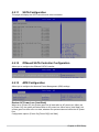
4.5.12 Offboard SATA Controller Configuration ................................... 4-34
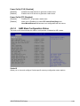
4.5.13 APM Configuration .................................................................... 4-34
4.5.14 AMD Mem Configuration Status................................................ 4-35
4.5.15 T1s Auth .................................................................................... 4-36
4.5.16 Driver Health ............................................................................. 4-36
4.5.17 Third-party UEFI driver configurations ...................................... 4-37
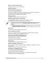
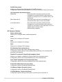
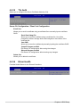
4.6 Chipset menu ...........................................................................................4-38
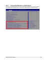
4.7 Security menu ..........................................................................................4-39
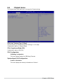
4.8 Boot menu ................................................................................................4-43
4.9 Tool menu ................................................................................................. 4-44
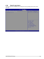
4.10 Event Logs menu .....................................................................................4-45
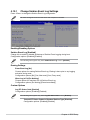
4.10.1 Change Smbios Event Log Settings ......................................... 4-46
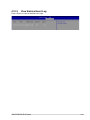
4.10.2 View Smbios Event Log ............................................................ 4-47
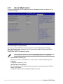
4.11 Server Mgmt menu ...................................................................................4-48
4.11.1 System Event Log ..................................................................... 4-49
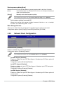
4.11.2 BMC network configuration ....................................................... 4-50
4.11.3 View System Event Log ............................................................ 4-52
4.12 Exit menu .................................................................................................. 4-53
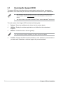
5.1 Running the Support DVD .........................................................................5-2
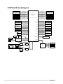
K14PA-U24 block diagram ..................................................................................... A-2
Notices .................................................................................................................... A-3
Service and Support ............................................................................................... A-7

vi

vii
Safety information
Electrical Safety
• Before installing or removing signal cables, ensure that the power cables for the system
unit and all attached devices are unplugged.
• To prevent electrical shock hazard, disconnect the power cable from the electrical outlet
before relocating the system.
• When adding or removing any additional devices to or from the system, ensure that the
power cables for the devices are unplugged before the signal cables are connected. If
possible, disconnect all power cables from the existing system before you add a device.
• If the power supply is broken, do not try to fix it by yourself. Contact a qualified service
technician or your dealer.
Operation Safety
• Any mechanical operation on this server must be conducted by certified or experienced
engineers.
• Before operating the server, carefully read all the manuals included with the server
package.
• Before using the server, ensure all cables are correctly connected and the power cables
are not damaged. If any damage is detected, contact your dealer as soon as possible.
• To avoid short circuits, keep paper clips, screws, and staples away from connectors,
slots, sockets and circuitry.
• Avoid dust, humidity, and temperature extremes. Place the server on a stable surface.
• If you encounter technical problems with the product, contact a qualified service
technician or your retailer.
This product is equipped with a three-wire power cable and plug for the user’s safety. Use
the power cable with a properly grounded electrical outlet to avoid electrical shock.

viii
Heavy System
CAUTION! This server system is heavy. Ask for assistance when moving
or carrying the system.
Lithium-Ion Battery Warning
CAUTION! Danger of explosion if battery is incorrectly replaced. Replace
only with the same or equivalent type recommended by the manufacturer.
Dispose of used batteries according to the manufacturer’s instructions.
To prevent exposure to the optical drive’s laser, do not attempt to disassemble or repair the
optical drive by yourself. For your safety, contact a professional technician for assistance.
CLASS 1 LASER PRODUCT
Optical Drive Safety Information
Laser Safety Information

ix
About this guide
Audience
This user guide is intended for system integrators, and experienced users with at least basic
knowledge of configuring a server.
Contents
This guide contains the following parts:
1. Chapter 1: Product Introduction
This chapter describes the general features of the server, including sections on front
panel and rear panel specifications.
2. Chapter 2: Hardware Information
This chapter lists the hardware setup procedures that you have to perform when
installing or removing system components.
3. Chapter 3: Motherboard Information
This chapter gives information about the motherboard that comes with the server. This
chapter includes the motherboard layout, jumper settings, and connector locations.
4. Chapter 4: BIOS Setup
This chapter tells how to change system settings through the BIOS Setup menus and
describes the BIOS parameters.
5. Chapter 5: Driver Installation
This chapter provides instructions for installing the necessary drivers for different
system components.

x
References
Refer to the following sources for additional information, and for product and software
updates.
1. ASUS Control Center (ACC) user guide
This manual tells how to set up and use the proprietary ASUS server management
utility. Visit asuscontrolcenter.asus.com for more information.
2. ASUS websites
The ASUS websites provide updated information for all ASUS hardware and software
products. Visit https://www.asus.com for more information.
Conventions
To ensure that you perform certain tasks properly, take note of the following symbols used
throughout this manual.
Typography
Bold text Indicates a menu or an item to select.
Italics
Used to emphasize a word or a phrase.
<Key> Keys enclosed in the less-than and greater-than sign
means that you must press the enclosed key.
Example: <Enter> means that you must press the Enter
or Return key.
<Key1>+<Key2>+<Key3> If you must press two or more keys simultaneously, the
key names are linked with a plus sign (+).
Example: <Ctrl>+<Alt>+<Del>
Command Means that you must type the command exactly as
shown, then supply the required item or value enclosed in
brackets.
Example: At the DOS prompt, type the command line:
format A:/S
DANGER/WARNING: Information to prevent injury to yourself when trying to
complete a task.
CAUTION: Information to prevent damage to the components when
trying to complete a task.
IMPORTANT: Instructions that you MUST follow to complete a task.
NOTE: Tips and additional information to help you complete a task.

This chapter describes the general features of the server. It
includes sections on front panel and rear panel specifications.
1
Product Introduction
Chapter 1: Product Introduction

Chapter 1: Product Introduction
1-2
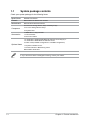
If any of the above items is damaged or missing, contact your retailer.
1.1 System package contents
Check your system package for the following items.
Model Name RS520A-E12-RS24U
Chassis ASUS R2P-E 2U Rackmount Chassis
Motherboard ASUS K14PA-U24 Server Board
Component
24 x 2.5-inch Storage Device Trays or Dummy Trays
2 x 2.5-inch Storage Device Trays
4 x System Fans
Accessories
1x AMD EPYC™ Support DVD
1 x CPU Heatsink
2 x AC Power Cable
Optional Items
1+1 Redundant 1200W/1600W 80PLUS Platinum Power Supply or
1+1 Redundant 1600W 80PLUS Titanium Power
2 x Riser card (16 NVMe configuration & 12 NVMe configuration)
1 x System redundant fan kit
1 x Friction Rail Kit or Ball-bearing rail kit
ASUS PIKE II 3008 card

ASUS RS520A-E12 Series 1-3
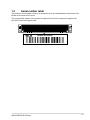
1.2 Serial number label
The product’s serial number contains 12 characters such as xxSxxxxxxxxx and printed on the
sticker at the server's front cover.
The correct serial number of the product is required if you need to request for support from
the ASUS Technical Support team.
xxSxxxxxxxxx
RS520A-E12-RS24U
1 2
3 4
RESET

Chapter 1: Product Introduction
1-4
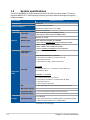
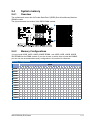
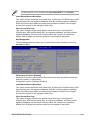
1.3 System specifications
The ASUS RS520A-E12 Series features the ASUS K14PA-U24 server board. The server
supports AMD EPYC™ 9004 Series processors plus other latest technologies through the
chipsets onboard.
(continued on the next page)
Model Name RS520A-E12-RS24U
Motherboard K14PA-U24
Processor Support 1 x Socket SP5 (LGA 6096)
AMD EPYC™ 9004 series (up to 400W)
Core Logic System on Chip (SoC)
Memory
Total Slots 24 (12-channel per CPU, 24 DIMM per CPU)
* May support to 2DPC, depends on AMD schedule
Capacity Maximum up to 6TB
Memory Type DDR5 4800/4400 RDIMM / 3DS RDIMM
* Please refer to www.asus.com for latest memory AVL update
Memory Size
256GB, 128GB, 64GB, 32GB RDIMM
256GB, 128GB, 64GB, 32GB 3DS RDIMM
* Refer to www.asus.com/support for more information
Expansion
Slots
Total PCI/PCIe/
PIKE Slots 5+1
Slot Type
Up to 5 PCIe Gen5 slots + 1 OCP3.0
2 x PCIe Gen5 x16, FHFL or 4 x PCIe Gen5 x8
1 x PCIe Gen5 x16, LP
1 x OCP Mezz. 3.0 Slot ( (PCIx`e Gen5 x16)
24x NVMe
1 x PCIe Gen5 x8, LP + 1 x OCP3.0 (PCIe Gen5 x16)
(can’t support GPU)
16x NVMe or 12x NVMe
up to 5 PCIe Gen5 slots + 1 OCP3.0
2 x PCIe Gen5 x16, FHFL or 4 x PCIe Gen5 x8, FHFL
1 x PCIe Gen5 x8, LP
1 x OCP3.0 (PCIe Gen5 x16)
M.2 2 x M.2 (SATA signal or PCIe Gen5 x4 link) (Up to 22110)
Micro SD Card slot 1
Proprietary Slot 1 1 x PCIe x16 slot (Gen5 x8 link, for pike card only)
Proprietary Slot 2 -
Storage SATA Controller
CPU integrated
2 x M.2 connectors (support SATA3 6Gb/s or PCIe Gen5 x4 link)
1 x SATA controller (supports 2 x SATA3 6Gb/s)

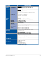
ASUS RS520A-E12 Series 1-5
(continued on the next page)
Model Name RS520A-E12-RS24U
Storage SAS Controller
Optional kits:
ASUS PIKE II 3008 8-port SAS 12Gb/s HBA card
Broadcom MegaRAID 9560-16i
Storage
Bays
Storage Bay
Front bays:
24 x 2.5” hot-swap drive bays
- 24 x NVMe or
- 16 x NVMe + 8x SAS/SATA (from HBA/RAID card) or
- 12 x NVMe + 12x SAS/SATA
- 8 x NVMe + 16x SAS/SATA
Rear bays:
2 x 2.5-inch Storage Device Trays (SATA III)
* SAS support only from optional SAS HBA/RAID card
Backplane
connectors
12 x MCIO x2 (for NVMe)
6 x SlimSAS x4 (for SATA)
MB on-board
connectors
2 x M.2 connectors
8 x MCIO connectors
Default Cable Optional, in CPQ under the option “others”
NVMe upgrade
option
Support 24 x NVMe: 12 x NVMe cable
Support 16 x NVMe: 8 x NVMe cable
Support 12 x NVMe: 6 x NVMe cable
Networking
1 x Dual Port Intel I350-AM2 Gigabit LAN controller
1 x Management Port
Optional OCP Adapter:
Up to 100Gb/s Ethernet / InfiniBand Adapter
VGA BMC Integrated (Aspeed AST2600 256MB)
Graphic
4 x Single-wide GPU (FHFL) or
2 x Double-wide GPU (FHFL)
(Not supported in 24 x NVMe model)
Front I/O Ports 2 x USB 3.2 Gen 1 ports
1 x Power button
Rear I/O Ports
2 x USB 3.2 Gen 1 ports
1 x VGA port
1 x RJ-45 Mgmt LAN port
2 x RJ-45 1GbE LAN ports

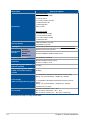
Chapter 1: Product Introduction
1-6
*Specifications are subject to change without notice.
Model Name RS520A-E12-RS24U
Switch/LED
Front Switch/LED:
1 x Power Switch (w/LED)
1 x Reset Switch
1 x Location Switch (w/LED)
1 x HDD Access LED
1 x Message LED
LAN 1-2 LED
Rear Switch/LED:
1 x Port80 LED (Q-Code)
1 x Power Switch w/LED
1 x Location Switch w/LED
1 x Message LED
Security Options TPM-SPI Module (optional)
PFR Module (optional)
OS Support Please find the latest OS support from https://www.asus.com/.
Management
Solution
Software ASUS Control Center (Classic)
Out of Band
Remote
Management
On-Board ASMB11-iKVM for KVM-over-IP
Regulatory Compliance CE, RCM, FCC (Class A)
Dimension 840mm x 449mm x 88.1mm (2U)
33.07in x 17.68in x 3.47in
Net Weight Kg (CPU, DRAM &
HDD not included) 19.14Kg
Gross Weight Kg (CPU, DRAM
& HDD not included, Packing
include)
26.63Kg
Power Supply
(different configuration by region)
1+1 Redundant 1200W 80 PLUS Platinum Power Supply
Rating: 100-127/200-240Vac, 10A/8A (x2), 50/60Hz
1+1 Redundant 1600W 80 PLUS Platinum/Titanium Power
Supply
Rating: 100-127/200-240Vac, 12A/9.5A (x2), 50/60Hz
(240Vdc Only for China)
Environment
Operation temperature: 10°C ~ 35°C
Non operation temperature: -40°C ~ 60°C
Non operation humidity: 20% ~ 90% (Non condensing)

ASUS RS520A-E12 Series 1-7
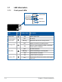
1.4 Front panel features
The barebone server displays a simple yet stylish front panel with easily accessible features.
The power and reset buttons, LED indicators are located on the front panel.
Refer to section 1.7 LED information for the LED descriptions.
• Bay 1 to bay 24 supports NVMe for 24 NVMe configuration.
• Bay 5 to bay 20 supports NVMe; others support SATA/SAS* from HBA/RAID for 16
NVMe configuration.
• Bay 5 to bay 16 supports NVMe, others supports SATA/SAS* for 12 NVMe
configuration.
* SAS support only from HBA/RAID card.
24 x 2.5” Storage Bays
1 2
3 4
RESET
USB 3.2 Gen 1 ports Front panel LEDs & buttons
Handle
Handle
Bay 1 Bay 24
1 2
3 4
RESET
Front bezel
Bezel keylock
Bezel release latch
For extra security, a front bezel (purchased separately) can be installed to prevent
unauthorized physical access to the hard drives and power button.

Chapter 1: Product Introduction
1-8
• * This port is for ASUS ASMB11-iKVM only.
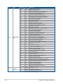
• The Q-Code LED provides the most probable cause of an error code as a starting
point for troubleshooting. The actual cause may vary from case to case.
• Refer to the Q-Code table for details.
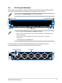
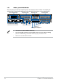
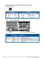
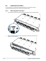
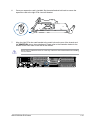
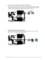
1.5 Rear panel features
The rear panel includes the expansion slots, and system power sockets. The middle part
includes the I/O shield with openings for the rear panel connectors on the motherboard.
2 x 2.5” Storage Bays
VGA port
Lan port 1
Lan port 2
Location button
Power button
Management LAN port 1*
USB 3.2 Gen 1 ports
Redundant Power supply
and Power cord connector OCP 3.0 slot
Expansion slotsExpansion slots
Q-Code LED
Expansion slot

ASUS RS520A-E12 Series 1-9
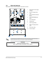
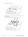
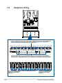
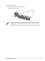
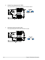
1.6 Internal features
The barebone server includes the basic components as shown.
WARNING
HAZARDOUS MOVING PARTS
KEEP FINGERS AND OTHER BODY PARTS AWAY
A protection film is pre-attached to the front cover before shipping. Please remove the
protection film before turning on the system for proper heat dissipation.
1. Redundant Power supply
(hidden)
2. 2 x 2.5“ storage device
trays
3. ASUS K14PA-U24 Server
Board
4. SATA/SAS/NVMe back
panel
5. Front USB panel
6. System fans
7. Asset Tag (hidden)
8. 24 x 2.5“ storage device
trays
9. PCIe riser cards
10. Front I/O panel

Chapter 1: Product Introduction
1-10
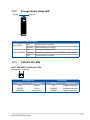
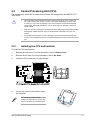
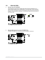
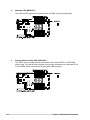
1.7 LED information
1.7.1 Front panel LEDs
LED Icon Display status Description
Power LED ON System power ON
Storage device
access LED
OFF No activity
Blinking Read/write data into the storage device
Message LED
OFF System is normal; no incoming event
ON With the onboard ASMB10-iKVM: a hardware
monitor event is indicated
LAN LEDs
OFF No LAN connection
Blinking LAN is transmitting or receiving data
ON LAN connection is present
Location LED
ON Location switch is pressed
OFF Normal status (Press the location switch again
to turn off)
1 2
3 4
RESET
1 2
3 4
RESET
Message LED
Storage device
access LED
Location button
Power button
LAN LEDs
RESET button
La pagina si sta caricando...
La pagina si sta caricando...
La pagina si sta caricando...
La pagina si sta caricando...
La pagina si sta caricando...
La pagina si sta caricando...
La pagina si sta caricando...
La pagina si sta caricando...
La pagina si sta caricando...
La pagina si sta caricando...
La pagina si sta caricando...
La pagina si sta caricando...
La pagina si sta caricando...
La pagina si sta caricando...
La pagina si sta caricando...
La pagina si sta caricando...
La pagina si sta caricando...
La pagina si sta caricando...
La pagina si sta caricando...
La pagina si sta caricando...
La pagina si sta caricando...
La pagina si sta caricando...
La pagina si sta caricando...
La pagina si sta caricando...
La pagina si sta caricando...
La pagina si sta caricando...
La pagina si sta caricando...
La pagina si sta caricando...
La pagina si sta caricando...
La pagina si sta caricando...
La pagina si sta caricando...
La pagina si sta caricando...
La pagina si sta caricando...
La pagina si sta caricando...
La pagina si sta caricando...
La pagina si sta caricando...
La pagina si sta caricando...
La pagina si sta caricando...
La pagina si sta caricando...
La pagina si sta caricando...
La pagina si sta caricando...
La pagina si sta caricando...
La pagina si sta caricando...
La pagina si sta caricando...
La pagina si sta caricando...
La pagina si sta caricando...
La pagina si sta caricando...
La pagina si sta caricando...
La pagina si sta caricando...
La pagina si sta caricando...
La pagina si sta caricando...
La pagina si sta caricando...
La pagina si sta caricando...
La pagina si sta caricando...
La pagina si sta caricando...
La pagina si sta caricando...
La pagina si sta caricando...
La pagina si sta caricando...
La pagina si sta caricando...
La pagina si sta caricando...
La pagina si sta caricando...
La pagina si sta caricando...
La pagina si sta caricando...
La pagina si sta caricando...
La pagina si sta caricando...
La pagina si sta caricando...
La pagina si sta caricando...
La pagina si sta caricando...
La pagina si sta caricando...
La pagina si sta caricando...
La pagina si sta caricando...
La pagina si sta caricando...
La pagina si sta caricando...
La pagina si sta caricando...
La pagina si sta caricando...
La pagina si sta caricando...
La pagina si sta caricando...
La pagina si sta caricando...
La pagina si sta caricando...
La pagina si sta caricando...
La pagina si sta caricando...
La pagina si sta caricando...
La pagina si sta caricando...
La pagina si sta caricando...
La pagina si sta caricando...
La pagina si sta caricando...
La pagina si sta caricando...
La pagina si sta caricando...
La pagina si sta caricando...
La pagina si sta caricando...
La pagina si sta caricando...
La pagina si sta caricando...
La pagina si sta caricando...
La pagina si sta caricando...
La pagina si sta caricando...
La pagina si sta caricando...
La pagina si sta caricando...
La pagina si sta caricando...
La pagina si sta caricando...
La pagina si sta caricando...
La pagina si sta caricando...
La pagina si sta caricando...
La pagina si sta caricando...
La pagina si sta caricando...
La pagina si sta caricando...
La pagina si sta caricando...
La pagina si sta caricando...
La pagina si sta caricando...
La pagina si sta caricando...
La pagina si sta caricando...
La pagina si sta caricando...
La pagina si sta caricando...
La pagina si sta caricando...
La pagina si sta caricando...
La pagina si sta caricando...
La pagina si sta caricando...
La pagina si sta caricando...
La pagina si sta caricando...
La pagina si sta caricando...
La pagina si sta caricando...
La pagina si sta caricando...
La pagina si sta caricando...
La pagina si sta caricando...
La pagina si sta caricando...
La pagina si sta caricando...
La pagina si sta caricando...
La pagina si sta caricando...
La pagina si sta caricando...
La pagina si sta caricando...
La pagina si sta caricando...
La pagina si sta caricando...
La pagina si sta caricando...
La pagina si sta caricando...
La pagina si sta caricando...
La pagina si sta caricando...
La pagina si sta caricando...
La pagina si sta caricando...
La pagina si sta caricando...
La pagina si sta caricando...
La pagina si sta caricando...
-
 1
1
-
 2
2
-
 3
3
-
 4
4
-
 5
5
-
 6
6
-
 7
7
-
 8
8
-
 9
9
-
 10
10
-
 11
11
-
 12
12
-
 13
13
-
 14
14
-
 15
15
-
 16
16
-
 17
17
-
 18
18
-
 19
19
-
 20
20
-
 21
21
-
 22
22
-
 23
23
-
 24
24
-
 25
25
-
 26
26
-
 27
27
-
 28
28
-
 29
29
-
 30
30
-
 31
31
-
 32
32
-
 33
33
-
 34
34
-
 35
35
-
 36
36
-
 37
37
-
 38
38
-
 39
39
-
 40
40
-
 41
41
-
 42
42
-
 43
43
-
 44
44
-
 45
45
-
 46
46
-
 47
47
-
 48
48
-
 49
49
-
 50
50
-
 51
51
-
 52
52
-
 53
53
-
 54
54
-
 55
55
-
 56
56
-
 57
57
-
 58
58
-
 59
59
-
 60
60
-
 61
61
-
 62
62
-
 63
63
-
 64
64
-
 65
65
-
 66
66
-
 67
67
-
 68
68
-
 69
69
-
 70
70
-
 71
71
-
 72
72
-
 73
73
-
 74
74
-
 75
75
-
 76
76
-
 77
77
-
 78
78
-
 79
79
-
 80
80
-
 81
81
-
 82
82
-
 83
83
-
 84
84
-
 85
85
-
 86
86
-
 87
87
-
 88
88
-
 89
89
-
 90
90
-
 91
91
-
 92
92
-
 93
93
-
 94
94
-
 95
95
-
 96
96
-
 97
97
-
 98
98
-
 99
99
-
 100
100
-
 101
101
-
 102
102
-
 103
103
-
 104
104
-
 105
105
-
 106
106
-
 107
107
-
 108
108
-
 109
109
-
 110
110
-
 111
111
-
 112
112
-
 113
113
-
 114
114
-
 115
115
-
 116
116
-
 117
117
-
 118
118
-
 119
119
-
 120
120
-
 121
121
-
 122
122
-
 123
123
-
 124
124
-
 125
125
-
 126
126
-
 127
127
-
 128
128
-
 129
129
-
 130
130
-
 131
131
-
 132
132
-
 133
133
-
 134
134
-
 135
135
-
 136
136
-
 137
137
-
 138
138
-
 139
139
-
 140
140
-
 141
141
-
 142
142
-
 143
143
-
 144
144
-
 145
145
-
 146
146
-
 147
147
-
 148
148
-
 149
149
-
 150
150
-
 151
151
-
 152
152
-
 153
153
-
 154
154
-
 155
155
-
 156
156
-
 157
157
-
 158
158
-
 159
159
-
 160
160


Asus RS520A-E12-RS24U Manuale utente
- Categoria
- Schede madri
- Tipo
- Manuale utente
in altre lingue
- English: Asus RS520A-E12-RS24U User manual