Marmitek IR Control 10 XTRA IR Extender Manuale utente
- Categoria
- Estensori AV
- Tipo
- Manuale utente


© MARMITEK
2

IR Control 10 XTRA™
3
ENGLISH
1 Table of contents
1 Table of contents ................................................................................................... 3
2 Safety instructions .................................................................................................. 4
3 Your product .......................................................................................................... 5
3.1 Introduction ............................................................................................................ 5
3.2 Contents of the package ........................................................................................ 5
4 Getting started ....................................................................................................... 5
4.1 How it works .......................................................................................................... 5
4.2 Connections ........................................................................................................... 6
4.2.1 IR Input ................................................................................................... 6
4.2.2 POWER Input ......................................................................................... 6
4.2.3 IR Output ................................................................................................ 6
4.3 Installation .............................................................................................................. 6
4.3.1 Locating the IR Receiver ......................................................................... 6
4.3.2 Placing the IR extension cable with one blaster LED ............................... 7
5.3 Installation of the IR extension cable with emitter LEDs (as problem solution) .. 7
4.3.3 Locating the IR Module ........................................................................... 7
4.3.4 Connecting the IR Module ....................................................................... 7
4.3.5 Perform a function test of the product ...................................................... 8
4.4 Advanced installation ............................................................................................. 8
4.4.1 Connecting multiple IR receivers ............................................................. 8
4.4.2 Extend the cable length of the IR receiver ............................................... 8
4.4.3 Connecting AVR connection cable .......................................................... 8
5 Frequently asked questions ................................................................................... 9
6 Technical specifications ....................................................................................... 10
7. Optional ............................................................................................................... 11
8 Notification ........................................................................................................... 11
8.1 Declaration of Conformity ..................................................................................... 11
8.2 Recycling ............................................................................................................. 12
8.3 Copyrights ............................................................................................................ 12

© MARMITEK
4
2 Safety instructions
Please read these instructions thoroughly before you use the device and keep
them for future reference.
• Only for indoor use.
• Do not use the product in a damp environment or near water.
• Do not expose the product to extremely high or low temperatures, strong light
sources or direct sunlight.
• This product is not a toy. Keep out of reach of children.
• Connect the adapter to the mains only after you have verified that the line voltage
corresponds to the value specified on the type plates.
• Never connect a power adapter if it's damaged. In such cases, please contact
your supplier.
• Disconnect the AC/DC power adapter from the mains when this device is not in
use for prolonged time.
• Never open the product: the device may contain parts with deadly voltage.
• Repairs or service should only be performed by qualified personnel.
• Improper use, self-installed modifications or repairs will void any and all
warranties.
• Marmitek does not accept any product responsibility for incorrect use of the
product or use other than for which the product is intended.
• Marmitek does not accept liability for any consequential damage other than the
legal product responsibility.

IR Control 10 XTRA™
5
ENGLISH
3 Your product
3.1 Introduction
Congratulations on your purchase of the IR Control 10 XTRA™. With it you can extend
the IR (infrared) signals of remote controls. The IR Control 10 XTRA™ makes it
possible to operate A/V devices while these are in a closed cupboard or when your A/V
equipment is out of sight.
3.2 Contents of the package
1 x IR Module
1 x IR Receiver
2 x IR Extension cable with one IR blaster LED
1 x IR Extension cable with two IR emitter LEDs
1 x AVR connection cable
1 x Power adaptor
1 x Manual
4 Getting started
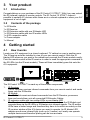
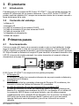
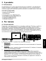
4.1 How it works
Locate your A/V equipment in a closed cupboard, TV cabinet or even in another room.
The IR receiver must be installed in view of your own remote control. Stick the IR
blaster LED wherever you want in the cabinet and conceals the IR main module neatly.
Point the remote control at the IR receiver in order to send the appropriate command to
the IR LEDs (via the IR main module). These will then immediately pass this onto the
A/V equipment.
The IR Control 10 XTRA™ is made up of three main components;
1. IR Receiver
The IR Receiver receives infrared commands from your remote control and sends
these onto the IR Module.
2. IR Module
The IR Module receives infrared commands from the IR Receiver, processes
them and sends them onto all connected IR Extender Cables.
3. IR extension cable with two emitter LEDs or one blaster LED
The IR extension cable receives the infrared commands from the IR Module and
converts them via the IR LEDs or IR blasters into infrared signals. The IR emitter
LEDs have a limited range and therefore they have to be stuck accurately on the
IR receiver window of the A/V device you want to operate. An IR blaster LED
radiates much more infrared light (even up to 2 meters) so it easily can operate
multiple devices and therefore placing can be less accurate.

© MARMITEK
6
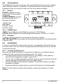
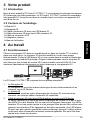
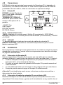
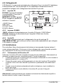
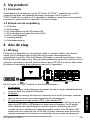
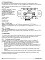
4.2 Connections
The IR Module is the main component that connects IR Receivers, the power adapter
and IR Extender Cables to one another. All of the IR Module connections are now
explained so that you can get the most out of all of the options available.
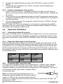
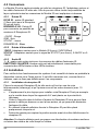
4.2.1 IR Input
IR RCVR: standard IR input
(3.5mm jack) for the enclosed
IR Receiver
SCREW TERMINAL: IR input
for connecting up to 6 IR
Receivers in parallel.
+12VDC: Red
GND: Black
STATUS: Yellow
IR DATA: White
4.2.2 POWER Input
12VDC: Power adapter for the IR Module (enclosed), 5VDC/200mA
STATUS: Power adapter for the status signal (not enclosed), 5-24VDC or 5-12VAC
4.2.3 IR Output
1 – 4: four mini jack outputs for connecting the IR extension cables.
EMITTER / BLASTER: every output can be switched separately for connecting blaster
or emitter LEDs.
4.3 Installation
In order to check that the system works correctly, it is advisable to first test the set-up
you had in mind. To do so, connect everything as described below but do not stick the
components securely.
4.3.1 Locating the IR Receiver
Place the very small IR Receiver in a way that it is visible for your (infrared) remote
control and it can receive the sent commands (max. 10 meters).
The most logical location for the IR receiver is, for example, on the cabinet in
which the A/V equipment is located or near the TV.
You can run the cable underneath or behind, using the notch at the back of the IR
receiver housing; this allows the cable to be hidden easily.
Use the self-adhesive strip which is supplied to locate the IR receiver just about
anywhere you please.
Experiment with the location before you stick the IR receiver in its final position.
Note! The sticky strip may lead to discolouration or leave glue residues on certain
surfaces.
EMITTER
BLASTER
IR O UT PUT
IR I NPUT POWER INPUT
STAT U S
+12VD C
GND
IR DATA
IR RCVR
STATU
12VD C
1
2
3 4
1
2
3 4
5-24VD C

IR Control 10 XTRA™
7
ENGLISH
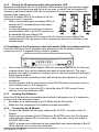
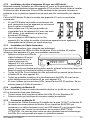
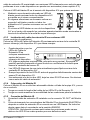
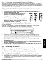
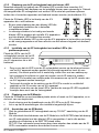
4.3.2 Placing the IR extension cable with one blaster LED
Marmitek recommends the use of IR blaster LEDs because they can operate multiple
A/V devices at the same time and they are very easy to install. Use the supplied IR
extension cable with emitter LEDs only as solution if one or more devices cannot be
operated (see chapter 5.3).
Place the IR blaster LED in the cabinet of the A/V
devices you want to operate.
With a correct placement one blaster LED can
operate all A/V devices placed in the same
compartment.
In some situations it is necessary to place a
second blaster LED if not all A/V devices can
be operated with one blaster LED.
Or you place the blaster LED on one of the A/V devices in the middle of the
cabinet and the other equipment will be operated as well by the reflection of the
infrared signal.
5.3 Installation of the IR extension cable with emitter LEDs (as problem solution)
Place the LEDs from the IR extender cable precisely on the IR window (infrared
sensor) on the A/V equipment that you wish to operate.
Ensure that the IR extender cable’s LEDs are stuck precisely on the A/V device’s
infrared sensor (this can be extremely accurate on some devices). The exact
position can easily be located by shining a torch on the front panel and looking for
the IR sensor window.
All IR LEDs include self-adhesive film with which they are attached to your A/V
equipment.
Test the position and the performance of the IR LEDs before you secure them to
the IR window on your A/V equipment.
If you use only one of the two LED’s, leave the other IR LED unused. Never
remove it from the extension cable!
4.3.3 Locating the IR Module
Mount the IR Module at an accessible place behind or alongside your A/V equipment,
in the vicinity of an electrical socket.
Be aware of the cable length of the IR LEDs and the IR receiver.
Make sure the connections for installation remain accessible.
4.3.4 Connecting the IR Module
1. Connect the installed IR extension cables to the ‘IR OUT’ connector of the IR
Module.
2. Switch only the switches of the IR Module in BLASTER mode if an IR extension
cable with one blaster LED is connected. In any other case, leave the switch in
the EMITTER mode.
NOTE: a wrong choice between the two possibilities can cause damage to the IR
LEDs and they can even become defective.

© MARMITEK
8
3. Connect the installed IR receiver cable to the ‘IR RCVR’ connector of the IR
Module.
4. Connect the power adapter to the ‘12VDC’ connector of the IR Module and
connect it to the mains.
4.3.5 Perform a function test of the product
1. If the IR Control 10 XTRA™ is properly connected, the light on the IR receiver
flashes if you push a button on the (infrared) remote control and aim it towards the
IR receiver.
2. Close the doors of your cabinet and make sure the A/V equipment cannot receive
an infrared command directly from the remote control. Otherwise this could lead to
operating problems.
3. You can now operate your A/V equipment via the IR Control 10 XTRA™ through
the closed cabinet doors!
If the IR Control 10 XTRA is not reacting in a correct way, try experimenting with the
placement of the IR receiver and/or IR extension cables (emitter or blaster). Placing it
somewhere else could give a better result.
4.4 Advanced installation
4.4.1 Connecting multiple IR receivers
If you want to operate your A/V equipment from multiple rooms, you can connect up to
6 IR receivers in parallel to the IR module. Cut therefore the standard connector of the
IR receiver and connect it to the SCREW TERMINAL of the IR module (see paragraph
4.1).
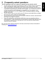
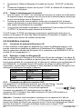
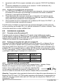
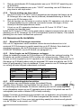
4.4.2 Extend the cable length of the IR receiver
Only the cables between the IR receiver and the IR module can be extended. The IR
cables with emitter or blaster LEDs cannot be extended. Place the IR module as close
as possible to your A/V equipment and extend the cable between the IR receiver and
the IR module if needed to a maximum of 300 meters with CAT5 cable (or equal). Cut
the standard 3.5mm connector off the IR receiver cable and extend the cable according
to the example below.
IR receiver
CAT5 cable
IR module
Red
Orange
+12VDC
Black
Blue
GND
Yellow
Green
STATUS
White
Brown
IR DATA
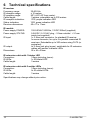
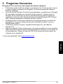
4.4.3 Connecting AVR connection cable
A/V equipment from different brands (for instance Denon, Yamaha, Onkyo, Marantz,
etc) have a direct “IR IN” connector at the back. A direct connection with the AVR
connection cables is an alternative way of connecting your A/V equipment. The use of
an IR extension cable (with emitter or blaster LED) is
not necessary here.
Note; check the technical documentation of your
equipment to decide whether the IR module of the IR
control 10 XTRA can be connected directly. Most IR
cables use a 3.5mm mono jack connector where the tip is used for the “IR Data” and
the sleeve for “GND”.

IR Control 10 XTRA™
9
ENGLISH
5 Frequently asked questions
The A/V equipment does not respond to signals from my remote control.
The IR receiver has a receiving sensitivity of about 10 metres with an acceptance
angle of 90 degrees. Range is also dependent on the remote control used.
If the ‘IR data’ light on the IR Receiver is continuously illuminated, the IR receiver
is probably being disrupted by another infrared signal. Try to locate the IR receiver
so that it encounters as little disruption as possible from, for example, direct
sunlight, Flat Screen TVs, (LCD, Plasma, LED), fluorescent lighting or energy-
efficient light bulbs.
The IR receiver does not work with some A/V devices and models that use higher
IR frequencies such as Bang & Olufsen (B&O).
Ensure that the IR receiver and the IR extender cable are correctly connected and
that these are plugged in properly.
Some IR windows from set-top and satellite boxes are very sensitive and are
easily disrupted. These devices then receive too much infrared light and will either
work badly or not work at all. Relocate the IR LED so that less infrared light is
received via the IR window.
Do you have other questions that have not been resolved by the above information?
Please go to www.marmitek.com

© MARMITEK
10
6 Technical specifications
IR receiver
Frequency range: 30-60 KHz
IR reception range: ± 10 meters
IR reception angle: 90º (+45º/-45º from centre)
Cable length: 3 meters, extendable up to 300 meters
IR reception indication: YES, purple indication LED
Status indication: YES, green indication LED
Receiver dimensions: 40 x 13 x 11mm
IR module
Power supply POWER: 100-240VAC 50/60Hz, 12VDC 200mA (supplied)
Power supply STATUS: 5-24VDC / 5-12VAC plug, - 5.5mm outside / + 2.1mm
inside (not supplied)
IR input: 1x 3.5mm jack connector, for standard IR receiver
1x screw connector, for up to 6 in parallel connected IR
receivers. Extendable up to 300 meters using CAT5 (or
equivalent)
IR output: 4x 3.5mm jack plug (mono), switchable for IR extension
cables with emitter or blaster LEDs
Dimensions: 95 x 46 x 20mm
IR extension cable with 1 blaster LED
Connection: 3.5mm jack plug (mono)
IR LEDs: 1x IR blaster LED
Cable length: 3 meters
IR extension cable with 2 emitter LEDs
Connection: 3.5mm jack plug (mono)
IR LEDs: 2x IR emitter LEDs
Cable length: 3 meters
Specifications may change without prior notice.

IR Control 10 XTRA™
11
ENGLISH
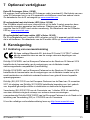
7. Optional
Extra IR receiver (Art. nr. 08142)
Every system needs at least one IR receiver (up to 6). With an extra IR receiver you
can also operate your A/V devices from another room. See datasheets of the IR
receivers at www.marmitek.com
IR extension cable with one blaster LED (Art. nr. 08144)
An IR blaster radiates much more infrared light (even up to 2 meters) so it can operate
multiple devices. Placement of the IR blaster is a lot less critical as opposed to IR
LEDs. See datasheets of the IR Blaster LED on www.marmitek.com.
IR extension cable with two emitter LEDs (Art. nr. 08145)
The LEDs of the IR extension cables with 2 emitter LEDs have to be stuck to the A/V
device(s) you want to operate. See datasheets of the IR emitter LEDs on
www.marmitek.com.
8 Notification
8.1 Declaration of Conformity
Hereby, Marmitek BV declares that this IR Control 10 XTRA™ is in compliance
with the essential requirements and other relevant provisions of the following
Directives:
Directive 2014/30/EU of the European Parliament and of the Council of 26 February
2014 on the harmonisation of the laws of the Member States relating to
electromagnetic compatibility (recast)
Directive 2014/35/EU of the European Parliament and of the Council of 26 February
2014 on the harmonisation of the laws of the Member States relating to the making
available on the market of electrical equipment designed for use within certain voltage
limits.
Directive (EU) 2017/2102 of the European Parliament and of the Council of 15
November 2017 amending Directive 2011/65/EU on the restriction of the use of certain
hazardous substances in electrical and electronic equipment.
Commission Regulation (EU) 2019/1782 of 1 October 2019 laying down Ecodesign
requirements for external power supplies pursuant to Directive 2009/125/EC of the
European Parliament and of the Council and repealing Commission Regulation (EC)
No 278/2009.
You can read the full Declaration of Conformity at http://www.marmitek.com

© MARMITEK
12
8.2 Recycling
Environmental Information for Customers in the European Union and other
European countries with separate collection systems.
This symbol on the product or on its packaging indicates that this product shall not
be treated as household waste. Instead it shall be handed over to the applicable
collection point for the recycling of electrical and electronic equipment. It is your
responsibility to dispose of this and other electric and electronic equipment via
designated collection facilities appointed by the government or local authorities.
Correct disposal and recycling will help prevent potential negative consequences to the
environment and human health. For more detailed information about the disposal of
your old equipment, please contact your local authorities, waste disposal service, or
the shop where you purchased the product.
8.3 Copyrights
Marmitek is a trademark of Vogel’s Holding B.V. Every effort has been made to ensure
that the information in this manual is accurate. Marmitek is not responsible for printing
or clerical errors. Copyright and all other proprietary rights in the content (including but
not limited to model numbers, software, audio, video, text and photographs) rests with
Marmitek B.V. Any use of the Content, but without limitation, distribution, reproduction,
modification, display or transmission without the prior written consent of Marmitek is
strictly prohibited. All copyright and other proprietary notices shall be retained on all
reproductions. Other company and product names mentioned herein may be
trademarks of their respective companies. Mention of third-party products is for
informational purposes only and constitutes neither an endorsement nor a
recommendation. Marmitek assumes no responsibility with regard to the performance
or use of these products.
Marmitek BV - PO Box 4257 - 5604 EG Eindhoven

IR Control 10 XTRA™
13
DEUTSCH
1 Inhaltsverzeichnis
1 Inhaltsverzeichnis ................................................................................................ 13
2 Sicherheitshinweise ............................................................................................. 14
3 Ihr Produkt ........................................................................................................... 15
3.1 Einführung ........................................................................................................... 15
3.2 Verpackungsinhalt ............................................................................................... 15
4 Los geht’s ............................................................................................................ 15
4.1 Arbeitsweise ........................................................................................................ 15
4.2 Anschlüsse .......................................................................................................... 16
4.2.1 IR Input ................................................................................................. 16
4.2.2 POWER Input ....................................................................................... 16
4.2.3 IR Output .............................................................................................. 16
4.3 Installation ............................................................................................................ 16
4.3.1 Aufstellung des ir empfängers ............................................................... 16
4.3.2 Anbringung des IR Verlängerungskabels mit einem Blaster LED ........... 17
4.3.3 Installation des IR Verlängerungskabels ................................................ 17
4.3.4 Installation des IR moduls ..................................................................... 17
4.3.5 Anschluss des IR Moduls ...................................................................... 17
4.3.6 Betriebstest des Produkts ..................................................................... 18
4.4 Verfeinerte Installation ......................................................................................... 18
4.4.1 Mehrere IR Empfänger anschließen ...................................................... 18
4.4.2 Kabellänge des IR Empfängers verlängern ........................................... 18
4.4.3 AVR Verbindungskabel anschließen ..................................................... 18
5 Häufig gestellte Fragen (FAQs) ............................................................................ 19
6 Technische daten ................................................................................................. 20
1. Zusätzlich erhältlich .............................................................................................. 21
7 Hinweis ................................................................................................................ 21
7.1 Konformitätserklärung .......................................................................................... 21
7.2 Recycling ............................................................................................................. 22
7.3 Urheberrechte ...................................................................................................... 22

© MARMITEK
14
2 Sicherheitshinweise
Lesen Sie diese Gebrauchsanleitung sorgfältig durch, bevor Sie das Gerät in
Betrieb nehmen und bewahren Sie diese Anleitung bitte für eventuelle, spätere
Bedarfsfälle auf.
• Ausschließlich für Verwendung in Innenräumen.
• Dieses Produkt nicht in einer feuchten Umgebung oder nahe Wasserquellen
verwenden.
• Setzen Sie dieses Produkt nicht extrem hohen oder niedrigen Temperaturen,
starken Lichtquellen und direkter Sonneneinstrahlung aus.
• Dieses Produkt ist kein Spielzeug. Außer Reichweite von Kindern halten.
• Schließen Sie den Netzadapter erst dann an das Stromnetz an, nachdem Sie
überprüft haben, ob die Netzspannung mit dem auf dem Typenschild angegeben
Wert übereinstimmt.
• Schließen Sie niemals einen Netzadapter an, wenn diese beschädigt sind. In
diesem Fall nehmen Sie Kontakt mit Ihrem Lieferanten auf.
• Entfernen Sie den AC/DC Speisungsadapter aus der Steckdose, wenn Sie das
Gerät längere Zeit nicht nutzen.
• Das Produkt niemals öffnen: Das Gerät kann Teile enthalten, worauf
lebensgefährliche Stromspannung steht.
• Überlassen Sie Reparaturen oder Wartung nur Fachleuten.
• Bei einer zweckwidrigen Verwendung, selbst angebrachten Veränderungen oder
selbst ausgeführten Reparaturen verfallen alle Garantiebestimmungen.
• Marmitek übernimmt bei einer falschen Verwendung des Produkts oder bei einer
anderen Verwendung des Produktes als für den vorgesehenen Zweck keinerlei
Produkthaftung.
• Marmitek übernimmt für Folgeschäden keine andere Haftung als die gesetzliche
Produkthaftung.

IR Control 10 XTRA™
15
DEUTSCH
3 Ihr Produkt
3.1 Einführung
Herzlichen Glückwunsch zum Erwerb des IR Control 10 XTRA™. Mit diesem Set
können Sie IR (Infrarot-) Signale von Fernbedienungen verlängern. Das IR Control 10
XTRA™ ermöglicht es A/V Geräte zu bedienen, während diese sich in einem
geschlossenen Schrank oder außer Sichtweite befinden.
3.2 Verpackungsinhalt
1x IR Modul
1x IR Empfänger
1x AVR Verbindungskabel
2x IR Verlängerungskabel mit einem IR Blaster LED
1x IR Verlängerungskabel mit zwei IR Emitter LED’s
1x Netzteil
1x Gebrauchsanleitung
4 Los geht’s
4.1 Arbeitsweise
Stellen Sie Ihre A/V Geräte in einen geschlossenen Schrank, Fernsehschrank oder in
einen anderen Raum. Der IR Empfänger muss in Sichtweite Ihrer eigenen
Fernbedienung installiert werden. Kleben Sie die IR Blaster LED an einen
gewünschten Ort im Schrank und verblenden Sie das IR Hauptmodul. Richten Sie die
Fernbedienung auf den IR Empfänger, um den gewünschten Befehl (über das IR
Hauptmodul) zu den IR LED’s zu versenden; wonach diese diesen Infrarot-Befehl
direkt an Ihre A/V Geräte weiterleiten.
Das IR Control 10 XTRA™ besteht aus drei Hauptbestandteilen;
1. IR Empfänger
Der IR Empfänger fängt Infrarot-Befehle Ihrer eigenen Fernbedienung auf und
sendet diese an das IR Modul weiter.
2. IR Modul
Das IR Modul empfängt die Infrarot-Befehle vom IR Empfänger, verarbeitet diese
und gibt sie an alle angeschlossene IR-Verlängerungskabel weiter.
3. IR Verlängerungskabel mit zwei Emitter LED’s oder einem Blaster LED
Das IR Verlängerungskabel empfängt die Infrarot-Befehle vom IR Modul und
wandelt sie über die IR LED’s oder IR Blaster in Infrarotsignale um. Die IR Emitter
LED's haben eine begrenzte Reichweite um müssen deshalb präzise auf das IR
Fenster des zu bedienenden A/V Gerätes geklebt werden. Ein IR Blaster strahlt
viel mehr Infrarotlicht ab (sogar bis über 2 Meter) wodurch dieser leichter mehrere
Geräte bedienen kann und Anbringung ungenauer sein darf.

© MARMITEK
16
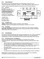
4.2 Anschlüsse
Das IR Modul ist der Hauptbestandteil der IR Empfänger, Netzteil und IR
Verlängerungskabel miteinander verbindet. Um alle Möglichkeiten optimal nutzen zu
können, werden nachstehend sämtliche Anschlüsse des IR Moduls erläutert.
4.2.1 IR Input
IR RCVR: Regulärer IR
Eingang (3.5mm Buchse) für
enthaltenen IR Empfänger
SCHRAUBTERMINAL: IR
Eingang, woran parallel
maximal 6 IR Empfänger
anschlossen werden können
+12VDC: Rot
GND: Schwarz
STATUS: Gelb
IR DATEN: Weiß
4.2.2 POWER Input
12VDC: Netzteil für das IR Modul (enthalten) 5VDC/200mA
STATUS: Netzteil für Statussignal (nicht enthalten) 5-24VDC of 5-12VAC
4.2.3 IR Output
1 – 4: Vier Mini Buchsenanschlüsse für den Anschluss der IR Verlängerungskabel
EMITTER / BLASTER: Jeder Ausgang kann einzeln geschaltet werden, um Blaster
oder Emitter LED’s anzuschließen.
4.3 Installation
Zur Kontrolle der Betriebsfähigkeit des Systems empfehlen wir, die von Ihnen geplante
Aufstellung zunächst auszuprobieren. Schließen Sie dazu alles wie nachstehend
beschrieben an, kleben oder schrauben Sie die Komponenten jedoch noch nicht fest.
4.3.1 Aufstellung des ir empfängers
Stellen Sie den äußerst kleinen IR Empfänger in Sichtseite Ihrer (Infrarot)
Fernbedienung auf, sodass dieser die übertragenen Befehle empfangen kann (max.
10 Meter).
Bester Standort für den IR Empfänger wäre beispielsweise auf dem Schrank, in
dem sich die A/V Geräte befinden oder in Nähe des Fernsehers.
Um das Kabel unsichtbar zu verlegen, können Sie es aufgrund der Aussparung
im Gehäuse an der Rückseite des IR Empfängers durch die Unter- oder
Rückseite führen.
Der anliegende, selbstklebende Streifen ermöglicht Anbringung an nahezu allen
Stellen.
Ermitteln Sie die richtige Stelle, bevor Sie den IR Empfänger definitiv festkleben.
Achtung! Der Klebestreifen kann auf bestimmten Oberflächen eine Verfärbung
verursachen oder nach Entfernung Klebereste hinterlassen.
EMITTER
BLASTER
IR O UT PUT
IR I NPUT POWER INPUT
STAT U S
+12VD C
GND
IR DATA
IR RCVR
STATU
12VD C
1
2
3 4
1
2
3 4
5-24VD C

IR Control 10 XTRA™
17
DEUTSCH
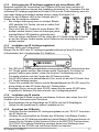
4.3.2 Anbringung des IR Verlängerungskabels mit einem Blaster LED
Marmitek empfiehlt die Verwendung von IR Blaster LEDs weil diese mehrere AV
Geräte zugleich bedienen können und Installation kinderleicht ist. Verwenden Sie das
enthaltene IR Verlängerungskabel mit Emitter LEDs nur als Problemlösung, wenn ein
oder mehr Geräte nicht bedient werden können (sehen Sie Kapitel 5.3).
Kleben Sie die IR Blaster LED in den Schrank des A/V
Geräts, das Sie bedienen möchten.
Bei richtiger Anbringung kann ein einziges Blaster
LED sämtliche A/V Geräte, die sich im selben Feld
befinden, bedienen.
Wenn nicht alle A/V Geräte mit einem Blaster LED
bedient werden können, kann die Anbringung einer
zweiten Blaster LED bisweilen notwendig sein.
Oder Sie bringen die Blaster LED an einem der A/V Geräte mittig des Schranks
an und die übrigen Geräte werden durch Reflexion des Infrarotsignals auch
bedient werden.
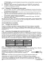
4.3.3 Installation des IR Verlängerungskabels
Mit Emitter LEDs (als Problemlöser)
Bringen Sie die LED’s des IR Verlängerungskabels akkurat auf dem IR Fenster
(Infrarotsensor) der zu bedienenden A/V Geräte an.
Die LED des IR Verlängerungskabels müssen präzise auf den Infrarotsensor des
A/V Geräts geklebt werden; das erfordert große Genauigkeit. Sie finden die
genaue Position ganz einfach, indem Sie mit einer Taschenlampe auf die
Frontseite scheinen und das Fenster des IR Sensors suchen.
Alle IR LEDs haben eine selbstklebende Folie, womit sie auf die IR Fenster Ihrer
A/V Geräte befestigt werden.
Testen Sie zunächst die Position und die Betriebsfähigkeit der IR LED, bevor Sie
diese definitiv an das IR Fenster Ihres A/V Geräts kleben.
Benötigen Sie nur eines der zwei IR LED, lassen Sie die zweite IR LED dann
ungebraucht. Entfernen Sie diese niemals vom Verlängerungskabel!
4.3.4 Installation des IR moduls
Installieren Sie das IR Modul an einen erreichbaren Ort hinter oder neben Ihren A/V
Geräten und in Reichweite einer Steckdose.
Berücksichtigen Sie die Kabellänge der IR LEDs und des IR Empfängers.
Halten Sie die Anschlüsse für weitere Installationen frei.
4.3.5 Anschluss des IR Moduls
1. Schließen Sie das installierte IR Verlängerungskabel an den “IR OUT“ Anschluss
des IR Moduls an.
2. Schalten Sie ausschließlich die Schalter des IR Moduls in die Blaster Position,
wenn daran ein IR Verlängerungskabel mit einem Blaster LED angeschlossen ist.
Lassen Sie die Schalter in allen anderen Fällen in der EMITTER Position stehen.
ACHTUNG: Eine falsche Einstellung zwischen diesen zwei Stellungen kann
Schäden an den IR LEDs und somit einen Defekt verursachen.

© MARMITEK
18
3. Schließen Sie das installierte IR Empfängerkabel an den “IR RCVR“ Anschluss
des IR Moduls an.
4. Schließen Sie den Netzteil an den "12VDC" Anschluss des IR Moduls an und
stecken Sie den Adapter in eine Steckdose.
4.3.6 Betriebstest des Produkts
1. Nach korrektem Anschluss des IR Control XTRA™ blinkt die Leuchte am IR
Empfänger, wenn Sie die Taste der (Infrarot-Fernbedienung) betätigen und Sie
dabei auf den IR Empfänger richten.
2. Schließen Sie die Türen Ihres Schranks und verhindern Sie, dass auch die A/V
Geräte unmittelbar von der Fernbedienung ein Infrarot-Kommando empfangen
können. Das könnte nämlich zu Bedienungsfehlern führen.
3. Sie können nunmehr Ihre A/V Geräte über die IR Control 10 XTRA durch
geschlossene Schranktüren hindurch bedienen!
Experimentieren Sie mit der Anbringung des IR Empfängers oder IR
Verlängerungskabels (Emitter oder Blaster), wenn die IR Control 10 XTRA nicht richtig
reagiert. Eine andere Anbringung kann zu einem besseren Endergebnis führen.
4.4 Verfeinerte Installation
4.4.1 Mehrere IR Empfänger anschließen
Wenn Sie Ihre A/V Geräte aus mehreren Räumen bedienen möchten, können Sie bis
zu 6 IR Empfänger parallel zum IR Modul schalten. Trennen Sie dazu den regulären
Anschluss des IR Empfängers und schließen Sie diesen an den SCHRAUBTERMINAL
des IR Moduls an (sehen Sie Abschnitt 4.1).
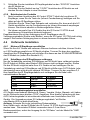
4.4.2 Kabellänge des IR Empfängers verlängern
Nur die Verkabelung zwischen IR Empfänger und IR Modul kann verlängert werden.
Die IR Kabel mit Emitter oder Blaster LEDs können nicht verlängert werden. Stellen
Sie das IR Modul möglichst nahe Ihrer A/V Geräte auf und verlängern Sie die
Verkabelung zwischen IR Empfänger und IR Modul mithilfe eines CAT5 Kabels (oder
gleichwertig) wenn nötig bis auf maximal 300 Meter. Trennen Sie den regulären 3,5
mm Anschluss des IR Empfängerkabels und verlängern Sie die Kabel nach
nachstehendem Beispiel.
IR Empfänger
CAT5-Kabel
IR Modul
Rot
Orange
+12VDC
Schwarz
Blau
GND
Gelb
Grün
STATUS
Weiß
Braun
IR DATEN
4.4.3 AVR Verbindungskabel anschließen
A/V Geräte verschiedener Marken(z.B. Denon, Yamaha, Onkyo, Marantz, etc) haben
an der Rückseite einen direkten “IR IN” Anschluss. Eine direkte Verbindung mit dem
AVR Verbindungskabel ist eine alternative Methode zum Anschließen Ihrer A/V
Geräte. Die Verwendung eines IR Verlängerungskabels *mit Emitter
oder Blaster LED) ist dann überflüssig.
Achtung; Schauen Sie in der technischen Dokumentation
Ihrer Geräte nach, ob das IR Modul des IR Control 10 XTRA direkt angeschlossen
werden kann. Die meisten IR Kabel verwenden einen 3.5 mm Mono
Buchsenanschluss, wobei der Ausgang für die "IR Daten“ und der Mantel für "GND“
verwendet wird.

IR Control 10 XTRA™
19
DEUTSCH
5 Häufig gestellte Fragen (FAQs)
Die A/V Geräte reagieren nicht auf Signale meiner Fernbedienungen.
Der IR Empfänger hat eine Empfangsempfindlichkeit von ca. 10 Metern bei einem 90
Grad Öffnungswinkel. Der Bereich hängt zudem von der verwendeten Fernbedienung
ab.
Leuchtet die “IR Daten” Leuchte am IR Empfänger fortwährend, dann wird der IR
Empfänger möglicherweise durch ein Infrarot Störsignal gestört. Achten Sie bei der
Aufstellung des IR Empfängers darauf, dass sich zwischen Empfänger und Sender
möglichst wenig Störquellen wie direkt einstrahlendes Sonnenlicht, Flachbildfernseher
(LCD, Plasma, LED), TL Beleuchtung oder Sparlampen befinden.
Der IR Empfänger ist mit manchen A/V Geräten und Modellen, die höhere IR
Frequenzen nutzen, nicht vereinbar, wie z.B. Bang&Olufsen (B&O).
Prüfen Sie, ob der IR-Empfänger und das IR-Verlängerungskabel richtig
angeschlossen und vollständig eingestöpselt sind.
Manche IR Fenster von Settop- und Satellit Boxen sind sehr empfindlich. Diese Geräte
empfangen bisweilen zu viel Infrarotstrahlung und werden auf Grund dessen nicht oder
nur schlecht funktionieren. Versetzen Sie die IR LED, sodass weniger Infrarotlicht über
das IR Fenster einstrahlt.
Sie haben noch Fragen, die im Obigen nicht beantwortet wurden? Schauen Sie dann
unter www.marmitek.com

© MARMITEK
20
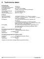
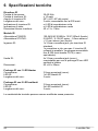
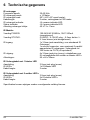
6 Technische daten
IR Empfänger
Frequenzbereich: 30-60 KHz
IR Empfänger Reichweite: ± 10 Meter
IR Empfang Winkel: 90º (+45º/-45º ab Mitte)
Kabellänge: 3 Meter, bis auf 300 Meter zu verlängern
IR Empfänger Anzeige: Ja, lila Anzeige LED
Statusanzeige: Ja, grüne Anzeige LED
Maße Empfängerkubus: 40 x 13 x 11mm
IR Modul
Speisung POWER: 100-240VAC 50/60Hz, 12VC 200mA (enthalten)
Speisung STATUS: 5-24VDC / 5-12VAC Stecker, - 5.5mm außen / + 2.1mm
innen (nicht enthalten)
IR Eingang: 1x 3,5mm Buchsenanschluss für regulären IR
Empfänger
1 x Schraubenanschluss für maximal 6 parallel
angeschlossene IR Empfänger. Zu verlängern bis zu 300
Meter über CAT5 (oder gleichwertig)
IR Ausgang 4x 3,5mm Buchsenstecker (Mono), regulierbar für IR
Verlängerungskabel mit Emitter und Blaster LED’s
Maße: 95 x 46 x 20mm
IR Verlängerungskabel mit 1 Blaster LED
Anschluss: 3,5mm Buchsenstecker (Mono)
IR LED’s: 1x IR Blaster LED
Kabellänge: 3 Meter
IR Verlängerungskabel mit 2 Emitter LED’s
Anschluss: 3,5mm Buchsenstecker (Mono)
IR LED’s: 2x IR Emitter LED’s
Kabellänge: 3 Meter
Angaben können ohne vorherige Mitteilung geändert werden.
La pagina si sta caricando...
La pagina si sta caricando...
La pagina si sta caricando...
La pagina si sta caricando...
La pagina si sta caricando...
La pagina si sta caricando...
La pagina si sta caricando...
La pagina si sta caricando...
La pagina si sta caricando...
La pagina si sta caricando...
La pagina si sta caricando...
La pagina si sta caricando...
La pagina si sta caricando...
La pagina si sta caricando...
La pagina si sta caricando...
La pagina si sta caricando...
La pagina si sta caricando...
La pagina si sta caricando...
La pagina si sta caricando...
La pagina si sta caricando...
La pagina si sta caricando...
La pagina si sta caricando...
La pagina si sta caricando...
La pagina si sta caricando...
La pagina si sta caricando...
La pagina si sta caricando...
La pagina si sta caricando...
La pagina si sta caricando...
La pagina si sta caricando...
La pagina si sta caricando...
La pagina si sta caricando...
La pagina si sta caricando...
La pagina si sta caricando...
La pagina si sta caricando...
La pagina si sta caricando...
La pagina si sta caricando...
La pagina si sta caricando...
La pagina si sta caricando...
La pagina si sta caricando...
La pagina si sta caricando...
La pagina si sta caricando...
La pagina si sta caricando...
La pagina si sta caricando...
La pagina si sta caricando...
La pagina si sta caricando...
-
 1
1
-
 2
2
-
 3
3
-
 4
4
-
 5
5
-
 6
6
-
 7
7
-
 8
8
-
 9
9
-
 10
10
-
 11
11
-
 12
12
-
 13
13
-
 14
14
-
 15
15
-
 16
16
-
 17
17
-
 18
18
-
 19
19
-
 20
20
-
 21
21
-
 22
22
-
 23
23
-
 24
24
-
 25
25
-
 26
26
-
 27
27
-
 28
28
-
 29
29
-
 30
30
-
 31
31
-
 32
32
-
 33
33
-
 34
34
-
 35
35
-
 36
36
-
 37
37
-
 38
38
-
 39
39
-
 40
40
-
 41
41
-
 42
42
-
 43
43
-
 44
44
-
 45
45
-
 46
46
-
 47
47
-
 48
48
-
 49
49
-
 50
50
-
 51
51
-
 52
52
-
 53
53
-
 54
54
-
 55
55
-
 56
56
-
 57
57
-
 58
58
-
 59
59
-
 60
60
-
 61
61
-
 62
62
-
 63
63
-
 64
64
-
 65
65


Marmitek IR Control 10 XTRA IR Extender Manuale utente
- Categoria
- Estensori AV
- Tipo
- Manuale utente