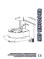
Genius Encoder Kit 230V Istruzioni per l'uso
- Categoria
- Giocattoli
- Tipo
- Istruzioni per l'uso
La pagina si sta caricando...
La pagina si sta caricando...
La pagina si sta caricando...

Instrucciones de montaje - Montageanleitung - Montage-instructies
Istruzioni di montaggio - Assembly instructions - Instructions de montage
ITALIANO
Vi ringraziamo per aver scelto il nostro prodotto. Siamo certi
che da esso otterrete tutte le prestazioni necessarie al Vostro
impiego. Tutti i nostri prodotti sono frutto di una pluriennale
esperienza nel campo degli automatismi.
Questo KIT ENCODER è stato progettato e realizzato per
l’impiego con motoriduttori scorrevoli.
L’applicazione del kit encoder richiede l’utilizzo di
un’elettronica di comando che ne permetta la
gestione.
La logica di intervento dell’encoder è spiegata nel-
le istruzioni della centrale di comando scelta.
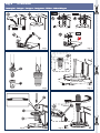
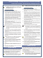
IstruzIonI dI montaggIo
Per il montaggio del kit seguire le seguenti istruzioni:
Rimuovere dalla calotta motore il tappo di copertura,
come indicato in Fig. 1, in base alla tipologia del
motore.
Fissare alla calotta motore la base encoder come
illustrato in g. 2. Nei casi A e B è necessario utilizzate
le viti in dotazione M4x15 e gli appositi distanziali.
Nel caso il motoriduttore corrisponda al caso C i due
distanziali forniti non vengono utilizzati e per la base
encoder deve essere ssata direttamente alla calotta
utilizzando le viti M4x8, fornite nel kit.
Avvitare la vite M4x10 in dotazione, g. 3 rif a, nel-
l’inserto in alluminio, g. 3 rif. b, no a battuta, come
indicato in g. 3.
Inserire l’inserto lettato con la vite nel foro dell’albero
motore, g. 4.
Utilizzando un punterulo ed un martello assicurarsi
che l’inserto in alluminio sia inserito nell’albero motore
sino a battuta, g. 4 rif. A.
Rimuovere la vite M4x10 dall’inserto lettato.
Per svitare la vite è necessario bloccare il movimento
del cancello inserendo un cacciavite, o qualsiasi
altro utensile, tra i denti del pignone come indicato
in g. 6 rif. A.
Con riferimento alla gura 5, posizionare il disco
encoder, rif. a, sull’inserto in alluminio e ssarlo con
la rondella, rif. b, e la vite M4, rif. c.
Avvitare il tutto, g. 6. Per stringere in modo corretto il
disco encoder è necessario bloccare il movimento del
cancello inserendo, tra i denti del pignone, un caccia-
vite o qualsiasi altro utensile, vedi g. 6 rif. A.
Una volta stretta la vite vericare che il disco
encoder non possa ruotare liberamente.
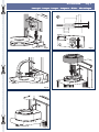
Posizionare la scheda elettronica, g. 7.
Vericare che il disco si trovi a metà del lettore, g.
8 rif. a. Se così non fosse è possibile correggere la
posizione del lettore sulla scheda, g. 8 rif. b.
Innestare il cavo sull’apposito morsetto, g. 9.
Posizionare il coperchio di chiusura, g. 10, facendo
passare il cavo all’interno dell’apposita feritoia, g.
11.
Collegare l’altra parte del cavo alla scheda di comando
del motoriduttore.
ENGLISH
Thank you for choosing our product. We are sure you will get
the performances you expect to satisfy your requirements.
1.
2.
3.
4.
5.
6.
7.
8.
9.
10.
11.
12.
13.
All our products are the result of a many years’ experience
in the eld of the automated systems.
This ENCODER KIT was designed and realised for the use
with gearmotors for sliding applications.
The encoder kit requires the use of a control board
that manages it.
The encoder operating logic is explained in the
instructions of the selected control unit.
assembly InstructIons
Refer to the following instructions to assemble the kit:
Remove the covering plug from the motor cover, as
shown in Fig. 1, according to the motor type.
Secure the encoder base to the motor cover, as
shown in g. 2. Use the M4x15 supplied screws and
the relevant spacers in the event of A and B cases.
If the gearmotor falls within the C case, both supplied
spacers are not used and the encoder base must be
directly secured to the motor cover by using the M4x8
screws – supplied with the kit.
Tighten the supplied M4x10 screw, g. 3 ref. a, into
the aluminium insert, g. 3 ref. b, until it reaches the
travel stop, as shown in g. 3.
Fit the threaded insert with the screw into the motor
shaft opening, g. 4.
By means of a punch and a hammer, make sure that
the aluminium insert has reached the travel stop inside
the motor shaft, g. 4 ref. A.
Remove the M4x10 screw from the threaded insert.
To loosen the screw just lock the gate movement
inserting a screwdriver, or any other tool, between
the pinion teeth, as shown in g. 6 ref. A.
With reference to gure 5, place the encoder disc,
ref. a, on the aluminium insert and secure it with the
washer, ref. b, and the M4 screw, ref. c.
Tighten the whole part, g. 6. To tighten the encoder
disc in a correct way, just lock the gate movement
inserting a screwdriver, or any other tool, between the
pinion teeth, see g. 6 ref. A.
After having tightened the screw, make sure that
the encoder disc cannot freely rotate.
Place the control board, g. 7.
Check if the disc is in the middle of the reader, g. 8
ref. a. If this is not the case, adjust the reader position
on the board, g. 8 ref. b.
Connect the cable on the relevant terminal, g. 9.
Place the cover, g. 10, and route the cable into the
relevant slot, g. 11.
Connect the other cable end to the gearmotor control
board.
FRANÇAIS
Nous vous remercions d’avoir choisi ce produit. Nous
sommes certains qu’il vous permettra d’obtenir les
meilleures performances pour l’usage que vous avez prévu.
Tous nos produits sont le fruit d’une longue expérience dans
le secteur des automatismes.
Ce KIT ENCODER a été conçu et réalisé pour être utilisé
avec des motoréducteurs coulissants.
L’application du kit encoder exige l’installation
d’une électronique de commande qui en
1.
2.
3.
4.
5.
6.
7.
8.
9.
10.
11.
12.
13.
La pagina si sta caricando...
La pagina si sta caricando...
La pagina si sta caricando...

Timbro rivenditore: / Distributor’s stamp: / Timbre de l’agent: / Sello del revendedor: / Fachhändlerstempel: /
Stempel dealer:
00058I0157 Rev.3
-
 1
1
-
 2
2
-
 3
3
-
 4
4
-
 5
5
-
 6
6
-
 7
7
-
 8
8


Genius Encoder Kit 230V Istruzioni per l'uso
- Categoria
- Giocattoli
- Tipo
- Istruzioni per l'uso
in altre lingue
- English: Genius Encoder Kit 230V Operating instructions
- français: Genius Encoder Kit 230V Mode d'emploi
- español: Genius Encoder Kit 230V Instrucciones de operación
- Deutsch: Genius Encoder Kit 230V Bedienungsanleitung
- Nederlands: Genius Encoder Kit 230V Handleiding
Documenti correlati
-
Genius MILORD 424 ENV 824 ENV Istruzioni per l'uso
-
Genius RAINBOW 324 524 724 C Istruzioni per l'uso
-
-
-
-
-