
ELEKTRO-NUDELKOCHER
ELECTRIC PASTA COOKER
CUISEUR À PÂTES ELECTRIQUE
CUOCIPASTA ELETTRICA
COCEDOR DE PASTA ELECTRICO
MÁQUINA DE MACARRÃO, ELÉTRICO
ELEKTRISCHE PASTAKOKER
URZĄDZENIE DO GOTOWANIA
PRODUKTÓW MĄCZNYCH, ELEKTRYCZNE
296311 / CPE91M00
Rev.-Nr:. 01-2017
INSTALLATION S-, BE DIE N UNGS-
UN D W ARTUNGSANW EISUNGEN
INSTALLATION ,OPERATING
AND MAINTENANCE NSTRUCTIO NS
MA NUEL D' INSTALLATION
D' UTILISATIO N ET D'ENTRET IEN
MA NUALE DI I NST ALLA ZIO NE
USO E MANUT E NZIONE
MA NUAL DE IN STALACIÓN
USO Y MANTEN IMIE NTO
MA NUAL DE IN STALAÇÃO,
UT ILIZAÇÃO E MANUTENÇÃO
HA NDL EIDI NG VOOR INSTALLATIE,
GE BRUIK E N O NDE RHOUD
W SKAZÓW KI DOTYCZĄ CE I NST ALACJI,
U
Ż
YTKOW ANIA I KO NSERW AC JI
DE
GB
FR
IT
ES
PT
NL
PL

TECHNISCHE ÄNDERUNGEN VORBEHALTEN!
TECHNICAL CHANGES RESERVED!
SOUS RESERVE DE MODIFICATIONS TECHNIQUES !
CI RISERVIAMO LA POSSIBILITÀ DI INTRODURRE MODIFICHE TECNICHE!
¡SE RESERVA EL DERECHO A INTRODUCIR MODIFICACIONES TÉCNICAS!
SUJEITO A ALTERAÇÕES TÉCNICAS!
TECHNISCHE WIJZIGINGEN VOORBEHOUDEN!
WPROWADZANIE ZMIAN TECHNICZNYCH ZASTRZEŻONE!
PL
IT
DE
PT
NL
ES
FR
GB

1
ENGLISH
GB
1. TABLE OF CONTENTS
1. TABLE OF CONTENTS ..................................................................................................................... 1
2. INDEX ................................................................................................................................................. 2
3. SAFETY .............................................................................................................................................. 3
4. GENERAL INFORMATION AND WARNINGS ................................................................................... 4
4.1. General guidelines ................................................................................................................... 4
4.2. Description of the appliance ..................................................................................................... 4
4.3. Index plate ................................................................................................................................ 5
4.4. Exchange of components (service technician) ........................................................................ 5
4.5. Elements and accessories ....................................................................................................... 5
4.6. Protection devices .................................................................................................................... 5
5. USE AND OPERATION ..................................................................................................................... 6
5.1. Description of the controls. ....................................................................................................... 6
5.2. Device switching on and off ..................................................................................................... 6
5.3. Filling the tank .......................................................................................................................... 7
5.4. Draining the container .............................................................................................................. 7
5.5. Guidelines on how to use the appliance .................................................................................. 7
6. CLEANING AND MAINTENANCE ..................................................................................................... 8
6.1. Guidelines on cleaning and maintenance ................................................................................ 8
6.2. Correct maintenance (service technician) ................................................................................ 8
6.3. Cleaning of the container ......................................................................................................... 8
7. TROUBLESHOOTING ....................................................................................................................... 9
8. INSTALLATION .................................................................................................................................. 9
8.1. Packaging and unpacking ........................................................................................................ 9
8.2. Installation (service technician) .............................................................................................. 10
8.3. Water connection (service technician) ................................................................................... 10
8.4. Connection to the mains (service technician) ........................................................................ 11
8.5. Installation of the appliance in a line ...................................................................................... 11
8.6. Check-up (service technician) ................................................................................................ 12
9. SETTINGS ........................................................................................................................................ 12
10. APPLIANCE DISPOSAL .................................................................................................................. 12
ATTACHMENTS ....................................................................................................................................... I

2
ENGLISH
GB
2. INDEX
A
APPLIANCE DISPOSAL 12
C
Check-up 12
Cleaning of the container 8
Connection to the mains 11
Correct maintenance 8
D
Description of the appliance 4
Description of the controls 6
Device switching on and off 6
Draining the container 7
E
Elements and accessories 5
Exchange of components 5
F
Filling the tank 7
G
General guidelines 4
Guidelines on cleaning 8
Guidelines on how to use the appliance 7
Guidelines on regular use of the appliance 7
I
Index plate 5
Installation 10
Installation of the appliance in a line 11
L
Longer interval in the use of the appliance 7
M
Maintenance 8
P
Packaging 9
Protection devices 5
S
SAFETY 3
T
TROUBLESHOOTING 9
U
Unpacking 9
W
Water connection 10

3
ENGLISH
GB
3. SAFETY
Read carefully the guidelines and
instructions in the instruction manual
before you use the appliance.
The instruction manual contains general
information on how to safely use and maintain the
appliance. Retain the manual for future reference.
Electric installation conforms to CEI EN
60335-1 and 60335-2-47 regulation.
To prevent any hazard, the damaged
mains power cable may be replaced by the
manufacturer or service personnel only.
The manufacturer took extra care when designing
and manufacturing to prevent any safety or health
hazard to the personnel operating the appliance.
Please read carefully the guidelines in the
instruction manual and instructions placed directly
onto the appliance. Above all, observe all the
safety instructions.
Do not intervene in or remove the protective
devices installed in the appliance. Non-
compliance may lead to severe safety and health
hazard against people. We recommend to perform
a few tests to know the layout and main functions
of the control panel, particularly those to switch
the appliance on and off.
The appliance is intended only for the use it has
been designed for and any other use is
considered as the use not in compliance with the
intended use.
The manufacturer is not liable for material
damage or damage to person caused by
misapplication or incorrect application of the
appliance.
Any maintenance work that requires special
technical license or special skills may be
performed by qualified personnel only.
To provide hygiene and protect foods from dirt, all
the elements that have direct or indirect contact
with the foods and all border areas must be
thoroughly cleaned. Use only the cleaning agents
intended for use in contact with food and avoid
using flammable agents or harmful to health.
After each use of the appliance make sure that all
the heating elements and control elements have
been switched off and the cable unplugged.
In case of prolonged interval in using the
appliance disconnect all power supply cables and
thoroughly clean the inside and outside elements
of the appliance.
In direct connection to the mains
the safety switch should be supplied
where wire joints dilation is large enough
to secure disconnection in category III
overvoltage, which is in accordance with
the installation rules.
In case of connecting articulated
joints to the water network with use of
construction kit use only new kit, supplied
with the device.
You must not clean the appliance with
the direct stream of water.

4
ENGLISH
GB
4. GENERAL INFORMATION AND WARNINGS
4.1. General guidelines
The manual has been edited by the manufacturer
to provide the authorized personnel with the
information necessary to work with the appliance.
We recommend the intended readers to read the
manual carefully and comply with the information.
By reading the information contained in the
manual, hazards against people health and safety
may be prevented.
Retain the manual in an easily available place
throughout the time of use of the appliance to
have access and refer to the required information
at any time.
Special symbols, described below, have been
used to stress important information or draw
attention to essential data:
Warning
Indicate important safety
instructions. You should acquire the
proper conduct to prevent hazard against
people health and safety or not to cause
any damage.
Caution
Indicate essentials technical data that
you cannot ignore.
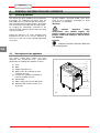
4.2. Description of the appliance
This device, called pasta cooker, has been
designed and manufactured for professional
gastronomy for cooking flour products in water.
1) Tank
2) Door
3) Height adjustable feet
4) Water valve: fills and adjusts water
amount in the tank.
5) Temperature controller knob adjusts
power of heating elements.
6) Control lights
7) Water supply: fills the tank with water
8) Minimum and maximum water level
in the tank
1
2
3
4
ID 01
7
8
5
6

5
ENGLISH
GB
4.3. Index plate
The index plate indicated in the drawing is
mounted directly onto the appliance. There are all
guidelines and information on the plate required
for safe use.
1) EAN-No.
2) Code-No. / Model-No.
3) Connection: power / supply frequence /
supply voltage
4) Date of production
5) Serial-No.
6) WEEE symbol
7) CE-marking
4.4. Exchange of components (service technician)
Before exchange of the component
switch on all the existing protection
devices.
In particular, switch off the electric
supply with the electrical potential switch.
If necessary, exchange the used components
to the original spare parts.
We are not liable for personal injury or
damage to the components that arise due to
application of other spare parts than original
or intervention into the appliance without the
manufacturer’s consent that may have altered
the safety requirements.
4.5. Elements and accessories
The device is delivered with the following
equipment:
A. Shelf for baskets.
On demand we can provide the following set of
baskets:
1. Basket 1/1
2. Basket 2/3
3. Basket 1/2
4. Basket 1/3
5. Basket 1/3 transverse
6. Basket 1/3 longitudinal
7. Basket 1/3 Ø 180
8. Basket 1/6 Ø 145
9. Basket 1/6
10. Tank lid
4.6. Protection devices
The device is equipped with the following
protection systems:
1. Safety thermostat: it blocks the electric
power supply in the case of over-heating.
When the safety thermostat is on it is indicated by
the red control light. The drawing safety the
protective thermostats layout.
Check every day that the protection
devices are mounted correctly and
operational.
ID 02
1
1
2
3
4
5
6
7

6
ENGLISH
GB
5. USE AND OPERATION
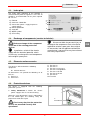
5.1. Description of the controls.
The elements controlling the essential functions
are located on the control panel of the device.
A) Temperature control knob: For
switching the heating elements on and off
B) Water valve: For filling the tank.
C) Green control light: Indicates heating of
the device.
D) Red control light: Indicates activation of
safety thermostats.
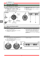
5.2. Device switching on and off
SWITCHING ON:
A) Start the automatic switch-off to turn on
the electrical connection.
B) Filling of tank is realized with use of water
valve B (see section 5.1).
C) Set the temperature control knob (A) to
desired position. We recommend to set the
temperature control knob to position 3 to
select the maximum power and limit the
heating phase time. The green control light
(B) comes on.
SWITCHING OFF
A) To switch off the electric heating elements
set the temperature control knob (A) to 0.
The control light (C) goes off.
B) Start the automatic switch-off to turn off
the electrical connection.
C) Empty the tanks as required (see
separate section).
Minimum
power symbol
Water valve
A
B
A
Maximum
power
symbol
Switch-off
symbol
B
Medium
power symbol
C
D
Operational
control lights
B
A
C

7
ENGLISH
GB
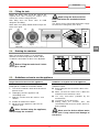
5.3. Filling the tank
Rotate the water valve to fill the tank to the
required level. After reaching the highest level
activate the electric heating elements.
After filling close the water valve to avoid
dangerous overfilling.
When water level drops below minimum open the
water valve again.
Avoid using the device with the
tank filled below the marked minimum
level.
The device may be connected to hot water supply
to reduce the heating time (max. 60°C).
5.4. Draining the container
Water may be drained with use of appropriate
collector resistant to temperature of min. 100°C.
To drain the tank rotate the drain valve (A) down.
Before filling the tank check if drain
valve (A) is closed.
5.5. Guidelines on how to use the appliance
Longer interval in the use of the appliance
When you plan not to use the appliance for the
prolonged time, follow the instructions below:
1. Turn on the automatic switch-off to disconnect
from the mains.
2. Thoroughly clean the appliance and
surrounding areas.
3. Apply the vaseline oil on the stainless steel
surfaces.
4. Perform all maintenance works;
5. Do not cover the appliance and leave the
container open.
When finished using the appliance,
always empty the container.
Guidelines on regular use of the appliance
To ensure correct use of the device follow the
guidelines below:
Before filling the tank check if the drain valve
is closed;
Make sure that the water level is above the
minimum level marked in the tank.
Use only accessories provided by the
manufacturer;
Use baskets in the correct way;
During filling the baskets take into
consideration that the pasta volume increases
during cooking.
Never use the device without water
in the tank. It may cause total damage of
the device.
CLOSED valve
ID 05
A
OPENED valve
Close
Maximum
level
Maximum
level
Open

8
ENGLISH
GB
6. CLEANING AND MAINTENANCE
6.1. Guidelines on cleaning and maintenance
Before you start maintenance
works, turn on all the mounted protective
devices.
In particular, disconnect the electric
power supply by means of the automatic
switch-off.
6.2. Correct maintenance (service technician)
Proper maintenance includes daily cleaning of all
components which have contact with food
products, and regular maintenance of drain pipes.
Careful maintenance ensures the best
performance, longer life of the appliance and
proper operation of the protective devices.
Never direct the water stream or high pressure jet
towards the appliance.
To clean the stainless steel, do not use iron wool
or iron brush as they may leave iron particles on
the surface that form rust in result of oxidation.
In the case of prolonged intervals in the use of the
appliance, apply the vaseline oil onto all the
stainless steel surfaces.
Do not use any clearing agents that
contain substances hazardous or harmful
to health (solvents, petrol. etc.).
At the end of the working day clean:
tank
baskets and other accessories
device
Regularly instruct the specialist personnel to
perform the following maintenance works:
check the electric installation;
check the safety thermostats.
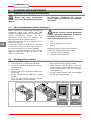
6.3. Cleaning of the container
Follow the instructions below.
Turn off the device and leave to cool down.
Turn on the switch-off to disconnect from the
electrical supply.
Drain water.
Remove and clean the baskets and basket
handles (A).
Set the heating elements (B) in the vertical
position.
Clean the tank interior using the cleaning
agent intended for contact with food.
Rinse with clean water, empty, and dry.
When finished using the device, clean the
elements with a proper agent to dissolve the
fat. We recommend to wash the accessories
in the dishwasher.
Set the heating elements (B) in the horizontal
position (operating position).
A
B
Horizontal
position
Vertical
position

9
ENGLISH
GB
7. TROUBLESHOOTING
The information below is provided to recognize
and repair any failures that may occur when
operating the appliance.
Some of the failures can be repaired by the user,
others require thorough specialist knowledge.
Such problems may be solved exclusively by the
qualified personnel.
Problem Cause Solution
The heating elements do not
heat up.
Incorrect position of the
heating element.
Check position of the heating
element in the tank (see section 6.3).
The electrical connection is not
correct.
Check the electrical connection.
Safety thermostat tripped. Reset the device (see section 4.6).
Damaged temperature control
knob.
Replace the temperature control
knob.
Contact the service company.
Incorrect water connection.
No water flow after opening
the valve.
Check the water connection.
Contact the service company.
8. INSTALLATION
8.1. Packaging and unpacking
During unloading and when installing the
appliance follow the information from the
manufacturer placed directly on the packaging
and in this manual.
To lift and transport the product plan to use a fork
lift or stacker, and pay attention to even weight
distribution to avoid a risk of tilting of the
packaging (avoid excessive incline!).
When using the lifting equipment
pay attention to the mains cable, water
supply and discharge pipes and feet
position.
The packaging consists of the carton packaging
and wooden pallet. There are symbols printed on
the carton packaging that according to the
international agreements inform about the
regulations to follow when loading and unloading,
transporting and storing the appliance.
When collecting the goods check if the packaging
is complete and has not been damaged during
transport.
Any damage should be immediately reported to
the shipping company.
Unpack the appliance as soon as possible to
check if the appliance is not damaged.
Do not use a sharp object to cut the carton box. It
may damage the stainless steel inside the box.
Remove the carton packaging from bottom to top.
When unpacked check if the appliance is
according to the order.
In case of any difference inform the sales agent
immediately.
Do not store the packaging
materials (nylon bags, polystyrene foam,
clips ...) in the reach of children!
Remove the protective PVC layer from the out
and inner surfaces. If possible, do not use any
metal tools.
THIS
SIDE UP
CAUTION
GLASS
KEEP DRY

10
ENGLISH
GB
8.2. Installation (service technician)
All the stages of the installation must be carefully
planned.
The location should be equipped with all supply
connections and production waste outlet. The
location should also be properly lit and comply
with all hygiene and sanitary requirements
according to the binding regulations.
The appliance should be installed with the
minimum 5 cm clearance from the wall, if the
wall is not resistant to the minimum temperature
of 150 °C.
Locate the appliance in the horizontal position by
adjusting the single feet.
To ensure the correct operation of
the appliance, the appliance must be
installed and operated in the thoroughly
ventilated room only.
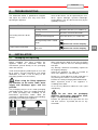
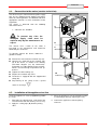
8.3. Water connection (service technician)
The installation is performed by connecting the
connection pipe of the device to the water network
pipe. Install the cut-off valve (A) on the connection
to stop the water supply when required. Install
appropriate filters after that valve.
Connect potable water to the
device. Limit values for the potable water
specified by the European Union are listed
in the table.
Description Value
Pressure 150-300 kPA
1.5-3 bar
pH 6.5-8
Hardness 8-15°F
(80-150 ppm CaCO3)
Minerals <1500 mg/l
Iron < 0.2 mg/l
Manganese <0.05 mg/l
Chlorine <0.25 mg/l
Sulphur <0.25 mg/l
In case of connecting to the water
network with use of construction kit use only
new kit, supplied with the device.
ID 12
ID 06

11
ENGLISH
GB
8.4. Connection to the mains (service technician)
The device may be connected to the power supply
only by the authorized and qualified personnel,
when the valid regulations are followed and when
appropriate material is used in accordance to the
regulations.
The device is delivered with the following
connection values:
380-415V 3N~ 50-60Hz
To prevent any risks the
damaged supply cable must be
replaced only by the manufacturer or
expert.
The correct cross section of the cable is
presented in the attachments and should be
decided by the electrician.
To correctly connect the device, follow the
guidelines below:
Remove the cover from the terminal strip (A).
Connect the switch-off to the terminal strip
(B) of the device, as shown in the drawing
and block diagram (see the attachment).
Preferably use cable H07RN-F type or better,
which is resistant to high temperature min. up
to 80 °C.
Tighten the cable endings (C).
Replace the terminal strip cover.
The device is equipped with the equipotential
clamp (M).
Respectively to the clamp used a special
sticker is envisaged: .
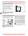
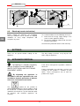
8.5. Installation of the appliance in a line
To fix the appliance in a line (neighbouring) follow
the steps:
1. Dismantle the control panel, and remove the
cast iron frame from the chimney if necessary.
2. Apply the sealing tape (A) onto the joining
sides.
3. Place the appliances next to each other and in
a horizontal position (by adjusting the feet).
4. Connect the appliances with the joining
elements.
M
A
B
C

12
ENGLISH
GB
8.6. Check-up (service technician)
Before starting the appliance the installation
check-up should be run to evaluate the working
conditions of every single component and
recognize any errors.
It is recommended to run the following check-ups:
1. Check that the energy supply voltage is the
same as of the appliance voltage.
2. Turn on the automatic switch-off to check the
electrical connections.
Check that the protection devices work correctly.
9. SETTINGS
There are no special default settings of the
appliance.
The only settings are those set up by the user
while using the appliance.
10. APPLIANCE DISPOSAL
The appliance is marked in conformity
with the European Directive 2002/96/EG
WASTE ELECTRICAL AND ELECTRONIC
EQUIPMENT (WEEE).
By disposing the appliance in
accordance with the regulations the user
contributes towards prevention of adverse
effects on environment and health.
The symbol on the product or
attached manual indicates that the product cannot
be considered as ordinary household waste and
should be transferred to a special collection point
for electrical and electronic appliances for
recycling.
Local waste management regulations should be
observed.
Further information on procedure, reusing and
recycling of the product is available in local
offices, waste management unit or with the
product sales agent.
A
A
B
C
C

I
ANLAGEN
ATTACHMENTS
ANNEXES
ALLEGATI
ANEXOS
ANEXOS
BIJLAGEN
ZAŁĄCZNIKI

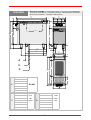
II

III
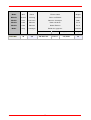
Modello
Vasca Potenza Dati elettrici Peso
Model
Well Power Electrical data Weight
Modelle
Becken Leistung Daten zur Elektrik Gewicht
Modèle
Cuve Puissance Données électriques Poids
Modelo
Cuba Potencia Datos eléctricos Peso
Modelo
Cuba Potencia Dados Elétricos Peso
Model
Kuip Vermogen Elektrische gegevens Gewicht
kW V Hz Supply cable kg
CPE91M00 40 9,6 380-415V 3N~
50-60 Hz
5x1,5mm² 56

IV
Allacciamento Elettrico
Electric Connection
Branchement Electrique
Elektroanschluss
Conexiòn elètrica
Ligação Elétrica
Elektrische aansluiting
75
905
950
510
150
255
400
150100
200 200
508
400
119.5
905
950
277.5
30846 46
243.5
24080 80
150
60
180
510
150
900
750
25
85
655
715
55
95
540
580
CPE91M00
9.6 kW
ANSCHLUSSSCHEMA
- CONNECTION CARD - FICHE DES RACCORDEMENTS -
SCHEDA ALLACCIAMENTI - FICHA DE ENLACES - ESQUEMA DAS CONEXÕES -
PLAN AANSLUITINGEN - SCHEMAT PODŁĄCZENIA
Allacciamento acqua Scarico acqua
Water Input
R 1/2"
Water Drain
1" GAS
Entrèe Eau
UNI
Vidage Eau
ISO 7/1
Wassereinzug
ISO 7/1
Wasserabfluss
(ø33)
Conexiòn Agua Evacuacion Agua
Ligação Água Descarga Água
Wateraansluiting Waterafvoer

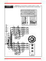
V
111 60825
REVISION 05
SCHALTPLAN
-
ELECTRIC DIAGRAM – SCHÉMA ÈLECTRIQUE - SCHEMA
ELETTRICO - ESQUEMA ELÉCTRICO - ELEKTRISCH SCHEMA - SCHEMAT IDEOWY
2
3
1
LR = LAMPADA ROSSA
LV = LAMPADA VERDE
S1 = LIMITATORE DI TEMPERATURA
C1 = CONTATTORE
MCR = MICROINTERRUTTORE
B1 = COMMUTATORE
ALIMENTAZIONE
700 900
49.44015.712
55.32532.805
R1,R2,R3 = RESISTENZE
2600 watt (3x)
230V 11.3A
3200 watt (3x)
230V 13.9A
SIGNAL LUX Mod 21.3 230V
(T120) Silicon Leads
(T120) Silicon Leads
SIGNAL LUX Mod 21.3 230V
0,1,2,3 16A 250V T150
T=160°C -17K 400V 30A
OMRON
J7KN-14D-10
CABLAGGIO
CABLAGGIO LAMPADE
CAVO H05SJ-K
Section 1 mmq
M = MORSETTIERA
FV122 6 POLI - 40 A - 450 V
CAVO H05SJ-K
Section 2.5 mmq
J7KN-22D-10
49.44015.712
380-415V 3+N~ 50-60Hz
55.32524.160
T=135°C -12K 400V 30A
380-415V 3N~ 50-60Hz
CPE71 : 5Gx1.5 mmq 11.3 A
CPE72 : 5Gx2.5 mmq 22.6 A
CPE91 : 5Gx1.5 mmq 14 A
CPE92 : 5Gx4mmq 28 A
OMRON
J7KN24 J7KN24
ALLEN BRADLEY
100-M09N A3 100-C16 KF10
P3P2P1
321
12 22
11 21
24
M1
14 2 4
13 1 3
R2R1
M2
P4
4
32
31
6
5
R3
B1
S1
C1
L1 L2 L3 N N
M
PE
2
P4 P3 P2 P1
4 3 2 1
P4 P3 P2 P1
4 3 2 1
P3 P2 P1
2 1
31
B1
P4 P3 P2 P1
4 3 2 1
P4
4 3
0
P3P2P1
321
12 22
11 21
24
14 2 4
13 1 3
R2R1
P4
4
32
31
6
5
R3
B1
S1
C1
A1
A2
LV
LR
MCR
1
3.
A1
A2
LV
LR
MCR
1
3.
M2 M2 M2 M2 M2
M1
CESUP INF CESUP INF
AM51614D53NAT
PANASONIC

VI
NOTE
La pagina si sta caricando...
La pagina si sta caricando...
-
 1
1
-
 2
2
-
 3
3
-
 4
4
-
 5
5
-
 6
6
-
 7
7
-
 8
8
-
 9
9
-
 10
10
-
 11
11
-
 12
12
-
 13
13
-
 14
14
-
 15
15
-
 16
16
-
 17
17
-
 18
18
-
 19
19
-
 20
20
-
 21
21
-
 22
22


