
Form No. 712-69 Multi Language (Rev. 2/19/18) © 2018 Bobrick Washroom Equipment, Inc.
INSTALLATION INSTRUCTIONS
QuietDry™ Series, TrimDry™
SURFACE-MOUNTED ADA DRYER
B-7120 White Painted Steel or B-7128 Stainless Steel
Installation Instructions Surface-Mounted Hand Dryer ...............................................Pages 2 & 3
Instrucciones De Instalación Secadores De Manos Bobrick
Montados Sobre La Pared Tipo ......................................................................................Pages 4 & 5
Einbauanleitung Bobrick -Hände
Für Aufputzmontage ......................................................................................................Pages 6 & 7
Notice D’Installation Sèche-Mains Bobrick
Montés En Surface ..........................................................................................................Pages 8 & 9
Istruzioni Per L’installazione Asciugamani Bobrick ................................................Pages 10 & 11
表面安装式自动感应干手机/干发机安装说明书 ................................................Pages 12 & 13
Warranties ...................................................................................................................Pages 14 & 15
1

WARNING: TURN ELECTRICAL POWER SUPPLY OFF BEFORE
MAKING ELECTRICAL CONNECTIONS.
DRYER MUST BE GROUNDED (EARTHED).
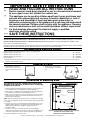
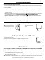
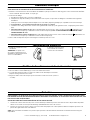
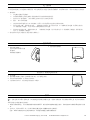
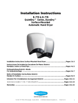
x 4
Ø 5/16" 8mm
1. 2. 3.
Ø7/8" 22mm
Hole for between wall wiring
Flange cutout for
surface mounting
9-1/4" 235mm
7-3/4" 197mm
13-25/32" 350mm
13-19/32" 345mm
Ø7/8" 22mm
Hole for between wall wiring
Form No. 712-69 Multi Language (Rev. 2/19/18) © 2018 Bobrick Washroom Equipment, Inc.
Electrical Characteristics
Recommended Mounting Heights
Removal of Cover
Installation of Mounting Base
IMPORTANT SAFETY INSTRUCTIONS
* READ AND FOLLOW ALL INSTRUCTIONS
** Electric warm air hand dryer intended for use in a household environment
by non-expert users. Not suitable for outdoor use.
*** This appliance can be used by children aged from 8 years and above and
persons with reduced physical, sensory or mental capabilities or lack of
experience and knowledge if they have been given supervision or
instruction concerning use of the appliance in a safe way and understand
the hazards involved. Children shall not play with the appliance. Cleaning
and user maintenance shall not be made by children without supervision.
**** If a fault develops disconnect the electrical supply, a qualified
electrician should be called.
*****
SAVE THESE INSTRUCTIONS
2
Distance from floor to bottom mounting screw holes of mounting base.
Children's Washrooms, ages 3-4 .............................................................................................................................................................. 36'' (915mm)
Children's Washrooms, ages 5-8 .............................................................................................................................................................. 40'' (1015mm)
Children's Washrooms, ages 9-12 ............................................................................................................................................................ 44'' (1120mm)
Universal Design ......................................................................................................................................................................................48'' (1219mm)
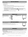
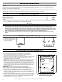
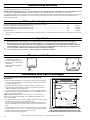
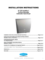
1. Start installation of dryer by
removing cover. Remove two
screws, from the bottom of the
dryer.
1. Hold the Installation Template against the wall in the desired location of
the installed dryer. See recommended mounting heights above.
2. Make sure line on template representing bottom of dryer mounting base
is horizontal and located at the desired height above floor.
3. Mark center of four mounting screw holes and hole for entry of electrical
wiring if electrical supply is concealed in wall and will enter dryer from
back through mounting base.
NOTE: Surface-mounted electrical supply entry is located in the lower right
corner of the mounting base. Surface-mounted supply cable should be fitted
in a conduit.
4. For brick, stone, and concrete walls drill four 0.315" (8mm) holes to suit
wall plugs 0.315" (8mm) x 1-1/4" (45mm) and screws#10 (4.8mm) x 2"
(50mm) long (provided). See template for wall plug and screw
installation details.
5. For plaster or dry wall construction, provide concealed backing to
comply with local building codes and secure with four #10 (M4.8) round-
head sheet-metal screws, or 3/16'' (5mm) toggle bolts (not furnished).
6. Fasten mounting base securely to wall.
* Bobrick automatic hand dryers should be installed at least 15" (380mm) above any projection or horizontal surface which may interfere with the
operation of the automatic sensor.
Model B-7120 White Painted Steel Cover and B-7128 Stainless Steel Cover, 115V AC, 15 Amp, 1725 Watts, 50/60 Hz, Single Phase, cULus listed.
Model B-7120 White Painted Steel Cover and B-7128 Stainless Steel Cover, 208–240V AC, 6.8-7.8 Amp, 1400-1900 Watts, 50/60 Hz, Single
Phase; cULus listed, VDE and CE marked.
Installation instructions and template provide information that will assist in the installation of the Bobrick B-7120 and B-7128 115V, B-7120 and B-7128
208-240V. Retain Installation Instruction Sheet for important maintenance instructions and warranty information.
2. Rotate bottom of cover away
from mounting base and then lift
up.
FOR PROPER ELECTRICAL CONNECTIONS, CHECK LOCAL
BUILDING CODE. UNIT MUST BE INSTALLED BY A QUALIFIED
LICENSED ELECTRICIAN

Form No. 712-69 Multi Language (Rev. 2/19/18) © 2018 Bobrick Washroom Equipment, Inc.
Electrical Connection
Check Dryer Operation
Maintenance
Replace Cover
3
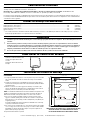
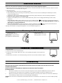
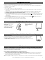
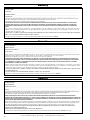
1. Fit cover over mounting base.
NOTE: Four sides of cover overlap the
mounting base and should be flush with
the sides, top and bottom of the mount-
ing base.
2. Replace and tighten two screws,
on the bottom to secure cover to
mounting base.
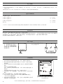
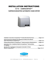
1. Turn electrical power supply on.
2. Position hands under air-outlet, within 4'' (100mm) of the bottom of the dryer.
3. Dryer should turn on. Warm air should blow from air-outlet. Drying time less than 25 seconds.
4. Remove hands from under air-outlet and dryer should stop (within 2 seconds).
FOR PROPER ELECTRICAL CONNECTIONS, CHECK LOCAL BUILDING CODE. UNIT MUST BE INSTALLED BY A QUALIFIED
LICENSED ELECTRICIAN
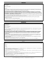
1. Connect dryer to nearest distribution panel. Use wire as required by local electrical code. In the United States and Canada
use No. 12 wire or larger.
2. Wiring Instructions:
a. This appliance is intended for connection to fixed wiring.
b. A fused means for disconnection in all poles must be provided in the fixed wiring in accordance with the wiring rules.
c. Check that the electrical rating shown on the Hand Dryer (rating label) is compatible with the electrical supply.
d. WARNING: THIS PRODUCT MUST BE EARTHED.
e. Installation and wiring must conform to current IEE Regulations (UK), local or appropriate regulation (other countries).
f. For 115 Volt Dryers: Connect ground/earth supply the terminal marked , the Live supply to terminal marked L and
neutral supply to terminal marked N. A DEDICATED LINE IS REQUIRED FOR EACH 115 VOLT DRYER.
g. For 208–240 Volt Dryers: Connect ground/earth supply the terminal marked and the 208-240 Volt wires to terminals
marked L (L1) and N (L2).
3. Secure electrical wire in strain relief clamp provided on mounting base.
WARNING: MOTOR LAMINATIONS ARE LIVE. TURN ELECTRICAL POWER SUPPLY OFF BEFORE DOING ANY
MAINTENANCE OR SERVICE TO DRYER. DRYER MUST NOT BE OPERATED UNLESS COVER IS IN PLACE.
FOR PROPER ELECTRICAL CONNECTIONS, CHECK LOCAL BUILDING CODE. UNIT MUST BE INSTALLED BY A QUALIFIED
LICENSED ELECTRICIAN
1. Exterior of cover should be cleaned with a damp cloth to remove dust and surface dirt. Do not use abrasive agents or solvents as
they may permanently damage surface of cover.
2. At least once every 6 months remove cover. Using a small brush or vacuum, clean out buildup of dust and lint from air-intake
grille and baffle.
NOTE: if dryer is installed where there is a lot of dust and dirt in the air, the interior of the dryer should be cleaned out more
frequently.

ADVERTENCIA: DESCONECTAR LA ALIMENTACIÓN DE RED
ANTES DE HACER LAS CONEXIONES ELÉCTRICAS.
EL SECADOR DEBE ESTAR CONECTADO A TIERRA.
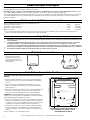
x 4
Ø 5/16" 8mm
1. 2. 3.
9-1/4" 235mm
7-3/4" 197mm
13-25/32" 350mm
13-19/32" 345mm
Recorte del reborde
para montar en la pared
Ø7/8" 22mm
Agujero para el cableado que atraviesa la pared
Ø7/8" 22mm
Agujero para el cableado que atraviesa la pared
Form No. 712-69 Multi Language (Rev. 2/19/18) © 2018 Bobrick Washroom Equipment, Inc.
Características Eléctricas
Alturas de Montaje Recomendadas
Cómo Quitar La Cubierta del Secador
Instalación de la Base de Montaje
Importante
4
1. Coloque la plantilla de Instalación contra la pared en la posición deseada
del secador instalado. Consulte las alturas de montaje recomendadas
arriba.
2.
Asegúrese de que la línea en la plantilla que representa la parte inferior
de la base de montaje del secador esté a nivel horizontal y situada a la altura
deseada del suelo.
3. Marcar el centro de los cuatro agujeros de montaje con tornillos y del
agujero de entrada del cableado eléctrico si la alimentación está oculta en
la pared y entra el secador atrás por la base de montaje.
NOTA: La entrada de la alimentación eléctrica montada en la superficie está
situada en la esquina derecha inferior de la base de montaje. El cable de
alimentación montado en la superficie debe colocarse en un conducto.
4. En el caso de paredes de ladrillo, piedra y hormigón, perforar cuatro
agujeros de 0.315" (8 mm) para acomodar las conexiones a la pared de
0.315" (8 mm) x 1-1/4" (45 mm) y tornillos #10 (4.8 mm) x 2" (50 mm) de
longitud (provistos).
Consulte la plantilla para obtener información detallada sobre el montaje
en pared y la instalación de tornillos.
5. En construcciones de lamina de yeso, usar una placa interna que cumpla
con los códigos de construcción locales y fijar con cuatro tornillos tamaño
#10 (M4.8) de cabeza redonda para chapa o usar pernos fijadores de
palanca 3/16'' (5 mm) (no provistos).
6. Fijar la base firmemente a la pared.
1. Comenzar la instalación del secador
quitando la cubierta. Retirar los dos
tornillos de la parte inferior del
secador.
Separar la cubierta de la base de
montaje.
Distancia desde el suelo a los agujeros para tornillos de montaje inferiores de la base de montaje.
Baños para niños, de 3 a 4 años ..............................................................................................................................................36'' (915 mm)
Baños para niños, de 5 a 8 años ..............................................................................................................................................40'' (1015 mm)
Baños para niños, de 9 a 12 años ............................................................................................................................................44'' (1120 mm)
Diseño Universal ......................................................................................................................................................................48'' (1219 mm)
* Los secadores de manos automáticos Bobrick deben instalarse por lo menos a 15" (380 mm) de distancia sobre toda proyección o superficie
horizontal que pueda interferir con la operación del sensor automático.
Modelo B-7120 con Cubierta de Inoxidable Pintada en Blanco y Modelo B-7128 con Cubierta de Acero Inoxidable, de 115 V de CA,
15 Amp, 1725 vatios, 50/60 Hz, monofásicos, clasificados UL.
Modelo B-7120 con Cubierta de Inoxidable Pintada En Blanco y B-7128 con Cubierta de Acero Inoxidable, de 208–240 V de CA,
6.8-7.8 Amp, 1400-1900 vatios, 50/60 Hz, monofásicos, clasificados UL, aprobados por VDE, y marcado CE.
Las instrucciones de instalación y la plantilla proporcionan información que sirve para instalar los secadores Bobrick B-7120 y B-7128 de 115 V, y
los B-7120 y B-7128 de 208-240 V. Guarde la hoja de instrucciones de instalación para obtener instrucciones importantes sobre el mantenimiento
e información sobre la garantía.
* Secamanos por aire caliente. Diseñado para su uso en el hogar por parte de usuarios no expertos. No es adecuado para su uso al
aire libre.
** Este secamanos puede ser usado por niños de 8 años de edad y mayores y personas con capacidad física, sensorial o mental
reducida o personas con falta de experiencia o conocimiento que hubieren recibido supervisión o instrucciones en lo referente al
uso del secamanos en forma segura y que entiendan posibles riesgos supuestos. Los niños no deben jugar con este equipo. La
limpieza y mantenimiento del secamanos no debe ser realizado por niños sin supervisión adulta.
*** En caso de que ocurriera un defecto, desconecte el suministro eléctrico y llame a un electricista cualificado.
LA INSTALACIÓN DEBE SER SUPERVISADA POR UN ELECTRICISTA
CUALIFICADO.

Form No. 712-69 Multi Language (Rev. 2/19/18) © 2018 Bobrick Washroom Equipment, Inc.
Conexión Eléctrica (cont.)
Verificación de la Operación del Secador
Mantenimiento
Restitución de la Cubierta
5
1. Conectar la alimentación eléctrica.
2. Situar las manos debajo de la salida de aire, a 4'' (100 mm) de la parte inferior del secador.
3. El secador debe encenderse. Saldrá aire caliente de la salida de aire.
4. Al retirar las manos de la salida de aire, el secador debe pararse (después de 2 segundos).
1. Instalar la cubierta sobre la base
de montaje.
NOTA : Los cuatro lados de la cubierta
se superponen con la base de montaje
y deben estar al ras con los cuatro
lados de la base de montaje.
2. Reponer y ajustar los dos
tornillos en la parte inferior para
fijar la cubierta sobre la base de
montaje.
PARA TENER LAS CONEXIONES ELÉCTRICAS CORRECTAS, CONSULTE EL CÓDIGO DE CONSTRUCCIÓN LOCAL. LA UNIDAD LA DEBE
INSTALAR UN ELECTRICISTA CAPACITADO CALIFICADO.
1. Conectar el secador al tablero de distribución más cercano. Usar el tipo de cable exigido por el código eléctrico local. En los Estados Unidos y
Canadá, usar alambre #12 o más pesado.
2. Instrucciones de cableado:
a. Este secamanos esta diseñado para su conexión a un cableado eléctrico fijo.
b. El cableado fijo debe incorporar un dispositivo interruptor de fusibles, para desconexión de todos los polos, según las normas de cableado.
c. Verifique que la potencia eléctrica indicada en el Secamanos (véase la etiqueta de potencia eléctrica) es compatible con el suministro eléctrico.
d. ADVERTENCIA: ESTE PRODUCTO DEBE ESTAR CONECTADO A TIERRA.
e. La instalación y el cableado deben cumplir con los requisitos exigidos por las Normas IEE existentes (Reino Unido) o las normas locales o
apropiadas (otros países).
f. Secadores de 115 voltios: Conecte el suministro a tierra al terminal marcado , el suministro eléctrico Con Corriente al terminal marcado
(L) y el Neutro al terminal marcado (N). SE NECESITA UNA LÍNEA DEDICADA PARA CADA SECADOR DE 115 VOLTIOS.
g. Secadores de 208-240 voltios: Conecte el suministro a tierra al terminal marcado , el suministro eléctrico Con Corriente al terminal
marcado (L) y el Neutro al terminal marcado (N).
3. Sujetar el cable eléctrico usando la abrazadera de alivio de tensión provista en la base de montaje.
ADVERTENCIA: TENER EN CUENTA QUE LAS LAMINACIONES DEL MOTOR ESTÁN BAJO TENSIÓN. DESCONECTAR LA ALIMENTACIÓN
DE RED ANTES DE HACER CUALQUIER TRABAJO DE REVISIÓN O MANTENIMIENTO DEL SECADOR. NO OPERAR EL SECADOR SIN
TENER LA CUBIERTA INSTALADA.
LA INSTALACIÓN DEBE SER SUPERVISADA POR UN ELECTRICISTA CUALIFICADO.
1. Se debe limpiar el exterior de la cubierta con un paño húmedo para quitar cualquier polvo o suciedad. No usar agentes abrasivos ni solventes
porque pueden dañar permanentemente la superficie de la cubierta.
2. Al menos cada seis meses, quitar la tapa y limpiar el secador con un cepillo pequeño o con un aspirador, y eliminar cualquier acumulación de
polvo en la rejilla de entrada y el deflector.
NOTA : Si se ha instalado el secador en un sitio de mucho polvo y suciedad en el aire, se debe limpiar el interior del secador con mayor frecuencia.

HINWEIS: VOR MONTAGE NETZANSCHLUß TRENNEN.
TROCKNER MUSS GEERDET WERDEN.
x 4
Ø 5/16" 8mm
1. 2. 3.
Ø7/8" 22mm
Loch für die Wandverkabelung
Aussparung für elektrischen Zugang - Aufputz ! !
9-1/4" 235mm
7-3/4" 197mm
13-25/32" 350mm
13-19/32" 345mm
Ø7/8" 22mm
Loch für die Wandverkabelung
Form No. 712-69 Multi Language (Rev. 2/19/18) © 2018 Bobrick Washroom Equipment, Inc.
Elektrische Kennzeichen
Entfernung der Abdeckung
Installation der Befestigungsplatte
Empfohlene Montagehöhe
Wichtig
6
1. Bitte verwenden Sie die Schablone für die Montage. Beachten Sie bitte die
entsprechende Montagehöhe Halten Sie die Schablone gegen die Wand am
gewünschten Ort des Siehe empfohlene Aufstellhöhen oben.
2. Vergewissern Sie sich, daß die Linie auf der Vorlage, Schablonde, die die Unterkante
der Befestigungsplatte des Trockners darstellt, horizontal ist und sich auf der
gewünschten Höhe über dem Boden befindet.
3. ANMERKUNG: Erfolgt der elektrische Zugang über ein Aufputz-Kabel, führen Sie ihn
bitte durch die rechte untere Aussparung an der Befestigungsplatte. Man markiere
die Mitte von vier Befestigungsschraubenlöchern und das Loch für den Zugang der
elektrischen Kabel, wenn eine elektrische Versorgung in der Wand verborgen ist, und
von hinten durch die Markieren Sie die Löcher für die Befestigungsschrauben, sowie
die Öffnug (-en) für den elektrischen Zugang (Unterputz !!!) Befestigungsplatte in den
Trockner geführt wird.
ANMERKUNG: Der elektrische Versorgungszugang auf der Oberfläche
montiert, befindet sich an der rechten unteren Ecke der Befestigungsplatte. Der
oberflächenaufgestellte Versorgungskabel sollte in eine Leitung untergebracht werden.
4. Bei Ziegelstein-, Stein-, und Betonwänden müssen vier 0,315" (8mm) Löcher
gebohrt werden, damit Wanddübel 0,315" (8 mm) x 1-1/4" (45mm) und Schrauben#10
(4.8mm) x 2" (50mm) lang (mitgeliefert) passen. Siehe Vorlage für Wanddübel- und
Schraubeninstallations details.
5. Für Mörtel- oder Trockenbauwandkonstruktion, gemäß der örtlichen Baurvorschriften
Baurvorschriften entsprechende Unterkonstruktion herstellen und mit vier #10 (M4.8)
Rundkopf-Metallschrauben oder 3/16'' (5mm) Bolzen (nicht mitgeliefert) zu sichern.
6. Befestigungsplatte an eine Mauer sicher anbringen.
1. Lösen die beiden Schrauben
an der Unterseite des Trockner.
Entfernen Sie die Abdeckung von
der Befestigungsplatte.
Entfernung der unteren Befestigungsschraubenlöcher der Befestigungsplatte zum Boden.
Kinderwaschräume, Alter 3-4 ...................................................................................................................................................36'' (915mm)
Kinderwaschräume, Alter 5-8 ...................................................................................................................................................40'' (1015mm)
Kinderwaschräume, Alter 9-12 .................................................................................................................................................44'' (1120mm)
allgemein ..................................................................................................................................................................................48'' (1200mm)
* Bobricks automatische Händetrockner sollten mindestens 15" (380 mm) oberhalb etwaiger Projektionsflächen horizontalen Oberflächen installiert
werden, die die Funktion des automatischen Sensors beinträchtigen könnten.
Model B-7120 weiss lackierte Edelstahlabdeckung und B-7128 Edelstahlabdeckung, 115V AC, 15 A, 1725 Watt, 50/60 Hz, einphasig, cULus
aufgeführt.
Model B-7120 weiss lackierte Edelstahlabdeckung und B-7128 Edelstahlabdeckung, 208-240V AC, 6.8-7.8 A, 1400-1900 Watt, 50/60 Hz,
einphasig, cULus aufgeführt, VDE, CE- Zeichen.
Installationsanweisungen und Vorlage beinhalten Informationen, die bei der Installation des Bobrick B-7120 und B-7128 115V, B-7120 und B-7128
208-240V helfen. Die Installationsanweisung für wichtige Wartunghinweise und Garantieninformationen aufbewahren.
* Warmluft-Händetrockner. Gedacht zur Nutzung durch Normalverbraucher in Haushalten. Nicht geeignet für den Einsatz im Freien.
** Dieses Gerät kann von Kindern ab 8 Jahren und Personen mit eingeschränkten körperlichen, sensorischen oder geistigen
Fähigkeiten oder mangelnder Erfahrung und Kenntnisse benutzt werden, wenn sie während der Nutzung überwacht werden oder in
der sicheren Nutzung des Gerätes unterwiesen wurden und die damit verbundenen Gefahren verstehen. Kinder dürfen nicht mit dem
Gerät spielen. Reinigung und Benutzerpflege dürfen nicht unbeaufsichtigt von Kindern durchgeführt werden.
*** Wenn ein Fehler auftritt, muss das Gerät von der Stromversorgung getrennt und ein qualifizierter Elektriker darüber informiert
werden.
DIE INSTALLATION MUSS VON EINEM QUALIFIZIERTEN ELEKTRIKER DURCHGEFÜHRT WERDEN.

Form No. 712-69 Multi Language (Rev. 2/19/18) © 2018 Bobrick Washroom Equipment, Inc.
Elektrischer Anschluß
Prüfung des Trocknerbetriebs
Instandhaltung
Ersetzung der Abdeckung
7
1. Strom einschalten.
2. Hände etwa 10 cm unter den Luftauslaß halten.
3. Der Trockner sollte einschalten. Warme Luft sollte von der Luftaustrittsöffnung blasen. Trocknungszeit unter
25 Sekunden.
4. Bei Zurückziehen der Hände von der Luftaustrittsöffnung sollte der Trockner (innerhalb 2 Sekunden) stoppen.
1. Die Abdeckung an der
Befestigungsplatte anbringen.
ANMERKUNG: Abeckung umschließt
Befestigungsplatte umlaufend bündig.
2. Abdeckung mittels zwei
Schrauben an der Unterseite mit
Befestigungsplatte verschrauben.
FÜR EINEN ORDNUNGSGEMÄSSEN ELEKTRISCHEN ANSCHLUSS SEHEN SIE BITTE DIE ÖRTLICHEN BAUVORSCHRIFTEN EIN. DAS
GERÄT MUSS VON EINEM QUALIFIZIERTEN UND DAZU BEFÄHIGTEN ELEKTRIKER EINGEBAUT WERDEN.
1. Schließen Sie den Trockner an der nächstgelegenen Verteilertafel an. Verwenden Sie die Drähte den örtlichen Vorschriften entsprechend. In den
USA und Kanada verwenden Sie Draht #12 oder größer.
2. Verdrahtungsanleitung:
a. Dieses Gerät ist zum Anschluss über feste Verkabelung gedacht.
b. Eine mit Sicherung versehene Vorrichtung zur Unterbrechung an allen Polen muss in der Festverdrahtung den Verdrahtungsvorschriften
entsprechend angebracht sein.
c. Überprüfen Sie, dass die auf dem Handtrockner angegebene Nennleistung (Typenschild) mit der elektrischen Zuleitung kompatibel ist.
d. WARNUNG: DIESES PRODUKT MUSS GEERDET SEIN.
e. Installation und Verkabelung müssen den aktuellen IEE-Richtlinien (UK), örtlichen oder einschlägigen Bestimmungen (andere Länder)
entsprechen.
f. Für Trockner mit 115 Volt: Den Masse-/Erdanschluss mit der mit dem Erdungssymbol gekennzeichneten, den Phasenleiter mit der mit
(L) gekennzeichneten und den Neutralleiter mit der mit (N) gekennzeichneten Klemme verbinden. FÜR JEDEN TROCKNER MIT 115 VOLT IST
EINE SPEZIELLE LEITUNG ERFORDERLICH.
g. Für Trockner mit 208-240 Volt: Den Masse-/Erdanschluss mit der mit dem Erdungssymbol gekennzeichneten, den Phasenleiter mit
der mit (L) gekennzeichneten und den Neutralleiter mit der mit (N) gekennzeichneten Klemme verbinden.
3. Befestigen Sie den Draht an der Zugentlastungsklemme, die an der Grundplatte angebracht ist.
WARNHINWEIS: ANKERFOLIEN SIND STROMFÜHREND. SCHALTEN SIE DIE STROMVERSORGUNG AUS, BEVOR IRGENDWELCHE
WARTUNGS- ODER INSTANDHALTUNGSARBEITEN AM TROCKNER AUSGEFÜHRT WERDEN. DER TROCKNER DARF NUR BE
ANGEBRACHTEM GEHÄUSE
DIE INSTALLATION MUSS VON EINEM QUALIFIZIERTEN ELEKTRIKER DURCHGEFÜHRT WERDEN.
BETRIEBEN WERDEN.
1. Das Äußere des Gehäuses muss mit einem feuchten Tuch abgewischt werden, um Staub und Oberflächenschmutz zu entfernen.
Verwenden Sie keine Scheuermittel oder Lösungsmittel, da sie die Gehäuseoberfläche permanent beschädigen könnten.
2. Nehmen Sie das Gehäuse mindestens alle 6 Monate einmal ab. Entfernen Sie mit einer kleinen Bürste oder einem kleinen Staubsauger
eine Ansammlung von Staub oder Fussel vom Lufteinlassgitter und Ablenkblech.
HINWEIS: Wenn ein Trockner an einem Ort mit viel Staub und Schmutz in der Luft installiert ist, muss das Innere des Trockners häufiger gereinigt
werden.

AVERTISSEMENT: AVANT D’EFFECTUER TOUT
RACCORDEMENT ÉLECTRIQUE, COUPER
L’ALIMENTATION ÉLECTRIQUE.
x 4
Ø 5/16" 8mm
1. 2. 3.
9-1/4" 235mm
7-3/4" 197mm
13-25/32" 350mm
13-19/32" 345mm
Découpe de
oharnière pour saillie
Ø7/8" 22mm
Orifice d'entrée du câble mural
Ø7/8" 22mm
Orifice d'entrée du câble mural
Form No. 712-69 Multi Language (Rev. 2/19/18) © 2018 Bobrick Washroom Equipment, Inc.
Caractéristiques Électriques
Hauteurs deinstallation recommandées
Retrait du couvercle
Installation du socle de fixation
8
1. Apposer le gabarit d'installation contre le mur à l'endroit d'installation
désiré du sèche-mains. Voir les hauteurs d'installation recommandées
ci-dessus.
2. S'assurer que la ligne du gabarit représentant la base du socle de
fixation soit positionnée horizontalement et selon la hauteur désirée
depuis le plancher.
3. Marquer le centre des quatre orifices destinés aux vis d'installation ainsi
que l'orifice d'entrée du câble électrique si ce dernier est dissimulé
derrière un mur et être introduit par l'arrière du socle d'installation.
REMARQUE :
L'entrée d'alimentation électrique montée en saillie est
située au coin inférieur droit du socle d'installation. La montée en saillie du
câble d'alimentation doit être adaptée au conduit.
4. Pour les murs de brique, pierre et ciment, percer quatre trous de 8 mm
(0,315 po) pour permettre l'insertion des chevilles de 8 x 45 mm (0,315
x 1 1/4 po) et les vis n
o
10 de 4,8 x 50 mm (2 po) de long (fournies). Voir
le gabarit pour les détails de l'installation des chevilles et des vis.
5. Pour les murs de gypse ou les cloisons sèches, installer un doublage
dissimulé conforme au code du bâtiment local à l'aide de quatre vis
à tôle n
o
10 (4,8 mm) ou des boulons à ailettes de 5 mm (3/16 po) (non
fournis).
6. Fixer solidement le socle d'installation au mur.
1. Enlever le couvercle du sèche-
mains avant de commencer
l'installation. Enlever les deux
vis situées au fond du sèche-
mains. Soulever le couvercle du
socle de fixation.
Modèle B-7120 avec couvercle en acier inoxydable peint en blanc et modèle B-7128 avec couvercle en acier inoxydable : 115 V c.a., 15 A, 1
725 watts, 50/60 Hz, courant monophasé, répertorié cUL aux É.-U.
Modèle B-7120 avec couvercle en acier inoxydable peint en blanc et modèle B-7128 avec couvercle en acier inoxydable, 208–240 V c.a., 6,8-
7,8 A, 1 400 -1 900 watts, 50/60 Hz, courant monophasé; répertorié cUL aux É.-U., approuvé par VDE et marquage CE.
Les instructions d'installation et le gabarit offrent l'information nécessaire pour l'installation des modèles Bobrick B-7120 et B-7128 de 115 V, B-7120
et B-7128 de 208-240 V. Conserver ce feuillet d'instructions d'installation pour effectuer des entretiens périodiques et conserver les informations
relatives à la garantie.
Distance du plancher jusqu'aux orifices de vis d'installation du socle.
Toilettes pour enfants de 3-4 ans .............................................................................................................................................36 po (915 mm)
Toilettes pour enfants de 5-8 ans .............................................................................................................................................40 po (1 015 mm)
Toilettes pour enfants de 9-12 ans ...........................................................................................................................................44 po (1 120 mm)
Modèles universels ...................................................................................................................................................................48 po (1 210 mm)
* Les sèche-mains automatiques Bobrick doivent être installés à une hauteur d'au moins 380 mm (15 po) de toutes surfaces de projection ou
surfaces horizontales pouvant nuire au fonctionnement du capteur automatique
Important
* Sèche-mains à air chaud. Conçu pour un usage domestique par des utilisateurs sans connaissances spéciales. Ne convient pas à un
usage à l'extérieur.
** Cet appareil peut être utilisé par des enfants à partir de 8 ans, et par des personnes présentant des capacités physiques, sensorielles
ou mentales réduites, ou un manque d'expérience ou de connaissances si celles-ci sont sous surveillance ou ont reçu des
instructions concernant l'utilisation de l'appareil en toute sécurité et si elles maîtrisent les risques impliqués. Les enfants ne doivent
pas jouer avec cet appareil. Le nettoyage et l'entretien par l'utilisateur ne doivent pas être effectués par des enfants sans surveillance.
*** Si un défaut se manifeste, débrancher l'alimentation électrique et faire appel à un électrici
SON INSTALLATION DOIT ÊTRE SUPERVISÉE PAR UN ÉLECTRICIEN
QUALIFIÉ.

Form No. 712-69 Multi Language (Rev. 2/19/18) © 2018 Bobrick Washroom Equipment, Inc.
Connexion électrique
Verifier du fonctionnement du sèche-mains
Entretien
Installation du couvercle
9
1. Rétablir l'alimentation électrique.
2. Placer les mains à environ 100 mm (4 po) sous la sortie d'air du sèche-mains.
3. Le sèche-mains devrait se mettre sous tension et souffler de l'air chaud depuis la sortie d'air.
Temps de séchage inférieur à 25 secondes.
4. Éloigner les mains de la sortie d'air pour que le sèche-mains se mette hors tension. (environ 2
secondes).
1. Installer le couvercle sur le socle
d'installation.
REMARQUE :
Les quatre côtés
du couvercle chevauchent le socle
d'installation et doivent être à niveau
avec le socle d'installation.
2. Réinsérer et visser les deux
vis du fond afin de sécuriser le
couvercle au socle de fixation.
POUR EFFECTUER UN RACCORDEMENT ÉLECTRIQUE CORRECT, VÉRIFIER LE CODE LOCAL DE CONSTRUCTION. IL EST IMPÉRATIF DE
FAIRE INSTALLER CET APPAREIL PAR UN ÉLECTRICIEN QUALIFIÉ COMPÉTENT.
1. Brancher le sèche-mains/sèche-cheveux au tableau de distribution le plus proche. Utiliser le câble exigé par le code local d’électricité. Aux États-
Unis et au Canada, utiliser du câble N° 12 ou plus gros.
2. Instructions de câblage:
a. Cet appareil est destiné à être connecté à un câblage fixe.
b. Il faut prévoir un dispositif à fusible pour déconnexion dans tous les pôles, incorporé dans le câblage fixe conformément aux réglements
d’installation.
c. Vérifier que la tension électrique nominale indiquée sur le sèche-mains (étiquette signalétique) est compatible avec la tension électrique.
d. AVERTISSEMENT : IL EST IMPÉRATIF DE METTRE CET APPAREIL À LA TERRE.
e. L'installation et le câblage doivent être conformes aux règlements IEE actuels (R-U), aux règlements locaux ou appropriés (pour les autres
pays).
f. Sèche-mains/Sèche-cheveux de 115 V: Raccorder l'alimentation de mise à la terre / masse à la borne marquée , l'alimentation sous
tension à la borne marquée (L) et l'alimentation neutre à la borne marquée (N). Nota : IL FAUT PRÉVOIR UN CÂBLE SPÉCIAL POUR
CHAQUE APPAREIL DE 115 V.
g. Sèche-mains/Sèche-cheveux de 208-240 V: Raccorder l'alimentation de mise à la terre / masse à la borne marquée , l'alimentation sous
tension à la borne marquée (L) et l'alimentation neutre à la borne marquée (N).
3. Fixer le câble électrique dans la pince de décharge des contraintes prévue sur le socle.
AVERTISSEMENT: LES DISQUES EN TÔLE D’INDUIT DU MOTEUR SONT SOUS TENSION. COUPER L’ALIMENTATION ÉLECTRIQUE AVANT
D’INTERVENIR POUR UNE OPÉRATION D’ENTRETIEN OU DE RÉPARER LE SÈCHE-MAINS. SI LE COUVERCLE N’EST PAS EN PLACE, IL NE
FAUT PAS UTILISER LE SÈCHE-MAINS.
SON INSTALLATION DOIT ÊTRE SUPERVISÉE PAR UN ÉLECTRICIEN QUALIFIÉ.
1. L’extérieur du couvercle doit être nettoyé avec un chiffon humide pour éliminer la poussière et la saleté en surface. Ne pas utiliser de produits
abrasifs ou de solvants car ils risquent d’endommager irrémédiablement la surface du couvercle.
2. Au moins une fois tous les six mois, retirer le couvercle. À l’aide d’un petit pinceau ou d’un aspirateur, éliminer tout dépôt de poussière et de
peluche de la grille d’antrée d’air et du déflecteur.
NOTA: Si le sèche-mains est installé là où il y a beaucoup de poussière et de saleté dans l’air, l’intérieur du sèche-mains doit être nettoyé plus
fréquemment.

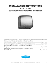
x 4
Ø 5/16" 8mm
1. 2. 3.
Ø7/8" 22mm
Foro per far passare il cavo nel muro
Flangia inseribile per
il montaggio sulla superficie
9-1/4" 235mm
7-3/4" 197mm
13-25/32" 350mm
13-19/32" 345mm
Ø7/8" 22mm
Foro per far passare il cavo nel muro
Form No. 712-69 Multi Language (Rev. 2/19/18) © 2018 Bobrick Washroom Equipment, Inc.
Caratteristiche Elettriche
Altezze di montaggio raccomandate
Rimozione della Copertura
Installazione della Base di montaggio
ATTENZIONE: SCOLLEGARE LA CORRENTE ELETTRICA PRIMA
DI REALIZZARE CONNESSIONI ELETTRICHE. IL DISPOSITIVO
ASCIUGAMANI DEVE ESSERE MESSO A MASSA (MESSO A TERRA).
Importante
10
1. Iniziare ad installare il dispositivo
asciugamani rimuovendo il
rivestimento. Rimuovere due viti
dalla parte inferiore del dispositivo
asciugamani.
Sfilare il rivestimento dallabase
di montaggio.
Distanza dal pavimento ai fori delle viti di fissaggio inferiori della base di montaggio.
Dispositivi asciugamani per bagni di bambini di 3-4 anni .........................................................................................................36'' (915mm)
Dispositivi asciugamani per bagni di bambini di 5-8 anni .........................................................................................................40'' (1.015mm)
Dispositivi asciugamani per bagni di bambini di 9-12 anni .......................................................................................................44'' (1.120mm)
Design universale .....................................................................................................................................................................48'' (1.219mm)
1. Collocare la dima di installazione contro la parete nella posizione desiderata in
cui si vuole installare il dispositivo asciugamani. Fare riferimento alle altezze di
montaggio consigliate sopra.
2. Assicurarsi che la linea sulla dima che rappresenta la parte inferiore della
base di montaggio del dispositivo asciugamani sia orizzontale e posizionata
all'altezza desiderata rispetto al pavimento.
3. Centrare i quattro fori delle viti di montaggio per inserire il cablaggio elettrico se
l'alimentazione elettrica è inserita nella parete e entra nel dispositivo dal retro,
attraverso la base di montaggio.
NOTA: l'entrata per l'alimentazione posta in superficie è collocata nell'angolo
inferiore destro della base di montaggio. Il cavo di allimentazione deve essere
inserito in una canalina.
4. Per pareti in mattone, pietra e cemento, eseguire con il trapano quattro fori da 8
mm (0.315") per posizionare al muro tasselli da 8 mm x
45 mm (1-1/4") e viti da 4.8 mm (10) x 50 mm (2") di lunghezza (fornite). Per i
particolari sull'installazione dei tasselli e delle viti a muso, fare riferimento alla
dima.
5. Per pareti di gesso o a secco, fornire un sostegno nascosto per per ottemperare
alla normativa edile locale e fissare con quattro viti da lamiera a testa tonda N°
10 (M4.8) o bulloni ad alette da 5 mm (3/16'') (non forniti).
6. Fissare la base di montaggio alla parete.
* I dispositivi asciuco 380 mm (15") al di sopra di qualsiasi superficie sporgente o orizzontale che possa interferire con il funzionamento del sensore
automatico.
Modello B-7120 Rivestimento bianco in acciaio inossidabile verniciato e B-7128 Rivestimento in acciaio inossidabile, 115 V ca., 15 Amp,
1725 Watt, 50/60 Hz, monofase, omologato cULus.
Modello B-7120 Rivestimento bianco in acciaio inossidabile verniciato e Modello B-7128 con rivestimento in acciaio inossidabile, 208–240V
ca., 6.8-7.8 Amp, 1400-1900 Watts, 50/60 Hz, monofase, omologato cULus, approvato da VDE e contrassegnato con marchio CE.
Le istruzioni per l'installazione e la dima contengono informazioni che aiutano per l'installazione del modello B-7120 e B-7128 115V, B-7120 e B-7128
208-240V della Bobrick. Conservate il libretto contenente le istruzioni per l'installazione perchè riportano importanti istruzioni di manutenzione e
informazioni sulla garanzia.
* Asciugamani ad aria calda. Ideale per l'uso in ambiente domestico da utenti non esperti. Non è indicato per l'uso all'aperto.
** Questo apparecchio può essere utilizzato da bambini dagli 8 anni in su e da persone che presentano ridotte capacità fisiche,
sensoriali o mentali o che difettano della necessaria esperienza e/o conoscenza, purché siano adeguatamente sorvegliati o addestrati
sull'uso dell'apparecchio in sicurezza e siano a conoscenza dei rischi correlati. I bambini non devono giocare con l'apparecchio, e
non possono pulirlo o effettuarne la manutenzione senza un'adeguata sorveglianza.
*** In caso di guasto, staccare la presa di corrente e rivolgersi a un elettricista qualificato.
L'INSTALLAZIONE DEVE ESSERE DIRETTA DA UN ELETTRICISTA
QUALIFICATO.

Form No. 712-69 Multi Language (Rev. 2/19/18) © 2018 Bobrick Washroom Equipment, Inc.
Collegamento elettrico
Verificare l'operatività del dispositivo asciuga
Manutenzione
Sostituire il rivestimento
11
1. Collegate l'energia elettrica.
2. Mettere le mani sotto il bocchettone d'aria, a 100 mm (4'') dalla parte inferiore del dispositivo asciugamani.
3. Il dispositivo asciugamani deve avviarsi. Deve uscire aria calda dal bocchettone dell'aria. Il tempo di
asciugatura dura meno di 25 secondi.
4. Togliendo le mani da sotto il bocchettone dell'aria il dispositivo asciugamani deve fermarsi (entro 2 secondi).
1. Collocare il rivestimento sulla base
di montaggio.
NOTA: I quattro lati della copertura
si sovrappongono alla base di
montaggio e devono essere allineati
con i lati, la parte superiore ed
inferiore della base di montaggio.
2. Ricollocare e stringere due viti,
sulla parte inferiore per fissare
il rivestimento alla base di
montaggio.
PER ESEGUIRE CORRETTAMENTE I COLLEGAMENTI ELETTRICI, VERIFICARE LE NORMATIVE LOCALI SULLE COSTRUZIONI.
L’APPARECCHIO DEVE ESSERE INSTALLATO DA UN ELETTRICISTA AUTORIZZATO QUALIFICATO.
1. Collegare l’asciugamano al quadro di distribuzione più vicino. Usare il filo come richiesto dalle normative elettriche locali. Negli Stati Uniti e in
Canada usare un cavo #12 o maggiore.
2. Istruzioni per il cablaggio:
a. Questo apparecchio deve essere collegato a un cablaggio fisso.
b. Ai fini della disconnessione di tutti i terminali, l’impianto elettrico fisso deve essere munito di un dispositivo con fusibile conforme alle norme
elettriche vigenti.
c. Verificare che la potenza elettrica nominale riportata sull'asciugamani (targhetta energetica) sia compatibile con l'alimentazione elettrica.
d. AVVERTENZA: QUESTO PRODOTTO DEVE ESSERE MESSO A TERRA.
e. L'installazione e il cablaggio devono essere conformi alle direttive IEE (nel Regno Unito), locali o pertinenti (in altri paesi) in vigore.
f. Per gli asciugamani da 115 Volt: Collegare la presa di terra (massa) al morsetto contrassegnato , il conduttore sotto tensione al morsetto
contrassegnato (L) e il cavo neutro al morsetto contrassegnato (N). N. PER CIASCUN ASCIUGAMANO DA 115 VOLT È NECESSARIA UNA
LINEA DEDICATA.
g. Per gli asciugamani da 208-240 Volt: Collegare la presa di terra (massa) al morsetto contrassegnato , il conduttore sotto tensione al
morsetto contrassegnato (L) e il cavo neutro al morsetto contrassegnato (N).
3. Fissare il cavo elettrico nel morsetto di protezione fornito sulla base di montaggio.
AVVERTENZA: IL LAMIERINO MAGNETICO È SOTTO TENSIONE. METTERE FUORI SERVIZIO L’ALIMENTAZIONE ELETTRICA PRIMA DI
ESEGUIRE QUALSIASI OPERAZIONE DI MANUTENZIONE O ASSISTENZA SULL’ASCIUGAMANO. L’ASCIUGAMANO NON DEVE ESSERE
ATTIVATO SE LA CARCASSA NON SI TROVA IN POSIZIONE.
L'INSTALLAZIONE DEVE ESSERE DIRETTA DA UN ELETTRICISTA QUALIFICATO.
1. Pulire la superficie esterna della carcassa con un panno umido per rimuovere la polvere e lo sporco superficiale. Non usare agenti abrasivi o
solventi, in quanto potrebbero danneggiare la superficie della carcassa in modo permanente.
2. La carcassa va rimossa almeno una volta ogni 6 mesi. Servendosi di una spazzolina o di un aspirapolvere, pulire l’accumulo di polvere e
lanugine dalla griglia della presa dell’aria e dal diaframma.
NOTA : Se l’asciugamano è installato in un luogo dove c’è molta polvere e sporco nell’aria, è necessario pulire più spesso l’interno dell’asciugamano.

x 4
Ø 5/16" 8mm
1. 2. 3.
Ø7/8" 22mm
Hole for between wall wiring
Flange cutout for
surface mounting
9-1/4" 235mm
7-3/4" 197mm
13-25/32" 350mm
13-19/32" 345mm
Ø7/8" 22mm
Hole for between wall wiring
Form No. 712-69 Multi Language (Rev. 2/19/18) © 2018 Bobrick Washroom Equipment, Inc.
安装基座
取下外罩
重要事项
电气特征
12
建议安装高度
1. 将安装基座固定到您想要的安装位置,参见上面的建议安装高度。
2. 确认安装基座的安装线与底座末端处于同一水平线,并且符合安装高
度的要求。
3. 标出四个安装孔的中点位置及电源线接入孔位置;电源线如果是隐藏在
墙内
的需从干手机的背面穿过基座。
注意: 电源线若是在墙面排设的明线,可从右下部与安装基座连接。安
装基座上
的凸缘和外罩底部在右下角有一豁口,便于接入导入管。
4. 如果是砖块、石头、钢筋混泥土,在墙上钻四个8mm孔,供8mm*45mm的
螺栓
和4.8mm*50mm的螺栓使用,详见模板有关螺钉的安装细节。
5. 针对石灰水泥,则在墙上钻四个供6.4mm直径的螺栓或螺钉的孔位
(Bobrick公司不随机配附)。
6. 将安装基座牢牢地固定在墙上。警告:进行电气安装接线操作之前必须
切断电源,吹干器必须接地。
B-7120型 白色喷粉不锈钢外壳 、B-7128型 不锈钢外壳, 115伏 交流, 15安培, 1725 瓦, 50/60 赫兹单相电机,获有cULus 认证。
B-7120型 白色喷粉不锈钢外壳 、B-7128型 不锈钢外壳, 208–240伏 交流, 6.8-7.8安培, 1400-1900瓦, 50/60赫兹单相电机;获有cULus、 VDE
、 并带有CE 标志。
安装说明请见B-7120,B-7128 115伏以及B-7120,B-7128说明书;请妥善保存保养细则和授权信息。
从地面到安装基座上最底部安装螺孔的距离
3岁到4岁儿童洗手间 36″(915mm)
5岁到8岁儿童洗手间 40″(1015mm)
9岁到12岁儿童洗手间 44″(1120mm)
通用设计 48″(1219mm)
* Bobrick 自动干手机应安装在距离可能会影响自动传感器正常工作的凸出物体或水平表面上方380毫米处。
1. 安装干手机时,需取下外
壳,将随机附送的六角扳
手,插入进气格栅两侧底部
的螺栓孔内,松开固外罩的
两根螺栓罩。.
警告:开电源时需要确保电源线连接无误
吹干器必须节电。
2. 从外罩底部将其旋离底座,
并向上掀起外罩。
暖风干手机。供家居环境中非专业用户使用。不适合户外使用。
8 岁及以上儿童,以及生理、感官或心智能力下降或者缺乏相关经验及知识的人士,在有他人照顾或向其说明安全使用方式且理解相关
危险的情况下,可以使用本电器。儿童不可玩弄该设备。在未得到监护的情况下,儿童不得清洁或维修本电器。
若电器发生故障导致电源断开,应致电专业电工
必须在专业电工的监督下进行安装。

Form No. 712-69 Multi Language (Rev. 2/19/18) © 2018 Bobrick Washroom Equipment, Inc.
保养
检查吹干机的运转状况
装回外罩
电气接线
13
1 将外壳扣在底座上
注意:外壳四周必须平行底
座,底部
和顶部完全装配好。
2. 重新拧紧外壳螺丝
1、 打开电源;
2、 将手放置在距离干手机下方100mm的出风口处,干手机即会启动;
3、 从出风口处吹出暖风,干手时间小于25秒;
4、 当手离开出风口后,干手机应会停止运转(2秒内)。
为保证电路联接正确,请检查核对当地建筑部门法规。设备必须由合格的电工进行安装。
1.从附近的配电板上引出连接吹干器的电线。所用电线须符合当地电力部门的法规要求。在美国和加拿大,须用12号或更大号的电线。
2. 接线说明:
a. 本电器应连接至固定线路。
b. 必须按照接线规定在固定配线中设有能断开所有电极的带熔丝的装置。
c. 检查干手机(能效标签)上显示的额定电功率及电压与电源是否兼容。
d. 警告: 该产品必须接地。
e. 安装及布线必须遵照当前 IEE 布线规则(英国)以及其他国家/地区的地方或相应法规。
f. 针对115伏吹干器: 将地线与标记有 的接线端子相连接,将火线与标记有 (L) 的接线端子相连接,将零线与标记有
(N) 的接线端子相连接。 每台115伏吹干器均要求使用专用电线。
g. 针对208-240伏吹干器: 将地线与标记有 的接线端子相连接,将火线与标记有 (L) 的接线端子相连接,将零线与标
记有 (N) 的接线端子相连接。
3. 将电线牢牢固定在安装基座上提供的张力释放夹上。
警告:电机定转子铁心圆片是带电的。在对机器进行保养或技术服务之前,请务必关掉电源。在没有装回外罩之前,绝不可以操作机
器。
必须在专业电工的监督下进行安装。
1. 如需除去表面的灰尘,应当用潮湿的软布清洁机器外罩。请勿使用研磨剂或溶剂进行清洁,否则可能对吹干器的外罩造成永久性损
坏。
2. 至少每 6 个月取下外罩一次,用小刷子或吸尘器从进风口格栅清理出积尘和灰屑。
注意:如果吹干器安装在灰尘较多的环境中,则须更经常地进行机器内部的清洁。

Form No. 712-69 Multi Language (Rev. 2/19/18) © 2018 Bobrick Washroom Equipment, Inc.
Garantie
Garantía
Warranty
14
IMPORTANT LIMITED WARRANTY SAVE
Installation Date: _____________________________________________________________________________________________________________
Serial No(s).: _________________________________________________________________________________________________________________
Installation Address:___________________________________________________________________________________________________________
Telephone No.: _______________________________________________________________________________________________________________
The Bobrick B-7120 and B-7128 Dryer of the serial number(s) indicated herein, and all parts are warranted to the original owner of the installed unit for ten years
from date of original purchase against defects in factory workmanship or material under normal use and service
*
.
This warranty is limited to repair or exchange of defective parts at the option of Bobrick.
THIS WARRANTY DOES NOT COVER ACCIDENTAL DAMAGE, IMPROPER HANDLING OR INSTALLATION, OR REPAIRS MADE BY UNAUTHORIZED
PER SONS, AND SPECIFICALLY EXCLUDES CLAIMS FOR INDIRECT, ACCI DENTAL OR CONSEQUENTIAL DAMAGES TO PROPERTY. THE IMPLIED
WARRANTIES OF MERCHANTABILITY AND FITNESS FOR A PARTICULAR PURPOSE ARE LIMITED TO THE SAME DURATION OF THE ABOVE WAR-
RANTY.
Some states do not allow the exclusion of incidental or consequential damages, so the above limitation or exclusion may not apply to you. Some states do not allow
limitations on how long an implied warranty lasts, so the above limitation may not apply to you. This warranty gives you specific legal rights, and you may also have
other rights which vary from state to state.
*
Normal service constitutes performing the following preventive maintenance procedure: Clean any lint, dust or grease from air-inlet and air-outlet grilles.
Labor costs for preventive maintenance shall be at owner's expense.
For repair or exchange of defective part, send the part together with installation date and serial number to BOBRICK.
IMPORTANTE GARANTÍA LIMITADA GUARDAR
Fecha de Instalación: __________________________________________________________________________________________________________
Números de Serie: ____________________________________________________________________________________________________________
Dirección de la Instalación: _____________________________________________________________________________________________________
N.º de Teléfono: _______________________________________________________________________________________________________________
El/Los secador/es Bobrick B-7120 y B-7128 EdgeSeries™ Dryer, con el/los número/s de serie indicado/s aquí y todas las piezas, tienen garantía para el propietario
original de compra, por diez años, contra los defectos de mano de obra en fábrica o de materiales, bajo uso y servicio normales
*
.
Esta garantía está limitada a la reparación o cambio de piezas defectuosas a la discreción de Bobrick.
ESTA GARANTÍA NO CUBRE DAÑOS ACCIDENTALES, EL MANEJO O LA INSTALACIÓN INADECUADOS NI LAS REPARACIONES EFECTUADAS POR
PERSONAS NO AUTORIZADAS, Y EXCLUYE ESPECÍFICAMENTE CUALQUIER RECLAMO POR DAÑOS INDIRECTOS, ACCIDENTALES O RESULTANTES
A LA PROPIEDAD. SE LIMITAN LAS GARANTÍAS IMPLÍCITAS DE COMERCIABILIDAD Y APTITUD PARA UN PROPÓSITO ESPECÍFICO A LA MISMA
DURACIÓN QUE LA SUSODICHA GARANTÍA.
Algunos estados no permiten la exclusión de daños incidentales o resultantes, así que la susodicha limitación o exclusión quizás no corresponda a su caso. Algunos
estados no permiten la limitación sobre la duración de la garantía implícita, así que la susodicha limitación quizás no corresponda a su caso. Esta garantía le otorga
ciertos derechos legales específicos, pero posiblemente usted tiene otros derechos que pueden variar entre estados.
*
El servicio normal consiste en realizar los siguientes procedimientos de mantenimiento preventivo: Eliminar todo tipo de fibra, polvo o grasa de la rejilla
de entrada/salida de aire.
Los gastos de mano de obra del mantenimiento preventivo correrán a cargo del propietario.
Para reparar o cambiar una pieza defectuosa, sírvase enviarla con su fecha de instalación y número de serie a BOBRICK.
WICHTIGER HINWEIS BESCHRÄNKTE HAFTUNG AUFBEWAHREN
Installationsdatum: ___________________________________________________________________________________________________________
Serien-Nummer(n): ____________________________________________________________________________________________________________
Installationsanschrift: __________________________________________________________________________________________________________
Telefon: _____________________________________________________________________________________________________________________
Der Bobrick B-7120 und B-7128 Trockner der Seriennummer (n) hier angezeigt, und alle Teile sind dem ursprünglichen Eigentümer der installierten Einheit für zehn Jahre ab
dem Datum des ursprünglichen Kaufs gegen Fabrikarbeitsausführungsfehler oder Materialschäden unter normalem Gebrauch und Dienst garantiert
*
.
Diese Garantie ist begrenzt auf Reparatur oder Austausch von mangelhaften Teilen auf Ermessen von Bobrick.
DIESE GARANTIE DECKT NICHT ZUFÄLLIGE SCHÄDEN, UNZULÄSSIGE HANDHABUNG ODER INSTALLATION, ODER REPARATUREN, DIE VON
UNBEFUGTEN PERSONEN GEMACHT WURDEN "ab", UND SCHLIESST AUSDRÜCKLICH ANSPRÜCHE FÜR, ZUFÄLLIGE ODER INDIREKTE SCHÄDEN AM
EIGENTUM AUS. DIE IMPLIZITEN GARANTIEN HINSICHTLICH DER MARKTGÄNGIGKEIT UND EIGNUNG FÜR EINEN BESONDEREN ZWECK SIND AUF DIE
GLEICHE DAUER DER OBEREN GARANTIE BEGRENZT.
Einige Staaten erlauben nicht die Ausschließung einhergehender oder indirekter Schäden, deshalb kann es sein, daß die obere Begrenzung oder die Ausschließung
für Sie nicht gelten. Einige Staaten erlauben keine Begrenzungen, hinsichtlich der Währung einer impliziten Garantie, deshalb kann die obere Begrenzung für Sie
nicht gelten. Diese Garantie gibt Ihnen spezifische gesetzliche Rechte, und Sie können auch andere Rechte haben, die von Staat zu Staat anders sind.
*
Bei normalem Betrieb müssen folgenden vorbeugende Wartungsverfahren durchgeführt werden: Jegliche Fussel, Staub oder Schmierfett vom
Lufteinlass- und Luftauslassgitter entfernen.
Arbeitskosten für vorbeugende Wartung gehen auf Kosten des Eigentümers.
Für Reparatur oder Umtausch mangelhafter Teile, den Artikel zusammen mit dem Installationdatum und der Seriennummer BOBRICK zuschicken.

Form No. 712-69 Multi Language (Rev. 2/19/18) © 2018 Bobrick Washroom Equipment, Inc.
保修卡
Garanzia
Garantie
15
IMPORTANT GARANTIE LIMITÉE À CONSERVER
Date d'installation : ___________________________________________________________________________________________________________
Nos de séries : _______________________________________________________________________________________________________________
Adresse de l'installation : _______________________________________________________________________________________________________
Téléphone : __________________________________________________________________________________________________________________
La présente garantie couvre toutes les pièces pour les numéros de série des modèles de sèche-mains B-7120 et B-7128 EdgeSeries
MC
de Bobrick indiqués dans
le présent document, et est dédiée au premier propriétaire de l'appareil installé, pour une période de dix ans, et ce, depuis la date origina le de l'achat contre tous
défauts de fabrication ou de matériaux pour l'utilisation normale et le respect des entretiens périodiques*.
Cette garantie est limitée à la réparation ou au remplacement des pièces défectueuses, au choix de Bobrick.
CETTE GARANTIE NE COUVRE PAS LES DOMMAGES ACCIDENTELS, L'UTILISATION OU L'INSTALLATION INADÉQUATE, OU LES RÉPARATIONS
DÉFECTUEUSES EFFECTUÉES PAR DES RÉPARATEURS NON AGRÉÉS, ET EXCLUT SPÉCIFIQUEMENT LES DOMMAGES INDIRECTS, ACCIDENTELS
OU IMMATÉRIELS À LA PROPRIÉTÉ. LES GARANTIES TACITES DE QUALITÉ MARCHANDE OU D'ADÉQUATION POUR UNE UTILISATION PARTICULIÈRE
SONT LIMITÉES À LA MÊME DURÉE DE LA GARANTIE CI-DESSUS.
Certaines provinces n'autorisent pas l'exclusion des dommages accessoires ou immatériels de sorte que cette clause ne s'applique peut-être pas à vous. Certaines
provinces n'autorisent pas les limitations de durée des garanties limitées de sorte que cette condition ne s'applique peut-être pas à vous. Cette garantie vous donne
des droits spécifiques ainsi que d'autres droits pouvant varier selon la province où vous habitez.
*
Un entretien normal consiste à effectuer la procédure d'entretien préventif suivante : Nettoyer toute peluche, poussière ou graisse des grilles
d'admission et de sortie d'air.
Le propriétaire doit assumer les coûts de l'entretien préventif.
Envoyer la pièce défectueuse pour la réparation ou le remplacement à BOBRICK en indiquant la date de l'installation et le numéro de série.
IMPORTANTE GARANZIA LIMITATA CONSERVARE
Data di installazione: __________________________________________________________________________________________________________
Numero di serie: ______________________________________________________________________________________________________________
Indirizzo di installazione: _______________________________________________________________________________________________________
Numero di telefono: ___________________________________________________________________________________________________________
Il dispositivo asciugamani, modello B-7120 e B-7128 della Bobrick, con numero/i di matricola indicato/i in questa sezione, e i relativi componenti sono coperti dalla
garanzia del primo proprietario dell'unità installata. La garanzia ha una validità di dieci anni dalla data d'acquisto e si riferisce a difetti di fabbrica o materiali che
vengono usati normalmente
*
.
Questa garanzia si limita a riparare o sostituire le parti difettose, a discrezione della Bobrick.
QUESTA GARANZIA NON COPRE DANNI ACCIDENTALI, MOVIMENTAZIONE O INSTALLAZIONE IMPROPRIE O RIPARAZIONI ESEGUITE DA PERSONE
NON AUTORIZZATE, ED ESCLUDE SPECIFICATAMENTE RECLAMI PER DANNI INDIRETTI, INCIDENTALI O CONSEGUENTI AI BENI. LE GARANZIE
TACITE DELLA COMMERCIABILITA' E DELL'ADEGUATEZZA PER UNO SCOPO PARTICOLARE HANNO LA STESSA DURATA DELLA GARANZIA
SUMMENZIONATA.
Alcuni stati non permettono l'esclusione di danni accidentali o conseguenti, così la summenzionata limitazione od esclusione può non essere valida per il cliente.
Alcuni stati non permettono limitazioni sulla durata della tacita garanzia, così la summenzionata limitazione od esclusione può non essere valida per il cliente.
Questa garanzia conferisce diritti legali specifici al cliente il quale può anche averne altri che variano da paese a paese.
*
I normali interventi di manutenzione prevedono la seguente procedura preventiva: Pulire da lanugine, polvere o grasso le griglie dei bocchettoni di
entrata ed uscita dell'aria.
I costi di manodopera per la manutenzione preventiva sono a carico del proprietario.
Per la riparazione o la sostituzione di parti difettose, inviare il componente indicando la data di installazione e il numero di matricola alla BOBRICK.
重要文件 _________________________________________________________________________________________________________________________ 保修
范围 _____________________________________________________________________________________________________________________________ 注意
保存
安装日期: _______________________________________________________________________________________________________________________
系列号: __________________________________________________________________________________________________________________________
安装地址: ________________________________________________________________________________________________________________________
电话号码: ________________________________________________________________________________________________________________________
这里所填系列号所指的 Bobrick吹干器B-7120 和 B-7128及其全部部件均在保修范围内,本设备的最初拥有者享有十年的保修期,在正常使用和维修时因
原厂制造工艺或使用材料所引起的问题均在保修范围内。
此项保修仅限于修理或更换Bobrick卫浴设施有限公司认为质量问题的零部件。
以下情况不属保修范围:事故性损坏、不正确的使用或安装、非授权人员维修造成的损坏,特别是间接引起的、事故性的或后果性的财产损失均不在保修
范围之内。
可销售性和具体用途的适用性所隐含的保修范围和保修时间同上。
有些州不允许将偶然性或后果性损坏排除在保修范围之外,因此上述保修范围及限制对您可能有不适用之处。有些州不允许对隐含的保修期作出限制,因
此上述保修限制亦可能有不适用之处。此保修卡已给了您详细而明确的法定权益,您也可能因各州不同的法规而获有其他权益。
*常规技术服务由预防性维护组成: 清理进风口格栅或后部出风口处的灰尘或油垢。
预防性维护的人工费由干手机拥有者支付。
如有需要修理或更换有质量问题的部件,请将该部件连同安装日期和系列号一起寄往 BOBRICK公司。

Form No. 712-69 Multi Language (Rev. 2/19/18) © 2018 Bobrick Washroom Equipment, Inc.
16
In the United States: BOBRICK WASHROOM EQUIPMENT, INC.
200 Commerce Drive, Clifton Park, NY 12065-1350, Telephone: (518) 877-7444 • FAX: 518-877-5029
6901 Tujunga Ave., North Hollywood, CA 91605-6213: (818) 982-9070 • FAX: 818-503-9287
or email customerservice@bobrick.com
In Canada: BOBRICK WASHROOM EQUIPMENT COMPANY
45 Rolark Drive, Scarborough, Ontario M1R 3B1 • FAX: (877) 423-8555
International:
BOBRICK WASHROOM EQUIPMENT, INC. 11611 Hart Street, North Hollywood, CA 91605-5882: (818) 764-1000, FAX: 818-503-9941
BOBRICK WASHROOM EQUIPMENT Pty, Ltd. Australia +1 (818) 764-1000, FAX: +1 (818) 503-9941
BOBRICK WASHROOM EQUIPMENT Limited United Kingdom +44 (0)20 8366 1771, FAX: +44 (0)20 8363 5794
-
 1
1
-
 2
2
-
 3
3
-
 4
4
-
 5
5
-
 6
6
-
 7
7
-
 8
8
-
 9
9
-
 10
10
-
 11
11
-
 12
12
-
 13
13
-
 14
14
-
 15
15
-
 16
16


in altre lingue
- français: Bobrick B-7120 Mode d'emploi
- español: Bobrick B-7120 Instrucciones de operación
- Deutsch: Bobrick B-7120 Bedienungsanleitung
Documenti correlati
-
 Bobrick B-770 115V Istruzioni per l'uso
-
Bobrick B-7179 Guida d'installazione
-
 Bobrick B-7125 InstaDry Installation Instructions Manual
-
 Bobrick B-710 Guida d'installazione
-
Bobrick B-750 115V Istruzioni per l'uso
-
 Bobrick B-715 Guida d'installazione
-
 Bobrick B-7180 115v Istruzioni per l'uso
-
 Bobrick B-7125 InstaDry Guida d'installazione


