
PART. U2068B
Istruzioni d’uso
Gebrauchanweisungen
Notice d’emploi
Instructions for use
Instrucciones de uso
Gebruiksaanwijzing
Istruçoes para o uso
09/15-01 PCF429
1
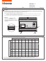
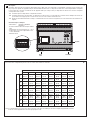
Descrizione
L’interfaccia SCS DALI art. F429 permette l’interfacciamento tra il BUS SCS e i dispositivi pilotabili con il protocollo DALI, in modo da poter
regolare dal BUS SCS gli apparecchi DALI. Il dispositivo ha 8 uscite indipendenti alle quali si possono collegare fino a 16 apparecchi DALI
per ogni uscita. Questo prodotto è dotato di tre tasti ai quali corrispondono tre led.
- P1 Consente di mettere il dispositivo in configurazione virtuale.
- P2 Permette di selezionare l’uscita DALI; premendolo il led lampeggerà un numero di volte pari al numero della porta selezionata.
Premendolo nuovamente selezioniamo l’uscita successiva.
- P3 Accende o spegne ciclicamente il carico; tenendolo premuto a lungo dimmerizza l’uscita che è stata selezionata con il P2.
I
OUTPUT
1 2 3 4 5 6 7 8
A=
1
A=1
PL=1
A=1
PL=2
A=1
PL=3
A=1
PL=4
A=1
PL=5
A=1
PL=6
A=1
PL=7
A=1
PL=8
2
A=2
PL=1
A=2
PL=2
A=2
PL=3
A=2
PL=4
A=2
PL=5
A=2
PL=6
A=2
PL=7
A=2
PL=8
3
A=3
PL=1
A=3
PL=2
A=3
PL=3
A=3
PL=4
A=3
PL=5
A=3
PL=6
A=3
PL=7
A=3
PL=8
4
A=4
PL=1
A=4
PL=2
A=4
PL=3
A=4
PL=4
A=4
PL=5
A=4
PL=6
A=4
PL=7
A=4
PL=8
5
A=5
PL=1
A=5
PL=2
A=5
PL=3
A=5
PL=4
A=5
PL=5
A=5
PL=6
A=5
PL=7
A=5
PL=8
6
A=6
PL=1
A=6
PL=2
A=6
PL=3
A=6
PL=4
A=6
PL=5
A=6
PL=6
A=6
PL=7
A=6
PL=8
7
A=7
PL=1
A=7
PL=2
A=7
PL=3
A=7
PL=4
A=7
PL=5
A=7
PL=6
A=7
PL=7
A=7
PL=8
8
A=8
PL=1
A=8
PL=2
A=8
PL=3
A=8
PL=4
A=8
PL=5
A=8
PL=6
A=8
PL=7
A=8
PL=8
9
A=9
PL=1
A=9
PL=2
A=9
PL=3
A=9
PL=4
A=9
PL=5
A=9
PL=6
A=9
PL=7
A=9
PL=8
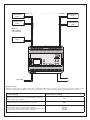
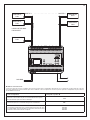
Dati tecnici
• Alimentazione: 110-240V AC 50/60HZ
110-240V DC
• Corrente massima assorbita: 5mA dal BUS SCS
• Temperatura di funzionamento: 5°C ÷ 45°C
• Uscite DALI: 8 indipendenti secondo IEC 62386
• Moduli DIN: 6
L
N
8
7
6
5
_
+
_
+
_
+
_
+
4
3
2
1
_
+
_
+
_
+
_
+
OUTPUT
BUS
SCS
110-240V
Led
A G M
2
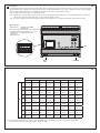
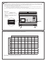
In funzione del configuratore inserito in A le uscite assumono il seguente indirizzo:
N.B. Non è previsto il configuratore PL, in quanto il valore è stabilito dall’uscita a cui è collegato l’apparecchio DALI
Tutte le uscite appartengono allo stesso gruppo inserito in G.

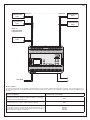
3
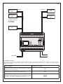
Schema di collegamento
MAX 16
DISPOSITIVI
PER USCITA
DISPOSITIVO
DALI
BUS DALI
L
N
BUS SCS
USCITA 1 - - - - - - - - - - - - - USCITA 8
DISPOSITIVO
DALI
DISPOSITIVO
DALI
DISPOSITIVO
DALI
DISPOSITIVO
DALI
- - - -
L
N
8
7
6
5
_
+
_
+
_
+
_
+
4
3
2
1
_
+
_
+
_
+
_
+
OUTPUT
Modalità operative
L’attuatore esegue tutte le modalità operative base configurabili direttamente sul comando, escluse quelle che prevedono l’utilizzo di relè
interbloccanti. Nella seguente tabella si elencano le funzioni previste con il configuratore inserito nella posizione M dello stesso attuatore.
Funzioni realizzabili Configurazione posizione M
Attuatore come Slave. Riceve un comando inviato da un attuatore
master che ha lo stesso indirizzo.
SLA
L’attuatore ignora i comandi di tipo Ambiente e Generale.
PUL
Attuatore Master con comando di OFF ritardato sul corrispondente
attuatore Slave. Solo per comando di tipo punto-punto.
Con il comando di OFF l’attuatore Master si disattiva; l’attuatore Slave
si disattiva dopo che è trascorso il tempo configurato.
1=1 min
2=2 min
3=3 min
4=4 min

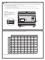
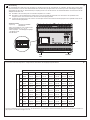
Description
The SCS DALI interface item F429 allows interfacing between the SCS BUS and the devices which can be driven with the DALI protocol,
so that the DALI devices can be adjusted from the SCS BUS. The device has 8 independent outputs to which up to 16 DALI devices can
be connected for each output. This product has three keys with three LED.
- P1 Puts the device in virtual configuration.
- P2 Selects the DALI output; pressing the LED will flash a number of times equal to the number of the port selected.
Pressing it again we select the next output.
- P3 Switches the load on or off cyclically; keeping it pressed for a long time dims the output which has been selected with the P2.
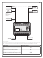
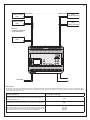
Technical data
• Power supply: 110-240V AC 50/60HZ
110-240V DC
• Maximum input power: 5MA from the SCS BUS
• Operating temperature: 5°C ÷ 45°C
• DALI outputs: 8independent according to:
IEC 62386
• DIN modules: 6
OUTPUT
1 2 3 4 5 6 7 8
A=
1
A=1
PL=1
A=1
PL=2
A=1
PL=3
A=1
PL=4
A=1
PL=5
A=1
PL=6
A=1
PL=7
A=1
PL=8
2
A=2
PL=1
A=2
PL=2
A=2
PL=3
A=2
PL=4
A=2
PL=5
A=2
PL=6
A=2
PL=7
A=2
PL=8
3
A=3
PL=1
A=3
PL=2
A=3
PL=3
A=3
PL=4
A=3
PL=5
A=3
PL=6
A=3
PL=7
A=3
PL=8
4
A=4
PL=1
A=4
PL=2
A=4
PL=3
A=4
PL=4
A=4
PL=5
A=4
PL=6
A=4
PL=7
A=4
PL=8
5
A=5
PL=1
A=5
PL=2
A=5
PL=3
A=5
PL=4
A=5
PL=5
A=5
PL=6
A=5
PL=7
A=5
PL=8
6
A=6
PL=1
A=6
PL=2
A=6
PL=3
A=6
PL=4
A=6
PL=5
A=6
PL=6
A=6
PL=7
A=6
PL=8
7
A=7
PL=1
A=7
PL=2
A=7
PL=3
A=7
PL=4
A=7
PL=5
A=7
PL=6
A=7
PL=7
A=7
PL=8
8
A=8
PL=1
A=8
PL=2
A=8
PL=3
A=8
PL=4
A=8
PL=5
A=8
PL=6
A=8
PL=7
A=8
PL=8
9
A=9
PL=1
A=9
PL=2
A=9
PL=3
A=9
PL=4
A=9
PL=5
A=9
PL=6
A=9
PL=7
A=9
PL=8
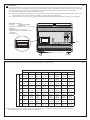
Depending on the configurator inserted in A the outputs assume the following address:
N.B. The PL configurator is not present, because the value is set by the output to which the DALI device is connected.
All the outputs belong to the same group entered in G.
GB
10
11
BUS
SCS
110-240V
Led
L
N
8
7
6
5
_
+
_
+
_
+
_
+
4
3
2
1
_
+
_
+
_
+
_
+
OUTPUT
A G M

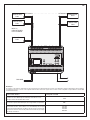
MAX 16
DEVICES FOR
OUTPUT
DALI
DEVICE
DALI BUS
L
N
SCS BUS
OUTPUT 1 - - - - - - - - - - - - - OUTPUT 8
DALI
DEVICE
DALI
DEVICE
DALI
DEVICE
DALI
DEVICE
- - - -
L
N
8
7
6
5
_
+
_
+
_
+
_
+
4
3
2
1
_
+
_
+
_
+
_
+
OUTPUT
12
Wiring diagram
Modes of operation
The actuator performs all the basic modes of operation which can be configured directly on the control, apart from those which use interlocking
relays. The following table lists the functions which can be performed with the configurator inserted in position M of the same actuator.
Possible functions Configurator position M
Actuator as Slave. Receives a command sent from a master actuator
with the same address.
SLA
The actuator ignores the Room and General commands.
PUL
Master Actuator with OFF command delayed on the corresponding
slave actuator. Only for point-point command.
With the OFF command the Master actuator deactivates: the Slave ac-
tuator deactivates after the configured time has elapsed.
1=1 min
2=2 min
3=3 min
4=4 min

Description
L’interface SCS DALI réf. F429 permet l’interfaçage entre le BUS SCS et les dispositifs commandables à l’aide du protocole DALI, de
façon à pouvoir réguler les appareils DALI par l’intermédiaire du BUS SCS. Le dispositif est doté de 8 sorties indépendantes auxquelles
il est possible de connecter un maximum de 16 appareils DALI (sur chaque sortie). Le dispositif est doté de trois touches auxquelles
correspondent trois voyants.
- P1 Permet de placer le dispositif en configuration virtuelle.
- P2 Permet de sélectionner la sortie DALI ; en appuyant sur cette touche, le voyant clignote un nombre de fois identique au numéro du
port sélectionné. En appuyant à nouveau sur la touche, la sortie suivante est sélectionnée.
- P3 Allume et éteint alternativement la charge ; en maintenant la touche enfoncée longuement, la sortie sélectionnée à l’aide de P2 est
régulée.
Caractéristiques techniques
• Alimentation: 110-240Vca 50/60HZ
110-240Vcc
• Courant maximum absorbé: 5mA par le BUS
SCS
• Température de fonctionnement: 5°C ÷ 45°C
• Sorties DALI: 8 isorties indépendantes aux
normes IEC 62386
• Modules DIN: 6
SORTIE
1 2 3 4 5 6 7 8
A=
1
A=1
PL=1
A=1
PL=2
A=1
PL=3
A=1
PL=4
A=1
PL=5
A=1
PL=6
A=1
PL=7
A=1
PL=8
2
A=2
PL=1
A=2
PL=2
A=2
PL=3
A=2
PL=4
A=2
PL=5
A=2
PL=6
A=2
PL=7
A=2
PL=8
3
A=3
PL=1
A=3
PL=2
A=3
PL=3
A=3
PL=4
A=3
PL=5
A=3
PL=6
A=3
PL=7
A=3
PL=8
4
A=4
PL=1
A=4
PL=2
A=4
PL=3
A=4
PL=4
A=4
PL=5
A=4
PL=6
A=4
PL=7
A=4
PL=8
5
A=5
PL=1
A=5
PL=2
A=5
PL=3
A=5
PL=4
A=5
PL=5
A=5
PL=6
A=5
PL=7
A=5
PL=8
6
A=6
PL=1
A=6
PL=2
A=6
PL=3
A=6
PL=4
A=6
PL=5
A=6
PL=6
A=6
PL=7
A=6
PL=8
7
A=7
PL=1
A=7
PL=2
A=7
PL=3
A=7
PL=4
A=7
PL=5
A=7
PL=6
A=7
PL=7
A=7
PL=8
8
A=8
PL=1
A=8
PL=2
A=8
PL=3
A=8
PL=4
A=8
PL=5
A=8
PL=6
A=8
PL=7
A=8
PL=8
9
A=9
PL=1
A=9
PL=2
A=9
PL=3
A=9
PL=4
A=9
PL=5
A=9
PL=6
A=9
PL=7
A=9
PL=8
En fonction des configurateurs placés en A, les sorties ont les adresses suivantes:
N.B. Le configurateur PL n’est pas prévu dans la mesure où la valeur est établie par la sortie à laquelle l’appareil DALI est relié.
Toutes les sorties appartiennent au même groupe placé en G.
F
7
8
BUS
SCS
110-240V
Voyant
L
N
8
7
6
5
_
+
_
+
_
+
_
+
4
3
2
1
_
+
_
+
_
+
_
+
OUTPUT
A G M

9
Schéma de branchement
6 DISPOSITIFS MAX.
PAR SORTIE
DISPOSITIF
DALI
BUS DALI
L
N
SCS BUS
SORTIE 1 - - - - - - - - - - - - - SORTIE 8
DISPOSITIF
DALI
DISPOSITIF
DALI
DISPOSITIF
DALI
DISPOSITIF
DALI
- - - -
L
N
8
7
6
5
_
+
_
+
_
+
_
+
4
3
2
1
_
+
_
+
_
+
_
+
OUTPUT
Modalité de fonctionnement
L’actionneur exécute toutes les modalités de fonctionnement de base configurables directement sur la commande, exception faite de celles qui
prévoient l’utilisation de relais à interblocage. Dans le tableau ci-dessous figurent les fonctions prévues quand le configurateur est placé dans la
position M de l’actionneur.
Fonctions disponibles Configuration position M
Actionneur comme Slave. Reçoit une commande transmise par un
actionneur Master ayant une adresse identique.
SLA
L’actionneur ignore les commandes de type Pièce et Général.
PUL
Actionneur Master à commande OFF retardée sur l’actionneur Slave
correspondant. Uniquement pour commande de type point-point. Avec
la commande OFF, l’actionneur Master se désactive; l’actionneur Slave
se désactive au bout de la durée configurée.
1=1 min
2=2 min
3=3 min
4=4 min

4
Beschreibung
Die Schnittstelle SCS DALI Art. F429 ermöglicht es den BUS SCS mit den Vorrichtungen zu verbinden, die über das Protokoll DALI
gesteuert werden. So können dann die DALI Geräte über den BUS SCS geregelt werden. Die Vorrichtung ist mit 8 unabhängigen Ausgängen
ausgestattet an denen bis zu 16 DALI Geräte pro Ausgang geschlossen werden können. An dem Gerät befinden sich drei Tasten mit den
dazugehörenden drei Leds.
- P1 Gestattet es die Vorrichtung auf eine virtuelle Konfiguration zu schalten.
- P2 Ermöglicht es den Ausgang DALI zu wählen. Nach einem Druck blinkt die Led X-Mal, was der Nummer des gewählten Ports
entspricht. Durch einen erneuten Druck, wird der nächste Ausgang gewählt.
- P3 Schaltet die Stromlast zyklisch ein und aus. Durch längeres Drücken der Taste wird der Ausgang der mit P2 gewählt wurde, auf die
Dimmerschaltung eingestellt
Technische Daten
• Speisung: 110-240V AC 50/60HZ
110-240V DC
• Max. Stromaufnahme: 5mA vom BUS SCS
• Betriebstemperatur: 5°C ÷ 45°C
• DALI Ausgänge: 8 unabhängige Ausgänge
gemäß IEC 62386
• DIN Module: 6
5
AUSGANG
1 2 3 4 5 6 7 8
A=
1
A=1
PL=1
A=1
PL=2
A=1
PL=3
A=1
PL=4
A=1
PL=5
A=1
PL=6
A=1
PL=7
A=1
PL=8
2
A=2
PL=1
A=2
PL=2
A=2
PL=3
A=2
PL=4
A=2
PL=5
A=2
PL=6
A=2
PL=7
A=2
PL=8
3
A=3
PL=1
A=3
PL=2
A=3
PL=3
A=3
PL=4
A=3
PL=5
A=3
PL=6
A=3
PL=7
A=3
PL=8
4
A=4
PL=1
A=4
PL=2
A=4
PL=3
A=4
PL=4
A=4
PL=5
A=4
PL=6
A=4
PL=7
A=4
PL=8
5
A=5
PL=1
A=5
PL=2
A=5
PL=3
A=5
PL=4
A=5
PL=5
A=5
PL=6
A=5
PL=7
A=5
PL=8
6
A=6
PL=1
A=6
PL=2
A=6
PL=3
A=6
PL=4
A=6
PL=5
A=6
PL=6
A=6
PL=7
A=6
PL=8
7
A=7
PL=1
A=7
PL=2
A=7
PL=3
A=7
PL=4
A=7
PL=5
A=7
PL=6
A=7
PL=7
A=7
PL=8
8
A=8
PL=1
A=8
PL=2
A=8
PL=3
A=8
PL=4
A=8
PL=5
A=8
PL=6
A=8
PL=7
A=8
PL=8
9
A=9
PL=1
A=9
PL=2
A=9
PL=3
A=9
PL=4
A=9
PL=5
A=9
PL=6
A=9
PL=7
A=9
PL=8
Je nach dem welcher Konfigurator in A eingesetzt ist, übernehmen die Ausgänge folgende Adresse:
N.B. Der Konfigurator PL ist nicht vorgesehen, da der Wert durch den Ausgang an den das DALI Gerät geschlossen ist, bestimmt wird. Alle Aus-
gänge gehören zu derselben Gruppe wie in G.
D
BUS
SCS
110-240V
L
N
8
7
6
5
_
+
_
+
_
+
_
+
4
3
2
1
_
+
_
+
_
+
_
+
OUTPUT
A G M
Led

6
Anschlussplan
MAX 16
VORRICHTUNGEN
PRO AUSGANG
VORRICHTUNG
DALI
BUS DALI
L
N
BUS SCS
AUSGANG 1 - - - - - - - - - - - - - AUSGANG 8
VORRICHTUNG
DALI
VORRICHTUNG
DALI
DALI
VORRICHTUNG
DALI
VORRICHTUNG
- - - -
L
N
8
7
6
5
_
+
_
+
_
+
_
+
4
3
2
1
_
+
_
+
_
+
_
+
OUTPUT
Betriebsmodi
Der Aktuator steuert alle grundlegenden Betriebsmodi die direkt über die Steuerung konfiguriert werden können. Eine Ausnahme stellen diejenigen
dar, die mit verblockten Relais versehen sind. In nachstehender Tabelle werden die Funktionen zusammengefasst, die mit Konfigurator in M im
selben Aktuator vorgesehen sind.
Mögliche Funktionen Konfiguration Position M
Aktuator als Slave. Erhält eine Steuerung durch den Master Aktuator
mit derselben Adresse.
SLA
Der Aktuator ignoriert die Steuerungen des Typs Raum und Allgemein.
PUL
Master Aktuator mit verzögerter OFF Steuerung an dem entsprechen-
den Slave Aktuator. Nur für Steuerungen des Typs Punkt-Punkt. Wenn
die Steuerung auf OFF geschaltet ist, wird der Aktuator deaktiviert; der
Slave Aktuator wird nach der voreingestellten Zeit deaktiviert.
1=1 min
2=2 min
3=3 min
4=4 min

Descripción
La interfaz SCS DALI art. F429 permite conectar el BUS SCS a los dispositivos que se pueden accionar con el protocolo DALI para regular
desde el BUS SCS los aparatos DALI. El dispositivo tiene 8 salidas independientes a las cuales se pueden conectar hasta 16 aparatos
DALI por cada salida. Este producto está dotado de tres teclas a las cuales corresponden tres leds.
- P1 Permite poner el dispositivo en configuración virtual.
- P2 Permite seleccionar la salida DALI; al presionar la tecla, el led parpadeará un número de veces equivalente al número del puerto
seleccionado. Al presionarla nuevamente, se seleccionará la salida sucesiva.
- P3 Enciende o apaga cíclicamente la carga; al mantener presionada la tecla, se regula la intensidad seleccionada con el P2.
Datos técnicos
• Alimentación: 110-240V AC 50/60HZ
110-240V DC
• Corriente máxima absorbida: 5mA de BUS SCS
• Temperatura de funcionamiento: 5°C ÷ 45°C
• Salidas DALI: 8 independientes según:
IEC 62386
• Módulos DIN: 6
SALIDA
1 2 3 4 5 6 7 8
A=
1
A=1
PL=1
A=1
PL=2
A=1
PL=3
A=1
PL=4
A=1
PL=5
A=1
PL=6
A=1
PL=7
A=1
PL=8
2
A=2
PL=1
A=2
PL=2
A=2
PL=3
A=2
PL=4
A=2
PL=5
A=2
PL=6
A=2
PL=7
A=2
PL=8
3
A=3
PL=1
A=3
PL=2
A=3
PL=3
A=3
PL=4
A=3
PL=5
A=3
PL=6
A=3
PL=7
A=3
PL=8
4
A=4
PL=1
A=4
PL=2
A=4
PL=3
A=4
PL=4
A=4
PL=5
A=4
PL=6
A=4
PL=7
A=4
PL=8
5
A=5
PL=1
A=5
PL=2
A=5
PL=3
A=5
PL=4
A=5
PL=5
A=5
PL=6
A=5
PL=7
A=5
PL=8
6
A=6
PL=1
A=6
PL=2
A=6
PL=3
A=6
PL=4
A=6
PL=5
A=6
PL=6
A=6
PL=7
A=6
PL=8
7
A=7
PL=1
A=7
PL=2
A=7
PL=3
A=7
PL=4
A=7
PL=5
A=7
PL=6
A=7
PL=7
A=7
PL=8
8
A=8
PL=1
A=8
PL=2
A=8
PL=3
A=8
PL=4
A=8
PL=5
A=8
PL=6
A=8
PL=7
A=8
PL=8
9
A=9
PL=1
A=9
PL=2
A=9
PL=3
A=9
PL=4
A=9
PL=5
A=9
PL=6
A=9
PL=7
A=9
PL=8
En función del configurador establecido en A, las salidas adquieren la siguiente dirección:
N.B. No se prevé el configurador PL, ya que el valor es establecido por la salida a la que está conectado el aparato DALI
Todas las salidas pertenecen al mismo grupo configurado en G.
E
13
14
BUS
SCS
110-240V
L
N
8
7
6
5
_
+
_
+
_
+
_
+
4
3
2
1
_
+
_
+
_
+
_
+
OUTPUT
A G M
Led

15
Esquema de conexiones
MAX 16
DISPOSITIVOS
PARA SALIDA
DISPOSITIVO
DALI
BUS DALI
L
N
BUS SCS
SALIDA 1 - - - - - - - - - - - - - SALIDA 8
DISPOSITIVO
DALI
DISPOSITIVO
DALI
DISPOSITIVO
DALI
DISPOSITIVO
DALI
- - - -
L
N
8
7
6
5
_
+
_
+
_
+
_
+
4
3
2
1
_
+
_
+
_
+
_
+
OUTPUT
Modos operativos
El actuador efectúa todas las modalidades operativas básicas que se pueden configurar directamente en el mando, salvo las que prevén el uso
de relés de enclavamiento. En la siguiente tabla, se enumeran las funciones previstas con el configurador establecido en la posición M del mismo
actuador.
Funciones realizables Configuración en posición M
Actuador como Esclavo. Recibe un mando enviado por un actuador
maestro que tiene la misma dirección.
SLA
El actuador ignora los mandos de tipo Ambiente y General.
PUL
Actuador maestro con mando de OFF retardado en el correspondien-
te actuador Esclavo. Sólo para mando de tipo punto-punto. Con el
mando OFF, el actuador maestro se desactiva; el actuador Esclavo se
desactiva al pasar el tiempo configurado.
1=1 min
2=2 min
3=3 min
4=4 min

Beschrijving
De interface SCS DALI art. F429 staat de interface toe tussen de BUS SCS en de inrichtingen bestuurbaar met het protocol DALI, om
vanuit de BUS SCS de toestellen DALI te kunnen regelen. De inrichting heeft 8 onafhankelijke uitgangen waarmee tot 16 toestellen DALI
voor iedere uitgang kunnen verbonden worden. Dit product is uitgerust met drie toetsen waarmee drie leds overeenstemmen.
- P1 Staat toe de inrichting in de virtuele configuratie te zetten.
- P2 Staat toe de uitgang DALI te selecteren: door erop te drukken zal de led een aantal keren knipperen gelijk aan het nummer van de
geselecteerde deur. Door deze opnieuw in te drukken, selecteren we de volgende uitgang.
- P3 Schakelt de lading cyclisch aan of uit; wanneer deze lang ingedrukt blijft wordt de uitgang die geselecteerd is met P2 gedimd.
OUTPUT
1 2 3 4 5 6 7 8
A=
1
A=1
PL=1
A=1
PL=2
A=1
PL=3
A=1
PL=4
A=1
PL=5
A=1
PL=6
A=1
PL=7
A=1
PL=8
2
A=2
PL=1
A=2
PL=2
A=2
PL=3
A=2
PL=4
A=2
PL=5
A=2
PL=6
A=2
PL=7
A=2
PL=8
3
A=3
PL=1
A=3
PL=2
A=3
PL=3
A=3
PL=4
A=3
PL=5
A=3
PL=6
A=3
PL=7
A=3
PL=8
4
A=4
PL=1
A=4
PL=2
A=4
PL=3
A=4
PL=4
A=4
PL=5
A=4
PL=6
A=4
PL=7
A=4
PL=8
5
A=5
PL=1
A=5
PL=2
A=5
PL=3
A=5
PL=4
A=5
PL=5
A=5
PL=6
A=5
PL=7
A=5
PL=8
6
A=6
PL=1
A=6
PL=2
A=6
PL=3
A=6
PL=4
A=6
PL=5
A=6
PL=6
A=6
PL=7
A=6
PL=8
7
A=7
PL=1
A=7
PL=2
A=7
PL=3
A=7
PL=4
A=7
PL=5
A=7
PL=6
A=7
PL=7
A=7
PL=8
8
A=8
PL=1
A=8
PL=2
A=8
PL=3
A=8
PL=4
A=8
PL=5
A=8
PL=6
A=8
PL=7
A=8
PL=8
9
A=9
PL=1
A=9
PL=2
A=9
PL=3
A=9
PL=4
A=9
PL=5
A=9
PL=6
A=9
PL=7
A=9
PL=8
In functie van de configurator ingeschakeld in A nemen de uitgangen het volgende adres:
N.B. De configurator PL is niet voorzien, omdat de waarde bepaald is door de uitgang waarmee het toestel DALI verbonden is.
Alle uitgangen behoren tot dezelfde groep ingeschakeld in G.
Technische gegevens
• Voeding: 110-240V AC 50/60HZ
110-240V DC
• Geabsorbeerde maximum stroom: 5mA vanuit
BUS SCS
• Bedrijfstemperatuur: 5°C ÷ 45°C
• Uitgangen DALI: 8 onafhankelijke volgens
IEC 62386
• Modules DIN: 6
BUS
SCS
110-240V
L
N
8
7
6
5
_
+
_
+
_
+
_
+
4
3
2
1
_
+
_
+
_
+
_
+
OUTPUT
A G M
NL
16
17
Led

18
Schema van verbinding
MAX 16
INRICHTINGEN
PER UITGANG
INRICHTING
DALI
BUS DALI
L
N
BUS SCS
UITGANG 1 - - - - - - - - - - - - - UITGANG 8
INRICHTING
DALI
INRICHTING
DALI
INRICHTING
DALI
INRICHTING
DALI
- - - -
L
N
8
7
6
5
_
+
_
+
_
+
_
+
4
3
2
1
_
+
_
+
_
+
_
+
OUTPUT
Werkwijzen
De actuator voert alle basis-werkwijzen uit die rechtstreeks geconfigureerd kunnen worden op de bediening, uitgezonderd diegene die het gebruik
van blokkerende relais voorzien. In de volgende tabel worden de functies opgenoemd voorzien met de configurator ingeschakeld in de stand M
van dezelfde actuator.
Realiseerbare functies Configuratie stand M
Actuator als Slave. Ontvangt een bediening verzonden door een
actuator master die hetzelfde adres heeft.
SLA
De actuator negeert de bedieningen van het type Milieu en Algemeen.
PUL
Actuator Master met bediening van OFF vertraagd op de overeen-
stemmende actuator Slave. Alleen voor de bediening van het type
punt-punt. Met de bediening van OFF wordt de actuator master gede-
activeerd; de actuator Slave wordt gedeactiveerd nadat de geconfigu-
reerde tijd verstreken is.
1=1 min
2=2 min
3=3 min
4=4 min

Descrição
A interface SCS DALI art. F429 permite o interfaceamento entre o BUS SCS e os dispositivos pilotáveis com o protocolo DALI, para poder
regular pelo BUS SCS os aparelhos DALI. O dispositivo possui 8 saídas independentes às quais se podem conectar 16 aparelhos DALI
para cada saída. Este produto possui três teclas às quais correspondem três indicadores luminosos.
- P1 Permite colocar o dispositivo na configuração virtual.
- P2 permite seleccionar a saída DALI: pressionando-o o indicador luminoso piscará um número de vezes igual ao número da porta
seleccionada. Pressionando-o novamente pode-se seleccionar a saída sucessiva.
- P3 Ligue ou desliga de maneira cíclica a carga: mantendo-o pressionado longamente diminui a saída que foi seleccionada com o P2.
SAÍDA
1 2 3 4 5 6 7 8
A=
1
A=1
PL=1
A=1
PL=2
A=1
PL=3
A=1
PL=4
A=1
PL=5
A=1
PL=6
A=1
PL=7
A=1
PL=8
2
A=2
PL=1
A=2
PL=2
A=2
PL=3
A=2
PL=4
A=2
PL=5
A=2
PL=6
A=2
PL=7
A=2
PL=8
3
A=3
PL=1
A=3
PL=2
A=3
PL=3
A=3
PL=4
A=3
PL=5
A=3
PL=6
A=3
PL=7
A=3
PL=8
4
A=4
PL=1
A=4
PL=2
A=4
PL=3
A=4
PL=4
A=4
PL=5
A=4
PL=6
A=4
PL=7
A=4
PL=8
5
A=5
PL=1
A=5
PL=2
A=5
PL=3
A=5
PL=4
A=5
PL=5
A=5
PL=6
A=5
PL=7
A=5
PL=8
6
A=6
PL=1
A=6
PL=2
A=6
PL=3
A=6
PL=4
A=6
PL=5
A=6
PL=6
A=6
PL=7
A=6
PL=8
7
A=7
PL=1
A=7
PL=2
A=7
PL=3
A=7
PL=4
A=7
PL=5
A=7
PL=6
A=7
PL=7
A=7
PL=8
8
A=8
PL=1
A=8
PL=2
A=8
PL=3
A=8
PL=4
A=8
PL=5
A=8
PL=6
A=8
PL=7
A=8
PL=8
9
A=9
PL=1
A=9
PL=2
A=9
PL=3
A=9
PL=4
A=9
PL=5
A=9
PL=6
A=9
PL=7
A=9
PL=8
Em função do configurador inserido em A as saídas assumem o seguinte endereço:
N.B. Não está previsto o configurador PL, porque o valor é estabelecido pela saída em que está conectado o aparelho DALI.
Todas as saídas pertencem ao mesmo grupo inserido em G.
Dados técnicos
• Alimentação: 110-240V CA 50/60HZ
110-240V CC
• Corrente máxima absorvida: 5mA pelo BUS
SCS
• Temperatura de funcionamento: 5°C ÷ 45°C
• Saídas DALI: 8 independentes segundo
IEC 62386
• Moduli DIN: 6
P
19
20
BUS
SCS
110-240V
L
N
8
7
6
5
_
+
_
+
_
+
_
+
4
3
2
1
_
+
_
+
_
+
_
+
OUTPUT
A G M
indicador
luminoso

21
Esquema de conexão
16 DISPOSITIVOS
AO MÁXIMO
POR SAÍDA
DISPOSITIVO
DALI
BUS DALI
L
N
BUS SCS
SAÍDA 1 - - - - - - - - - - - - - SAÍDA 8
DISPOSITIVO
DALI
DISPOSITIVO
DALI
DISPOSITIVO
DALI
DISPOSITIVO
DALI
- - - -
L
N
8
7
6
5
_
+
_
+
_
+
_
+
4
3
2
1
_
+
_
+
_
+
_
+
OUTPUT
Modalidades operativas
O actuador executa todas as modalidades operativas de base que podem ser configuradas directamente no comando, com excepção daquelas
que prevêem a utilização de reles interbloqueadores. Na tabela seguinte se listam as funções previstas com o configurador inserido na posição
M do mesmo actuador.
Funções realizáveis Configuração posição M
Actuador como Slave. Recebe um comando enviado por um actuador
master que tem o mesmo endereço.
SLA
O actuador ignora os comandos de tipo Divisão e Geral.
PUL
Actuador Master com comando de OFF retardado no correspondente
actuador Slave. Só para comando de tipo ponto-ponto. Com o coman-
do de OFF o actuador Master desactiva-se: o actuador Slave desacti-
va-se depois que o tempo configurado tiver transcorrido.
1=1 min
2=2 min
3=3 min
4=4 min
-
 1
1
-
 2
2
-
 3
3
-
 4
4
-
 5
5
-
 6
6
-
 7
7
-
 8
8
-
 9
9
-
 10
10
-
 11
11
-
 12
12
-
 13
13
-
 14
14


in altre lingue
- français: Bticino F429 Mode d'emploi
- español: Bticino F429 Instrucciones de operación
- Deutsch: Bticino F429 Bedienungsanleitung
- português: Bticino F429 Instruções de operação
Documenti correlati
-
Bticino Instruction Istruzioni per l'uso
-
-
-
-
-
-
-
Bticino H4678 Istruzioni per l'uso
-
-
Altri documenti
-
 SCS Sentinel HEC0034 Manuale del proprietario
-
 SCS Sentinel HEC0035 Manuale del proprietario
-
 SCS Sentinel 99123 Manuale del proprietario
-
Medisana PT 100 Manuale del proprietario
-
iGuzzini N469 Guida d'installazione
-
-
-
-
-


