CAME DELTA-SI, DELTA-SE Guida d'installazione
- Tipo
- Guida d'installazione

CAME S.p.A.
Via Martiri Della Libertà, 15
31030 - Dosson di Casier
Treviso - Italy
DELTA-SE
DELTA-SI
DELTA-SE
ø 3,5
ø 60
DELTA-SI
10 2 C1 C3
24 V
—›
—› 12 V 24 V
—›
—› 12 V
75
Ø60
63x63
FA01070M4A
IT
It
a
li
a
n
o
EN
Englis
h
FR
Français
RU
P
у
сский
FA01070M4A - 01/2018
FA01070M4A - 01/2018
ITALIANO
Descrizione
Fotocellule a raggio infrarosso sincronizzato, portata 20 m. Compatibile con la serie DIR.
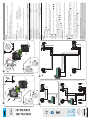
DELTA-SE: coppia di fotocellule da esterno.
DELTA-SI: coppia di fotocellule da incasso completa di contenitore.
Ogni installazione e uso di ormi da quanto indicato nel seguente manuale sono da considerarsi
vietate.
Componenti
1. Base del contenitore
2. Base del contenitore con predisposizione
pressacavo PG7
3. Base per montaggio ad incasso
4. Coperchio del contenitore
5. Scheda elettronica
6. Viti di fi ssaggio scheda
7. Viti* + OR per fi ssaggio della base
8. Vite di fi ssaggio coperchio
* DELTA-SE: viti non fornite; da scegliere secondo il tipo di fi ssaggio (max ø 4 mm).
Dati tecnici
Tipo
DELTA-SE DELTA-SI
Lunghezza onda (nm) 880
Alimentazione (V-
50/60 Hz)
12-24 AC-DC
Portata relè a 24 V (mA)
500
Assorbimento a 24 V AC (mA)
70
Grado di protezione (IP) 54
Classe d’isolamento III
Temperatura di esercizio (°C) -20 ÷ 55
Dimensioni (mm)
70 x 70 x 36 70 x 70 x 16
Materiale ABS - Policarbonato
Montaggio
DELTA-SE / DELTA-SI
- Fissare le fotocellule ( o ) a un’altezza di circa 50 cm da terra (le fotocellule devono essere
una di fronte all'altra).
- Forare il lato posteriore delle basi contenitore per far passare i cavi, e fi ssare le basi
usando gli OR forniti (per DELTA-SI è consigliato usare un pressacavo ).
DELTA-SE
- Fissare con le viti fornite le schede TX e RX e collegarle come da schemi ,o .
DELTA-SI
- Su muratura predisporre i contenitori a incasso DOC-S ,su pilastri in ferro invece, forare con
una fresa a tazza Ø 60 per introdurre le basi contenitore .
- Collegare le schede TX e RX come da schemi ,o , inserirle sulle basi dei contenitori,
facendole scorrere nelle apposite guide .
DELTA-SE / DELTA-SI
- Chiudere con la vite le basi, agganciando e ruotando la parte frontale dall’alto verso il basso.
Collegamenti
Collegamento di 1 coppia di fotocellule in riapertura durante la chiusura.
Collegamento di 2 coppie di fotocellule ( esempio: DELTA-SI + DIR) in riapertura durante la chiusura.
Collegamento di 2 coppie di fotocellule una in riapertura durante la chiusura e una in stop
parziale .
Per i contatti di uscita C - NC, verifi care sempre le indicazioni relative al collegamento e alle
funzioni nel manuale del quadro di comando Came associato.
Per passare all’alimentazione a 12 V (24 V standard), ponticellare le piazzole sulle schede RX,
lato componenti su DELTA-SE ( ) o lato opposto su DELTA-SI ( ).
Il prodotto è conforme alle direttive di riferimento vigenti.
Smaltimento - Non disperdere nell’ambiente l’imballaggio e il dispositivo alla fine del ciclo di vita, ma
smaltirli seguendo le norme vigenti nel paese di utilizzo del prodotto. I componenti riciclabili riportano
simbolo e sigla del materiale.
I contenuti del manuale sono da ritenersi suscettibili di modifi ca in qualsiasi momento senza obbligo di preavviso.

FA01070M4A - 01/2018
FA01070M4A - 01/2018
ENGLISH
Description
Synchronized infrared-beam photocells, with 20 m range. DIR-series compatible.
DELTA-SE: a pair of outdoor photocells.
DELTA-SI: a pair of recess-mounted photocells complete with case.
Any installation and/or use other than that specifi ed in this manual is forbidden.
Components
1. Casing base
2. Casing set up to fi t the PG7 cable gland
3. Recess-mounting base
4. Casing cover
5. Control board
6. Board fi tting screws
7. Screws* + O-ring for fi tting the base
8. Cover fastening screw
* DELTA-SE: the screws are not included; choose depending on the type of fi tting (max ø 4 mm).
Technical data
Type
DELTA-SE DELTA-SI
Wavelength (nm)
880
Power source (V-
50/60 Hz)
12-24 AC-DC
Relay rated for 24 V (mA)
500
Draw at 24 V AC (mA)
70
Protection rating (IP)
54
Insulation class
III
Operating temperature (°C)
-20 ÷ 55
Dimensions (mm)
70 x 70 x 36 70 x 70 x 16
Material
ABS - Polycarbonate
Mounting
DELTA-SE / DELTA-SI
- Fit the photocells ( or ) at about 50 cm from the ground (the photocells must directly face
each other).
- Perforate the back of the casing bases to push through the cables, and fasten the bases
by using the issued O-rings (for DELTA-SI we suggest using a cable-gland) ).
DELTA-SE
- Use the supplied screws to fi t the TX and RX control boards and connect them up as
shown in diagrams ,or .
DELTA-SI
- Set up the DOC-S recess-mounted casings into a wall . If mounting, on iron posts, drill using
a hole saw Ø 60 to fi t the casing bases .
- Connect up the TX and RX control boards as shown in diagrams ,or , then fi t into
the casing bases, so they run on the corresponding rails .
DELTA-SE / DELTA-SI
- Tighten the screw to close the bases and hook and turn the front part from top to bottom.
Connections
Wiring diagram for one pair of reopening-during-closing photocells.
Wiring diagram for two pairs of reopening-during-closing photocells (for example: DELTA-SI + DIR).
Wiring diagram for two pairs of photocells. One in reopening-during-closing mode one in
partial-stop mode
For the C - NC output contacts, always check the corresponding instructions printed in the Came
control panel manual.
To switch the voltage to 12 V (24 V is standard), bridge the bump contacts on the RX control
boards - on the DELTA-SE they are fi tted on the components side ( ) or on the opposite side
on the DELTA-SI ( ).
FRANÇAIS
Description
Photocellules à rayon infrarouge synchronisé, portée 20 m. Compatible avec la série DIR.
DELTA-SE : paire de photocellules d'extérieur.
DELTA-SI : paire de photocellules avec boîtier à encastrer.
Toute installation et toute utilisation autres que celles qui sont indiquées dans ce manuel sont
interdites.
Composants
1. Base du boîtier
2. Base du boîtier avec application du passe-câble PG7
3. Base pour la fi xation par encastrement
4. Couvercle du boîtier
5. Carte électronique
6. Vis de fi xation de la carte
7. Vis* + OR pour la fi xation de la base
8. Vis de fi xation du couvercle
* DELTA-SE : vis non fournies ; à choisir selon le type de fi xation (max. ø 4 mm).
Données techniques
Type
DELTA-SE DELTA-SI
Longueur onde (nm)
880
Alimentation (V-
50/60 Hz)
12-24 AC-DC
Portée relais à 24 V (mA)
500
Absorption en 24 VAC (mA)
70
Degré de protection (IP)
54
Classe d'isolation
III
Température de fonctionnement (°C)
-20 / 55
Dimensions (mm)
70 x 70 x 36 70 x 70 x 16
Matériau
ABS - Polycarbonate
Montage
DELTA-SE / DELTA-SI
- Fixer les photocellules ( ou ) à une hauteur du sol d'environ 50 cm (les photocellules doivent se
trouver l'une en face de l'autre).
- Percer le côté postérieur des bases du boîtier pour faire passer les câbles, et fi xer les bases à
l'aide des joints toriques fournis (pour DELTA-SI, il est conseillé d'utiliser un passe-câble ).
DELTA-SE
- Fixer à l'aide des vis fournies les cartes TX et RX et les connecter comme indiqué sur les
schémas ,ou .
DELTA-SI
- En cas d'installation au mur, prévoir les boîtiers à encastrer DOC-S ,en cas d'application sur des
piliers en fer, percer par contre à l'aide d'une fraise à godet Ø 60 pour introduire les bases du
boîtier .
- Connecter les cartes TX et RX comme indiqué sur les schémas ,ou , les insérer sur les
bases des boîtiers en les faisant coulisser dans les glissières prévues à cet e et.
DELTA-SE / DELTA-SI
- Fermer les bases à l'aide de la vis en fi xant et en tournant la partie frontale de haut en bas.
Connexions
Connexion d'1 paire de photocellules en réouverture durant la fermeture.
Connexion de 2 paires de photocellules ( exemple : DELTA-SI + DIR) en réouverture durant la fermeture.
Connexion de 2 paires de photocellules, une en réouverture durant la fermeture l'autre en arrêt
partiel .
Pour les contacts de sortie F-NF, toujours contrôler les indications sur la connexion et les fonctions
dans le manuel du tableau de commande Came associé.
Pour passer à l'alimentation 12 V (24 V standard), shunter les bosses de connexion sur les cartes RX,
côté composants sur DELTA-SE ( ) ou côté opposé sur DELTA-SI ( ).
РУССКИЙ
Описание
Фотоэлементы с синхронизированными ИК-лучами, совместимые с серией DIR. Дальность действия: 20 м.
DELTA-SE: комплект накладных фотоэлементов.
DELTA-SI: комплект встраиваемых фотоэлементов с монтажным корпусом.
Запрещается использовать устройство не по назначению и устанавливать его методами, отличными
от описанных в настоящей инструкции.
Компоненты
1. Основание корпуса
2. Основание корпуса с возможностью
применения гермоввода PG7
3. Встраиваемое монтажное основание
4. Крышка корпуса
5. Электронная плата
6. Саморезы крепления платы
7. Винты* + Уплотнительное кольцо для
крепления основания
8. Винт крепления крышки
* DELTA-SE: винты не входят в комплект поставки; их необходимо подобрать с учетом типа монтажной
поверхности (макс. ø 4 мм).
Технические характеристики
Модель
DELTA-SE DELTA-SI
Длина волны (нм) 880
Напряжение электропитания (В,
50/60 Гц)
~/=12 -24
Коммутируемый ток при 24 В (мА)
500
Потребляемый ток при напряжении ~24 В (мА)
70
Класс защиты (IP) 54
Класс изоляции III
Диапазон рабочих температур(°C) -20 — 55
Габаритные размеры (мм)
70 x 70 x 36 70 x 70 x 16
Материал ABS-пластик / поликарбонат
Монтаж
DELTA-SE / DELTA-SI
- Прикрепите фотоэлементы ( или ) на высоте около 50 см над землей (фотоэлементы должны
располагаться друг против друга).
- Просверлите заднюю стенку основания корпуса для проводки кабелей и зафиксируйте основания,
используя прилагаемые уплотнительные кольца (для модели DELTA-SI рекомендуется использовать
гермоввод ).
DELTA-SE
- Зафиксируйте прилагаемыми винтами платы фотоэлементов-передатчиков и приемников и
подключите их, как показано на схемах ,или .
DELTA-SI
- Для настенного монтажа подготовьте встраиваемые корпуса DOC-S .Просверлите отверстия корончатым
сверлом Ø 60 на железных стойках для установки оснований корпусов .
- Подключите платы фотоэлементов-передатчиков и приемников , как показано на схемах ,или .
Вставьте их в основания корпусов, перемещая вдоль направляющих .
DELTA-SE / DELTA-SI
- Закройте основания винтом , прикрепив и повернув переднюю крышку сверху вниз.
Подключения
Подключение 1 комплекта фотоэлементов для работы в режиме "Открывание во время закрывания".
Подключение 2 комплектов фотоэлементов (например: DELTA-SI + DIR) в режиме "Открывание во
время закрывания".
Подключение 2 комплектов фотоэлементов: одного для работы в режиме "Открывание во время
закрывания" , другого — в режиме "Частичный стоп" .
(*) При подключении контактов C-NC необходимо руководствоваться указаниями относительно подключения
и функций в соответствующем разделе инструкции по монтажу используемого блока управления Came.
Для перехода на электропитание 12 В (стандартные 24 В) установите перемычку на платах приемника:
со стороны компонентов на DELTA-SE ( ) или противоположной стороны на DELTA-SI ( ).
Изделие соответствует требованиям действующих нормативов.
Утилизация - Не выбрасывайте упаковку и устройство в окружающую среду. Утилизируйте их в соответствии с
требованиями законодательства, действующего в стране установки. На компоненты, подлежащие переработке,
нанесены знак и символ материала.
Содержание инструкции может быть изменено в любое время и без предварительного уведомления.
Le produit est conforme aux directives de référence en vigueur.
Élimination- Ne pas jeter l'emballage et le dispositif dans la nature au terme du cycle de vie de ce dernier, mais les
éliminer selon les normes en vigueur dans le pays où le produit est utilisé. Le symbole et le sigle du matériau fi gurent
sur les composants recyclables.
Le contenu du manuel est susceptible de subir des modifi cations à tout moment et sans aucun préavis.
The product complies to the reference regulations in effect.
Disposal- Dispose of the packaging and the device properly at the end of its life cycle, following the applicable laws in the
country where the device is installed. The recyclable components all bear a symbol.
The contents of this manual may be revised at any time, and without notice.
-
 1
1
-
 2
2


CAME DELTA-SI, DELTA-SE Guida d'installazione
- Tipo
- Guida d'installazione
in altre lingue
Documenti correlati
-
CAME DELTA-E, DELTA-I Guida d'installazione
-
-
-
-
-
CAME EMEGA Guida d'installazione
-
-
-