
Installation and
Getting Started Guide
www.procurve.com
ProCurve Wireless Access Point 530
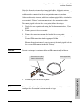
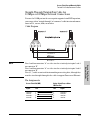
Power over Ethernet Devices
In


ProCurve
Wireless Access Point 530
Installation and Getting Started Guide

Hewlett-Packard Company
8000 Foothills Boulevard, m/s 5552
Roseville, California 95747-5552
http://www.procurve.com
© Copyright 2008 Hewlett-Packard Development Company,
L.P. The information contained herein is subject to change
without notice.
This document contains proprietary information, which is
protected by copyright. No part of this document may be
photocopied, reproduced, or translated into another language
without the prior written consent of Hewlett-Packard.
Publication Number
5992-5444
October 2008
Applicable Products
Disclaimer
HEWLETT-PACKARD COMPANY MAKES NO WARRANTY
OF ANY KIND WITH REGARD TO THIS MATERIAL,
INCLUDING, BUT NOT LIMITED TO, THE IMPLIED
WARRANTIES OF MERCHANTABILITY AND FITNESS
FOR A PARTICULAR PURPOSE. Hewlett-Packard shall not be
liable for errors contained herein or for incidental or consequential
damages in connection with the furnishing, performance, or use
of this material.
The only warranties for HP products and services are set forth in
the express warranty statements accompanying such products and
services. Nothing herein should be construed as constituting an
additional warranty. HP shall not be liable for technical or editorial
errors or omissions contained herein.
Hewlett-Packard assumes no responsibility for the use or
reliability of its software on equipment that is not furnished by
Hewlett-Packard.
Warranty
See the Customer Support/Warranty booklet included with the
product.
A copy of the specific warranty terms applicable to your Hewlett-
Packard products and replacement parts can be obtained from your
HP Sales and Service Office or authorized dealer.
Safety
Before installing and operating these products, please read the
“Installation Precautions” in chapter 2, “Installing the Access
Point 530”, and the safety statements in appendix C, “Safety and
EMC Regulatory Statements”.
Open Source Software Acknowledgement
Statement
This software incorporates open source components that
are governed by the GNU General Public License (GPL),
version 2. In accordance with this license, ProCurve
Networking will make available a complete, machine-
readable copy of the source code components covered by
the GNU GPL upon receipt of a written request. Send a
request to:
Hewlett-Packard Company, L.P.
AP 530 Program
GNU GPL Source Code
Attn: ProCurve Networking Support
MS: 5551
Roseville, CA 95747 USA
Open source licenses pertaining to the open source software
included with the product can be found in Appendix C in this
guide.
ProCurve Wireless Access Point 530 NA (J8986A)
ProCurve Wireless Access Point 530 WW (J8987A)

i
Contents
1 Introducing the ProCurve Wireless Access Point 530
Top of the Access Point . . . . . . . . . . . . . . . . . . . . . . . . . . . . . . . . . . . . . . . . 1-3
LEDs . . . . . . . . . . . . . . . . . . . . . . . . . . . . . . . . . . . . . . . . . . . . . . . . . . . . . . 1-4
Back of the Access Point . . . . . . . . . . . . . . . . . . . . . . . . . . . . . . . . . . . . . . 1-5
Back Panel Covers . . . . . . . . . . . . . . . . . . . . . . . . . . . . . . . . . . . . . . . . . . 1-5
Antennas . . . . . . . . . . . . . . . . . . . . . . . . . . . . . . . . . . . . . . . . . . . . . . . . . . . 1-5
Console Port . . . . . . . . . . . . . . . . . . . . . . . . . . . . . . . . . . . . . . . . . . . . . . . 1-6
Network Port . . . . . . . . . . . . . . . . . . . . . . . . . . . . . . . . . . . . . . . . . . . . . . . 1-6
Power Connector . . . . . . . . . . . . . . . . . . . . . . . . . . . . . . . . . . . . . . . . . . . 1-6
Reset Button . . . . . . . . . . . . . . . . . . . . . . . . . . . . . . . . . . . . . . . . . . . . . . . 1-7
Clear Button . . . . . . . . . . . . . . . . . . . . . . . . . . . . . . . . . . . . . . . . . . . . . . . . 1-8
Auxiliary Port . . . . . . . . . . . . . . . . . . . . . . . . . . . . . . . . . . . . . . . . . . . . . . . 1-8
Access Point Features . . . . . . . . . . . . . . . . . . . . . . . . . . . . . . . . . . . . . . . . . 1-9
Getting Documentation from the Web . . . . . . . . . . . . . . . . . . . . . . . . . 1-10
2 Installing the Access Point 530
Included Parts . . . . . . . . . . . . . . . . . . . . . . . . . . . . . . . . . . . . . . . . . . . . . . . . 2-1
Installation Procedures . . . . . . . . . . . . . . . . . . . . . . . . . . . . . . . . . . . . . . . . 2-2
Summary . . . . . . . . . . . . . . . . . . . . . . . . . . . . . . . . . . . . . . . . . . . . . . . . . . . 2-2
Installation Precautions: . . . . . . . . . . . . . . . . . . . . . . . . . . . . . . . . . . . . . . 2-3
1. Prepare the Installation Site . . . . . . . . . . . . . . . . . . . . . . . . . . . . . . . . 2-4
2. Verify the Access Point Completes Initialization . . . . . . . . . . . . . . . 2-5
LED Behavior: . . . . . . . . . . . . . . . . . . . . . . . . . . . . . . . . . . . . . . . . . . 2-6
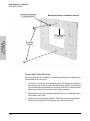
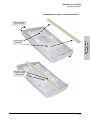
3. Mount the Access Point . . . . . . . . . . . . . . . . . . . . . . . . . . . . . . . . . . . . 2-7
Wall Mounting . . . . . . . . . . . . . . . . . . . . . . . . . . . . . . . . . . . . . . . . . . . 2-7
Standard Electrical Box Mounting . . . . . . . . . . . . . . . . . . . . . . . . . . 2-9
Suspended Ceiling Mounting . . . . . . . . . . . . . . . . . . . . . . . . . . . . . 2-10
Horizontal Surface Mounting . . . . . . . . . . . . . . . . . . . . . . . . . . . . . 2-12
4. Connect the Access Point to a Power Source . . . . . . . . . . . . . . . . . 2-12
5. Connect the Network Cable . . . . . . . . . . . . . . . . . . . . . . . . . . . . . . . . 2-13
Using the RJ-45 Connectors . . . . . . . . . . . . . . . . . . . . . . . . . . . . . . 2-13

ii
6. (Optional) Connect External Antennas to the Access Point . . . . . 2-13
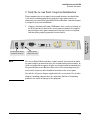
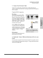
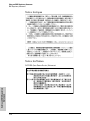
7. (Optional) Connect a Console to the Access Point 530 . . . . . . . . . 2-14
Terminal Configuration . . . . . . . . . . . . . . . . . . . . . . . . . . . . . . . . . . 2-14
Direct Console Access . . . . . . . . . . . . . . . . . . . . . . . . . . . . . . . . . . . 2-15
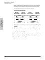
Sample Network Topologies . . . . . . . . . . . . . . . . . . . . . . . . . . . . . . . . . . 2-17
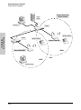
Infrastructure Wireless LAN . . . . . . . . . . . . . . . . . . . . . . . . . . . . . . . . . 2-18
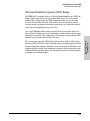
Infrastructure Wireless LAN with Roaming . . . . . . . . . . . . . . . . . . . . . 2-19
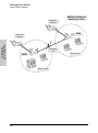
Wireless Distribution System (WDS) Bridge . . . . . . . . . . . . . . . . . . . . 2-21
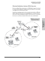
Wireless Distribution System (WDS) Repeater . . . . . . . . . . . . . . . . . . 2-23
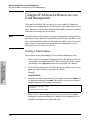
3 Getting Started With Access Point Configuration
Recommended Minimal Configuration . . . . . . . . . . . . . . . . . . . . . . . . . . 3-1
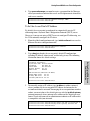
Using the Command Line Interface . . . . . . . . . . . . . . . . . . . . . . . . . . . . 3-2
To Set the Manager User Name and Password . . . . . . . . . . . . . . . 3-2
To Set the Access Point’s IP Address . . . . . . . . . . . . . . . . . . . . . . . 3-3
To Set the Access Point’s Country Code . . . . . . . . . . . . . . . . . . . . . 3-4
To Configure Radio Settings . . . . . . . . . . . . . . . . . . . . . . . . . . . . . . . 3-5
Where to Go From Here . . . . . . . . . . . . . . . . . . . . . . . . . . . . . . . . . . . . . . 3-9
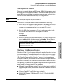
Using the IP Address for Remote Access Point Management . . . . 3-10
Starting a Telnet Session . . . . . . . . . . . . . . . . . . . . . . . . . . . . . . . . . . . . 3-10
Starting an SSH Session . . . . . . . . . . . . . . . . . . . . . . . . . . . . . . . . . . . . . 3-11
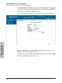
Starting a Web Browser Session . . . . . . . . . . . . . . . . . . . . . . . . . . . . . . 3-11
4 Using an External Antenna with the Access Point 530
External Antenna Options . . . . . . . . . . . . . . . . . . . . . . . . . . . . . . . . . . . . . 4-2
Installation Procedures . . . . . . . . . . . . . . . . . . . . . . . . . . . . . . . . . . . . . . . . 4-3
1. Plan the Installation . . . . . . . . . . . . . . . . . . . . . . . . . . . . . . . . . . . . . . . 4-3
2. Mount the Antenna . . . . . . . . . . . . . . . . . . . . . . . . . . . . . . . . . . . . . . . . 4-4
3. Connect Pigtail Cables to the Access Point . . . . . . . . . . . . . . . . . . . . 4-4
4. Configure the Antenna Mode and Type . . . . . . . . . . . . . . . . . . . . . . . 4-6
Setting the Antenna Mode and Type Using the CLI . . . . . . . . . . . . 4-6
Setting the Antenna Mode and Type Using the Web Interface . . . 4-6

iii
5 Troubleshooting
Basic Troubleshooting Tips . . . . . . . . . . . . . . . . . . . . . . . . . . . . . . . . . . . . 5-1
Diagnosing with the LEDs . . . . . . . . . . . . . . . . . . . . . . . . . . . . . . . . . . . . . 5-3
Proactive Networking . . . . . . . . . . . . . . . . . . . . . . . . . . . . . . . . . . . . . . . . . 5-6
Hardware Diagnostic Tests . . . . . . . . . . . . . . . . . . . . . . . . . . . . . . . . . . . . 5-7
Testing the Access Point by Resetting It . . . . . . . . . . . . . . . . . . . . . . . . 5-7
Checking the Access Point’s LEDs . . . . . . . . . . . . . . . . . . . . . . . . . 5-7
Checking Event Messages . . . . . . . . . . . . . . . . . . . . . . . . . . . . . . . . . 5-7
Testing Twisted-Pair Cabling . . . . . . . . . . . . . . . . . . . . . . . . . . . . . . . . . . 5-8
Testing Access Point-to-Device Network Communications . . . . . . . . 5-8
Testing End-to-End Network Communications . . . . . . . . . . . . . . . . . . 5-8
Restoring Custom and Factory Default Configurations . . . . . . . . . . 5-9
Downloading New Access Point Software . . . . . . . . . . . . . . . . . . . . . . 5-11
HP Customer Support Services . . . . . . . . . . . . . . . . . . . . . . . . . . . . . . . . 5-11
Before Calling Support . . . . . . . . . . . . . . . . . . . . . . . . . . . . . . . . . . . . . . 5-11
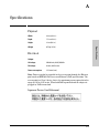
A Specifications
Physical . . . . . . . . . . . . . . . . . . . . . . . . . . . . . . . . . . . . . . . . . . . . . . . . . . A-1
Electrical . . . . . . . . . . . . . . . . . . . . . . . . . . . . . . . . . . . . . . . . . . . . . . . . . A-1
Japanese Power Cord Statement . . . . . . . . . . . . . . . . . . . . . . . . . A-1
Environmental . . . . . . . . . . . . . . . . . . . . . . . . . . . . . . . . . . . . . . . . . . . . A-2
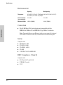
Connectors . . . . . . . . . . . . . . . . . . . . . . . . . . . . . . . . . . . . . . . . . . . . . . . . A-2
Safety . . . . . . . . . . . . . . . . . . . . . . . . . . . . . . . . . . . . . . . . . . . . . . . . . . . . A-2
EMC Compliance (Class B) . . . . . . . . . . . . . . . . . . . . . . . . . . . . . . . . . . A-2
Radio Signal Certification . . . . . . . . . . . . . . . . . . . . . . . . . . . . . . . . . . . A-3
Immunity . . . . . . . . . . . . . . . . . . . . . . . . . . . . . . . . . . . . . . . . . . . . . . . . . A-3
Wireless . . . . . . . . . . . . . . . . . . . . . . . . . . . . . . . . . . . . . . . . . . . . . . . . . . A-3
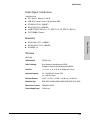
Receiver Sensitivity . . . . . . . . . . . . . . . . . . . . . . . . . . . . . . . . . . . . . . . . . A-5
Internal Antenna . . . . . . . . . . . . . . . . . . . . . . . . . . . . . . . . . . . . . . . . . . . A-5
B Access Point Port and Network Cables
Access Point Ports . . . . . . . . . . . . . . . . . . . . . . . . . . . . . . . . . . . . . . . . . B-1
Twisted-Pair Cables . . . . . . . . . . . . . . . . . . . . . . . . . . . . . . . . . . . . . . . . B-1

iv
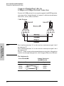
Twisted-Pair Cable/Connector Pin-Outs . . . . . . . . . . . . . . . . . . . . . . . B-2
Straight-Through Twisted-Pair Cable for
10 Mbps or 100 Mbps Network Connections . . . . . . . . . . . . . . . . . . . . B-3
Cable Diagram . . . . . . . . . . . . . . . . . . . . . . . . . . . . . . . . . . . . . . . . . B-3
Pin Assignments . . . . . . . . . . . . . . . . . . . . . . . . . . . . . . . . . . . . . . . B-3
Crossover Twisted-Pair Cable for
10 Mbps or 100 Mbps Network Connection . . . . . . . . . . . . . . . . . . . . . B-4
Cable Diagram . . . . . . . . . . . . . . . . . . . . . . . . . . . . . . . . . . . . . . . . . B-4
Pin Assignments . . . . . . . . . . . . . . . . . . . . . . . . . . . . . . . . . . . . . . . B-4
C Safety and EMC Regulatory Statements
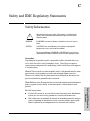
Safety Information . . . . . . . . . . . . . . . . . . . . . . . . . . . . . . . . . . . . . . . . . . . C-1
Informations concernant la sécurité . . . . . . . . . . . . . . . . . . . . . . . . . . . C-2
Hinweise zur Sicherheit . . . . . . . . . . . . . . . . . . . . . . . . . . . . . . . . . . . . . . C-3
Considerazioni sulla sicurezza . . . . . . . . . . . . . . . . . . . . . . . . . . . . . . . . C-5
Consideraciones sobre seguridad . . . . . . . . . . . . . . . . . . . . . . . . . . . . . C-6
Safety Information (Japan) . . . . . . . . . . . . . . . . . . . . . . . . . . . . . . . . . . . C-8
Safety Information (Korea) . . . . . . . . . . . . . . . . . . . . . . . . . . . . . . . . . . . C-9
Safety Information (China) . . . . . . . . . . . . . . . . . . . . . . . . . . . . . . . . . . C-10
EMC Regulatory Statements . . . . . . . . . . . . . . . . . . . . . . . . . . . . . . . . . C-11
Notice for U.S.A. . . . . . . . . . . . . . . . . . . . . . . . . . . . . . . . . . . . . . . . . . . C-11
Regulatory Model Identification Number . . . . . . . . . . . . . . . . . . C-12
Notice for Canada . . . . . . . . . . . . . . . . . . . . . . . . . . . . . . . . . . . . . . . . . C-12
Notice for European Community . . . . . . . . . . . . . . . . . . . . . . . . . . . . C-13
Supported Antennas . . . . . . . . . . . . . . . . . . . . . . . . . . . . . . . . . . . . . . . C-16
EU Declaration of Conformity . . . . . . . . . . . . . . . . . . . . . . . . . . . . . . . C-17
Notice for Japan . . . . . . . . . . . . . . . . . . . . . . . . . . . . . . . . . . . . . . . . . . C-18
Notice for Taiwan . . . . . . . . . . . . . . . . . . . . . . . . . . . . . . . . . . . . . . . . . C-18
Notice for Korea . . . . . . . . . . . . . . . . . . . . . . . . . . . . . . . . . . . . . . . . . . C-19
Licenses . . . . . . . . . . . . . . . . . . . . . . . . . . . . . . . . . . . . . . . . . . . . . . . . . . . . C-19
D Recycle Statements
Waste Electrical and Electronic Equipment (WEEE) Statements D-1

1-1
Introducing the ProCurve
Wireless Access Point 530
1
Introducing the ProCurve
Wireless Access Point 530
The ProCurve Wireless Access Point 530 is an enterprise-class, dual-radio
802.11b/g and 802.11a/b/g access point that offers maximum flexibility in
deployment and optimum throughput for high-density usage areas.
The access point provides comprehensive security and management features
and is capable of supporting all types of wireless stations in the same coverage
area. The unit includes internal diversity antennas for both radios and also
connectors for attaching a variety of external antenna options. Mounting
options for the unit include horizontal surface, wall, suspended ceiling T-rail,
and plenum space.
Throughout this manual, this access point will be abbreviated as the
Access Point 530.
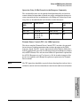
The Access Point 530 has one 10/100Base-TX RJ-45 port. This port also
supports Power over Ethernet (PoE) based on the IEEE 802.3af standard. The
access point supports wireless connectivity at speeds up to 54 Mbps based on
the IEEE 802.11g and IEEE 802.11a standards.
ProCurve Wireless Access Point 530 NA (J8986A)
ProCurve Wireless Access Point 530 WW (J8987A)

1-2
Introducing the ProCurve Wireless Access Point 530
Introducing the ProCurve
Wireless Access Point 530
This access point is designed to be used primarily for connecting wireless
stations to an enterprise network. This access point allows wireless stations
to connect directly to each other, or to connect to other computers or network
resources located on the wired network.
This chapter describes your Access Point 530 including:
■ Top and back of the access point
■ Access point features

1-3
Introducing the ProCurve Wireless Access Point 530
Top of the Access Point
Introducing the ProCurve
Wireless Access Point 530
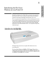
Top of the Access Point
ProCurve Wireless Access Point 530
Indicator Panel
Power LED
Ethernet LEDWireless LED
Back Panel Covers

1-4
Introducing the ProCurve Wireless Access Point 530
Top of the Access Point
Introducing the ProCurve
Wireless Access Point 530
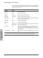
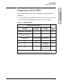
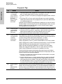
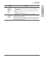
LEDs
Table 1-1. Access Point LEDs
Access Point
LEDs
State Meaning
Power
(green)
On The access point is receiving power.
Off The access point is NOT receiving power.
LAN
(green)
Off The RJ-45 port has no network cable connected, or is not receiving a link signal.
Blinking or
On
The RJ-45 port has a link indication from a 10 Mbps or 100 Mbps device and is
transmitting or receiving traffic. The LED blinking rate is proportional to the traffic
rate. If there is no traffic, the blinking rate will be once every five seconds. As the
traffic rate increases, the blinking rate also increases until the LED is solid on, which
indicates there no available bandwidth on the port.
Radio 1 (11b/g)
Radio 2 (11a/b/g)
(green)
Off The wireless interface is disabled, either through the access point console or the
Web browser interface.
Blinking or
On
The wireless interface is enabled and transmitting or receiving traffic. The LED
blinking rate is proportional to the traffic rate. If there is no traffic, the blinking rate
will be once every five seconds. As the traffic rate increases, the blinking rate also
increases until the LED is solid on, which indicates there no available bandwidth
on the interface.

1-5
Introducing the ProCurve Wireless Access Point 530
Back of the Access Point
Introducing the ProCurve
Wireless Access Point 530
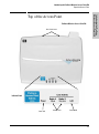
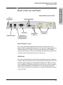
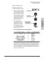
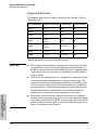
Back of the Access Point
Back Panel Covers
The access point’s ports and connectors on the back of the unit can be
protected by two removable plastic covers. One covers the Console port, Clear
and Reset buttons, RJ-45 port, and DC power connector, while allowing
twisted-pair and power cables to pass through. The other cover protects the
external antenna connectors when they are not in use.
Antennas
The access point includes internal diversity antennas for wireless communi-
cations. A diversity antenna system uses two identical antennas to receive and
transmit signals, helping to avoid multipath fading effects. When receiving,
the access point checks both antennas and selects the one with the strongest
signal. When transmitting, it will continue to use the antenna previously
selected for receiving. The access point never transmits from both antennas
at the same time.
Reset and Clear
buttons
External Antenna
connectors
ProCurve Wireless Access Point 530
Network port
10/100Base-TX RJ-45
port and PoE input
DC power connector
Console port
Lock
(on side panel)
Auxiliary port and LED

1-6
Introducing the ProCurve Wireless Access Point 530
Back of the Access Point
Introducing the ProCurve
Wireless Access Point 530
The access point also supports connectors for various external antenna
options that offer extended radio range and specific radio coverage patterns.
For further information, see chapter 4, “Using an External Antenna with the
Access Point 530”.
Lock
The access point includes a Kensington security slot on the side panel, marked
with the lock symbol ( ). You can prevent unauthorized removal of the
access point by wrapping the Kensington security cable (not provided) around
an unmovable object, inserting the lock into the slot, and turning the key.
Console Port
This port connects a console to the access point using a serial cable. This
connection is described under “Connect a Console to the Access Point” in
chapter 2, “Installing the Access Point 530”. The console can be a PC or
workstation running a VT-100 terminal emulator, or a VT-100 terminal.
Network Port
The access point includes one 10/100Base-TX port. This port uses the “HP Auto
MDIX” feature, which means that you can use either straight-through or
crossover twisted-pair cables to connect the access point to a switch or
workstation.
Refer to the following section for information on supplying power to the
access point through its RJ-45 port from a network device, such as a switch,
that provides Power over Ethernet (PoE).
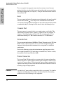
Power Connector
The Access Point 530 does not have a power switch; it is powered on when
connected to the AC power adapter, and the power adapter is connected to
an active AC power source. The access point's power adapter automatically
adjusts to any voltage between 100--240 volts and either 50 or 60 Hz. There are
no voltage range settings required.
Caution Use only the AC power adapter supplied with the access point. Use of other
adapters, including adapters that came with other ProCurve Networking
products, may result in damage to the equipment.

1-7
Introducing the ProCurve Wireless Access Point 530
Back of the Access Point
Introducing the ProCurve
Wireless Access Point 530
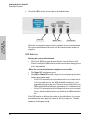
The access point may also receive Power over Ethernet (PoE) from a switch
or other network device that supplies power over the network cable based on
the IEEE 802.3af standard.
Note that if the access point is connected to a PoE source device and also
connected to a local power source through the AC power adapter, PoE will
be disabled.
Reset Button
This button is used to reset the hardware or restore the factory defaults:
■ To Reset the Access Point While it is Powered On – When the Reset
button is pressed for about one second all the LEDs turn off, then after
another second the LEDs start to blink rapidly. Releasing the button when
the LEDs are blinking rapidly clears any temporary error conditions that
may have occurred and restarts the access point initialization.
■ To Restore Custom Default Configuration – When pressed with the
Clear button in a specific pattern, any configuration changes you may have
made through the access point console or the Web browser interface are
removed, and the customer-specified default configuration is restored to
the access point. For the specific method to restore the customer default
configuration, see “Restoring Custom and Factory Default Configura-
tions” in chapter 5, “Troubleshooting” of this guide.
■ To Restore Factory Default Configuration – When pressed with the
Clear button in a specific pattern, any configuration changes you may have
made through the access point console or the Web browser interface are
removed, and the factory default configuration is restored to the access
point. For the specific method to restore the factory default configuration,
see “Restoring Custom and Factory Default Configurations” in chapter 5,
“Troubleshooting” of this guide.
Note The system, password, custom default, and factory default reset functions can
be disabled by the access point’s software. For more information, see the
Management and Configuration Guide, which is available for download on
the ProCurve Networking Web site at http://www.procurve.com/manuals.

1-8
Introducing the ProCurve Wireless Access Point 530
Back of the Access Point
Introducing the ProCurve
Wireless Access Point 530
Clear Button
This button is used for these purposes:
■ Deleting the Password - When pressed by itself for at least one second,
the button resets the Manager password to the factory default setting for
all of the access point’s interfaces. Use this feature if you have misplaced
the password and need management access.
■ To Restore Custom Default Configuration – When pressed with the
Reset button in a specific pattern, any configuration changes you may
have made through the access point console or the Web browser interface
are removed, and the customer-specified default configuration is restored
to the access point. For the specific method to restore the customer
default configuration, see “Restoring Custom and Factory Default Config-
urations” in chapter 5, “Troubleshooting” of this guide.
■ Restoring Factory Default Configuration - When pressed with the
Reset button in a specific pattern, any configuration changes you may
have made through the console, the Web browser interface, and SNMP
management are removed, and the factory default configuration is
restored to the access point. For the specific method to restore the factory
default configuration, see “Restoring Custom and Factory Default Config-
urations” in chapter 5, “Troubleshooting” of this guide.
Auxiliary Port
The Auxiliary port is reserved for future use.

1-9
Introducing the ProCurve Wireless Access Point 530
Access Point Features
Introducing the ProCurve
Wireless Access Point 530
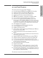
Access Point Features
The wireless features of the Access Point 530 include:
■ dual-radio design with IEEE 802.11b/g and IEEE 802.11a/b/g radios
■ supports up to 16 Service Set IDentifier (SSID) interfaces
■ independent security and VLAN settings per SSID interface
■ supports up to 256 wireless stations per radio interface
■ IEEE 802.11a/b/g compliant – interoperable with multiple vendors
■ precise control over signal transmission power and data rate
■ advanced security through 64/128/152-bit WEP encryption, Wi-Fi
Protected Access (WPA and WPA2), IEEE 802.1X, remote authentication
via a RADIUS server, and MAC address filtering features to protect your
sensitive data and authenticate only authorized users to your network
■ remote logging of system messages
■ time synchronization via SNTP server for message logs
■ wireless bridging between access points
■ neighbor access point detection
■ Quality of Service (QoS) support through Wi-Fi Multimedia (WMM) and
Spectralink Voice Priority (SVP)
■ secured authentication of wireless clients through the client’s Web
browser
■ Adaptive Transmit Power Control, to minimize same-channel interference
and maximize channel coverage
■ support for SNMP audible client/PROBE requests (requires PMM 2.0)
■ support for automatic configuration of a group of Access Point 530s
■ de-authentication and lockout of individual clients by MAC address
■ secure authentication of the Access Point 530 on network ports protected
by 802.1X port-based authentication
■ group configuration of up to 12 access points
■ support for wireless sFlow
■ auto channel selection – simplifies deployment by testing all available
channels and selecting the best channel based on signal-to-noise ratio
■ international country configuration – select the appropriate country and
the access point automatically configures radio operation to match regu-
latory requirements (model J8987A only)
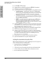
The other basic features of the Access Point 530 include:

1-10
Introducing the ProCurve Wireless Access Point 530
Access Point Features
Introducing the ProCurve
Wireless Access Point 530
■ one 10/100Base-TX RJ-45 port
■ supports Power over Ethernet based on the IEEE 802.3af standard
■ full-duplex operation for the 10/100 RJ-45 port
■ easy management of the access point through several available interfaces:
• console interface—a full featured, easy to use, VT-100 terminal
interface that is especially good for out-of-band access point manage-
ment and for Telnet or Secure Shell access to the access point
• Web browser interface—an easy to use built-in graphical interface
that can be accessed from common Web browsers (includes support
for secure HTTP connections)
• SNMP—a network management application such as HP ProCurve
Manager can manage the access point via the Simple Network
Management Protocol (SNMP) from a network management station
(supports SNMP versions 1, 2c, and 3)
■ support for IEEE 802.1Q-compliant VLANs (as specified for each station
in the RADIUS server) so that wireless stations can join the appropriate
logical grouping for the network user’s needs
■ support for Identity Driven Management and RADIUS assigned VLANs
■ RADIUS Accounting for logging user activity on the network
■ support for many advanced features to enhance network performance—
for a description, see the Management and Configuration Guide, which
is available for download on the ProCurve Networking Web site at
http://www.procurve.com/manuals.
■ download of new access point software for software updates
■ upload and download of access point configuration files
Getting Documentation from the Web
PDF versions of this document, the AP-530 Management and Configuration
Guide, and release notes are available online.
1. Go to the ProCurve Networking Web site at
http://www.procurve.com/manuals
2. Click on the name of the product for which you want documentation.
3. On the resulting web page, double-click on a document you want.
4. Save the document to your hard disk.

2-1
Installing the
Access Point 530
2
Installing the Access Point 530
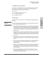
The Access Point 530 is easy to install. It comes with an accessory kit that
includes a bracket for mounting the access point on a wall or to a suspended
ceiling T-rail. The bracket is designed to allow mounting the access point in a
variety of locations and orientations.
This chapter shows you how to install your Access Point 530.
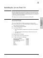
Included Parts
The Access Point 530 has the following components shipped with it:
■ ProCurve Wireless Access Point 530 Installation and Getting Started
Guide (5992-5444), this manual
■ Customer Support/Warranty booklet
■ Accessory kit (5070-1657)
• four 5/8-inch number 12 wood screws to attach the access point to a
wall
• four plastic wall plugs for mounting on a brick or concrete wall
• four rubber feet
■ Mounting bracket (5188-4682)
■ AC power adapter (5188-3767 or 5189-2946)
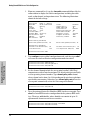
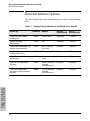
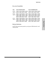
■ AC power cord, one of the following:
United States/Canada/Mexico
Continental Europe
United Kingdom/Hong Kong/Singapore
Australia/New Zealand
Japan
China
Denmark
Switzerland
8120-0740
8121-0731
8121-0739
8121-0730
8121-0736
8121-0742
8121-0733
8121-0738

2-2
Installing the Access Point 530
Installation Procedures
Installing the
Access Point 530
Installation Procedures
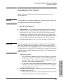
Summary
Follow these easy steps to install your access point. The rest of this chapter
provides details on these steps.
1. Prepare the installation site (page 2-4). Make sure that the physical
environment into which you will be installing the access point is properly
prepared, including having the correct network cabling ready to connect
to the access point and having an appropriate location for the access
point. Please see page 2-2 for some installation precautions.
2. Verify that the access point completes its system initialization
(page 2-5). This is a simple process of plugging the access point into a
power source, or connecting it to a switch that provides Power over
Ethernet, and observing that the LEDs on the access point’s top panel
indicate correct access point operation.
3. Mount the access point (page 2-7). The Access Point 530 can be
mounted on a wall, on a suspended ceiling T-rail, or on a horizontal
surface.
4. Connect power to the access point (page 2-12). Once the access
point is mounted, plug it into a nearby main power source, or connect it
to a switch that provides Power over Ethernet.
5. Connect to the network (page 2-13). Using the appropriate network
cable, connect the access point to a network connection point, such as a
switch. The network connection can also be used to provide power to the
access point through its PoE feature.
6. Connect a console to the access point (optional—page 2-14). You
may wish to modify the access point’s configuration, for example, to
configure an IP address so it can be managed using a Web browser or
through a Telnet session. Configuration changes can be made easily by
using a console cable to connect a PC to the access point’s console port.
At this point, your access point is fully installed. See the rest of this chapter if
you need more detailed information on any of these installation steps.
La pagina si sta caricando...
La pagina si sta caricando...
La pagina si sta caricando...
La pagina si sta caricando...
La pagina si sta caricando...
La pagina si sta caricando...
La pagina si sta caricando...
La pagina si sta caricando...
La pagina si sta caricando...
La pagina si sta caricando...
La pagina si sta caricando...
La pagina si sta caricando...
La pagina si sta caricando...
La pagina si sta caricando...
La pagina si sta caricando...
La pagina si sta caricando...
La pagina si sta caricando...
La pagina si sta caricando...
La pagina si sta caricando...
La pagina si sta caricando...
La pagina si sta caricando...
La pagina si sta caricando...
La pagina si sta caricando...
La pagina si sta caricando...
La pagina si sta caricando...
La pagina si sta caricando...
La pagina si sta caricando...
La pagina si sta caricando...
La pagina si sta caricando...
La pagina si sta caricando...
La pagina si sta caricando...
La pagina si sta caricando...
La pagina si sta caricando...
La pagina si sta caricando...
La pagina si sta caricando...
La pagina si sta caricando...
La pagina si sta caricando...
La pagina si sta caricando...
La pagina si sta caricando...
La pagina si sta caricando...
La pagina si sta caricando...
La pagina si sta caricando...
La pagina si sta caricando...
La pagina si sta caricando...
La pagina si sta caricando...
La pagina si sta caricando...
La pagina si sta caricando...
La pagina si sta caricando...
La pagina si sta caricando...
La pagina si sta caricando...
La pagina si sta caricando...
La pagina si sta caricando...
La pagina si sta caricando...
La pagina si sta caricando...
La pagina si sta caricando...
La pagina si sta caricando...
La pagina si sta caricando...
La pagina si sta caricando...
La pagina si sta caricando...
La pagina si sta caricando...
La pagina si sta caricando...
La pagina si sta caricando...
La pagina si sta caricando...
La pagina si sta caricando...
La pagina si sta caricando...
La pagina si sta caricando...
La pagina si sta caricando...
La pagina si sta caricando...
La pagina si sta caricando...
La pagina si sta caricando...
La pagina si sta caricando...
La pagina si sta caricando...
La pagina si sta caricando...
La pagina si sta caricando...
La pagina si sta caricando...
La pagina si sta caricando...
La pagina si sta caricando...
La pagina si sta caricando...
La pagina si sta caricando...
La pagina si sta caricando...
La pagina si sta caricando...
La pagina si sta caricando...
La pagina si sta caricando...
La pagina si sta caricando...
La pagina si sta caricando...
La pagina si sta caricando...
La pagina si sta caricando...
La pagina si sta caricando...
La pagina si sta caricando...
La pagina si sta caricando...
La pagina si sta caricando...
La pagina si sta caricando...
La pagina si sta caricando...
La pagina si sta caricando...
-
 1
1
-
 2
2
-
 3
3
-
 4
4
-
 5
5
-
 6
6
-
 7
7
-
 8
8
-
 9
9
-
 10
10
-
 11
11
-
 12
12
-
 13
13
-
 14
14
-
 15
15
-
 16
16
-
 17
17
-
 18
18
-
 19
19
-
 20
20
-
 21
21
-
 22
22
-
 23
23
-
 24
24
-
 25
25
-
 26
26
-
 27
27
-
 28
28
-
 29
29
-
 30
30
-
 31
31
-
 32
32
-
 33
33
-
 34
34
-
 35
35
-
 36
36
-
 37
37
-
 38
38
-
 39
39
-
 40
40
-
 41
41
-
 42
42
-
 43
43
-
 44
44
-
 45
45
-
 46
46
-
 47
47
-
 48
48
-
 49
49
-
 50
50
-
 51
51
-
 52
52
-
 53
53
-
 54
54
-
 55
55
-
 56
56
-
 57
57
-
 58
58
-
 59
59
-
 60
60
-
 61
61
-
 62
62
-
 63
63
-
 64
64
-
 65
65
-
 66
66
-
 67
67
-
 68
68
-
 69
69
-
 70
70
-
 71
71
-
 72
72
-
 73
73
-
 74
74
-
 75
75
-
 76
76
-
 77
77
-
 78
78
-
 79
79
-
 80
80
-
 81
81
-
 82
82
-
 83
83
-
 84
84
-
 85
85
-
 86
86
-
 87
87
-
 88
88
-
 89
89
-
 90
90
-
 91
91
-
 92
92
-
 93
93
-
 94
94
-
 95
95
-
 96
96
-
 97
97
-
 98
98
-
 99
99
-
 100
100
-
 101
101
-
 102
102
-
 103
103
-
 104
104
-
 105
105
-
 106
106
-
 107
107
-
 108
108
-
 109
109
-
 110
110
-
 111
111
-
 112
112
-
 113
113
-
 114
114


in altre lingue
- English: HP 530 User manual
Altri documenti
-
EnGenius ENS500EXT-AC Manuale utente
-
Allied Telesyn International Corp FS708/POE Guida d'installazione
-
Aruba 600R Series Remote Access Points Guida utente
-
Senao Networks ZoneFlex 7731 Manuale utente
-
-
Lindy 52022 Manuale utente
-
Xerox FAX ATA 101S Manuale del proprietario
-
i-PRO i-PRO WV-S71300-F3 Network Camera Manuale utente
-
ZyXEL WAP6405 Manuale utente
-
Senao Networks ENH202 Manuale utente