
DUB02CXXX
PUB02CXXX
1-phase voltage monitoring relay
1-phasiges Spannungsüberwachungsrelais
Relais de contrôle de tension monophasée
Relé de control de tensión monofásica
Relè di tensione monofase
1-faset spændingsmålerelæ
Installation instructions
Installationshinweise
Notice d’installation
Instrucciones de instalación
Istruzioni per l’installazione
Installationsvejledning
Mounting and installation by skilled people only!
Montage und Installation nur durch Fachpersonal!
Montage et installation par des personnes habilitées seulement!
El montaje e instalación ha de realizarlo solo personal con experiencia!
Il montaggio e l’installazione va eseguito da parte di personale addestrato!
Montering og installation må kun foretages af faguddannede personer!
ENGLISH DEUTSCH
FRANÇAIS
ESPAÑOL
ITALIANO DANSK
j
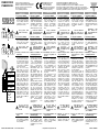
Connections (DUB02)
Connect the power supply
to the proper terminals and
the relay output according
to the ratings. Automatic
screwdriver can be used
(max torque 0.5 Nm).
Keep power OFF
while connecting!
k
Connections (PUB02)
Connect the power sup
-
ply to the proper terminals.
Connect the relay output
according to the ratings.
Keep power OFF
while connecting!
l
Setting of function and
input range
Adjust the input range set
-
ting the DIP switches 5 and
6. Select the desired func
-
tion setting the DIP switch-
es 1 to 4. To access the DIP
switches open the plastic
cover using a screwdriver
as shown on the left.
SW1 selects the delay
mode: delay on recovery
(delay occurs between the
end of the alarm condition
and the switching of the
relay) or delay on alarm
(delay occurs between the
begin of the alarm condi
-
tion and the switching of
the relay). SW2 selects the
status of the relay: nor
-
mally energized (relay OFF
in alarm condition) or nor
-
mally de-energized (relay
ON in alarm condition).
SW3 selects the power-ON
delay (inhibit of alarm at
power-ON): 1s or 6s. SW4
selects the contact input
function: latch or inhibit of
alarm enable.
Do not open the
DIP-switches cover
if the Power Supply
is ON
m
Latch/Inhibit control
input
To latch or inhibit the alarm
short circuit the terminals
Z1 and Z2 (DUB02) or 8
and 9 (PUB02).
j
Anschlüsse (DUB02)
Betriebsspannung an die
Klemmen A1 und A2 und
den Relaisausgang entspre
-
chend den Betriebsdaten
anschließen. Automatische
Schraubenzieher kön
-
nen benutzt werden
(Drehmoment max. 0,5 Nm).
Achten Sie während
dem Anschließen auf
Spannungsfreiheit !
k
Anschlüsse (PUB02)
Betriebsspannung an die
Klemmen 2 und 10 und den
Relaisausgang entspre
-
chend den Betriebsdaten
anschließen.
Achten Sie während
dem Anschließen auf
Spannungsfreiheit !
l
Wahl der Funktion und
des Eingangsbereichs.
Um Zugang zu den DIP-
Schaltern zu bekommen,
muß die Klappe mit Hilfe
eines Schraubenziehers
- wie in der Illustration
gezeigt - geöffnet werden.
Den gewünschten
Eingangsbereich mit den
DIP-Schaltern SW5 und
SW6 einstellen.
Die Funktion über die
DIP-Schalter SW1 bis
SW4 auswählen. Mit SW1
wird die Verzögerungsart
gewählt: Ansprech- oder
Rücksetzverzögerung des
Alarm.
Mit SW2 wird die Schaltart
des Relais definiert: “nor
-
mal deaktiviert” (das
Relais zieht im Alarmfall
an) oder “normal akti
-
viert” (das Relais fällt im
Alarmfall ab). Mit SW3
wird die Meßverzögerung
nach dem Anlegen der
Betriebsspannung ein
-
gestellt: 1s oder 6s. SW4
definiert die Funktion
des Kontakteingangs:
Selbsthaltung oder
Alarmsperre.
Achtung! Gerät vor
dem Öffnen der DIP-
Schalterabdeckung
spannungsfrei
Schalten
m
Selbsthaltung/Alarmsperre
(Kontakteingang)
Für die Selbsthaltung oder
die Alarmsperre (DIP-
Schalter SW4) brücken
Sie die Klemmen Z1 und
Z2 (DUB02), resp. 8 und 9
(PUB02).
j
Connections (DUB02)
Connecter la source auxi
-
liaireaux bornes indiquées
et la sortie relais selon le
schéma de câblage. Les
tournevis automatiques
peuvent être utilisés
(couple de serrage max 0.5
Nm).
Couper l’alimenta
-
tion lors des raccor-
dements!
k
Connections (PUB02)
Connecter la source auxi
-
liaireaux bornes indi-
quées. Connecter la sortie
relais selon le schéma de
câblage.
Couper l’alimenta
-
tion lors des raccor-
dements!
l
Paramétrage de la fonc-
tion et de la gamme de
mesure
Ajuster la gamme de
mesure en paramétrant
les micro commutateurs 5
et 6. Sélectionner la fonc
-
tion désirée en activant les
micro commutateurs 1 à
4. Pour accéder au micro
commutateurs ouvrir le
cache plastique en utilisant
un tournevis tel indiqué sur
la gauche.
SW1 sélectionne le mode
de temporisation : tem
-
porisation à la retombée
(temporisation active entre
la fin de l’état d’alarme et
la commutation du relais).
SW2 sélectionne l’état du
relais : normalement activé
(relais désactivé en posi
-
tion alarme) ou normale-
ment désactivé (relais
activé en position alarme).
SW3 sélectionne le temps
d’alimentation (inhibition
de l’alarme lors de la mise
sous tension) : 1s ou 6s.
SW4 sélectionne la fonc
-
tion du signal d’entrée :
verouillage ou inhibition de
l’activation de l’alarme.
Ne pas ouvrir le
convercle des micro
commutateurs si
l’appareil est sous
tension.
m
Verrouillage/inhibition du
signal d’entrée
Pour verrouiller ou inhiber
l’alarme court-circuiter les
bornes Z1 et Z2 (DUB02)
ou 8 et 9 (PUB02)
j
Conexiones (DUB02)
Conectar la alimentación a
los bornes correspondien
-
tes, y el relé de salida de
acuerdo a los valores de
carga indicados. Puede
usarse un destornillador
automático (max. par 0.5
Nm).
Desconecte la ali
-
mentación antes de
realizar las conexio
-
nes!
k
Conexiones (PUB02)
Conectar la alimentación a
los bornes correspondien
-
tes. Conectar el relé de
salida de acuerdo a los
valores de carga indicados.
Desconecte la
ali-mentación antes
de realizar las cone
-
xio-nes!
l
Ajuste del rango de entra-
da y de la función
Seleccionar la entrada de
tensión deseada a través
de los DIP-switches 5 y
6. Seleccionar la función a
través de los DIP-switches
1 a 4. Para acceder a los
DIP switches abrir la tapa
de plástico como indica la
figura de la izquierda.
SW1 selecciona el modo
de retardo: Retardo a la
reactivación (Retardo entre
el fin de alarma y la reacti
-
vación del relé correspon-
diente) o retardo de alarma
(Retardo entre el comienzo
de alarma y la activación
del relé correspondiente).
SW2 selecciona el estado
de los relés: Normalmente
excitado o normalmente
desexcitado. SW3 selec
-
ciona el retardo a la cone-
xión (Inhibe el disparo a
la conexión del relé): 1s o
6s. SW4 selecciona la fun
-
ción del contacto exterior:
Relé de salida enclavado o
inhibido.
No abrir la tapa de
los DIP-switches
bajo tensión de ali
-
mentación
m
Entrada de control de
Latch e Inhibición
Enclavar la alarma conec
-
tando las bornas Z1 y Z2
(DUB02) u 8 y 9 (PUB02)
j
Collegamenti (DUB02)
Collegare l’alimentazione ai
rispettivi morsetti e l’usci
-
ta relè secondo i valori di
carico indicati. La coppia
massima in caso di uso
di avvitatori automatici è
0.5 Nm.
Staccare l’alimenta
-
zione prima di col-
legare lo strumento!
k
Collegamenti (PUB02)
Collegare l’alimentazio
-
ne ai rispettivi termina-
li. Collegare l’uscita relè
secondo i valori di carico
indicati.
Staccare l’alimenta
-
zione prima di col-
legare lo strumento!
l
Messa a punto della por-
tata d’ingresso e della
funzione.
Selezionare la tensione di
alimentazione desiderata
attraverso i DIP switch 5 e
6. Selezionare la funzione
attraverso i DIP switch da
1 a 4. Per accedere ai DIP
switch aprire lo sportellino
usando un cacciavite come
mostrato in figura.
SW1 seleziona il tipo di
ritardo: ritardo al rientro (si
ha ritardo fra la fine dello
stato d’allarme e il momen
-
to in cui il relè commuta)
oppure ritardo all’inserzio
-
ne (si ha ritardo fra l’inizio
dello stato d’allarme e la
commutazione del relè).
SW2 seleziona lo stato del
relè: normalmente eccita
-
to (relè spento in stato di
allarme) o normalmente
diseccitato (relè acceso in
stato di allarme). SW3 sele
-
ziona il ritardo all’avvio (ini-
bizione del funzionamento
del relè all’avvio): 1s o 6s.
SW4 seleziona la funzione
dell’ingresso di contatto:
bloccaggio o inibizione del
funzionamento del relè.
Non aprire lo spor
-
tello DIP-switch se
l’alimentazione è
collegata!
m
Ingresso di contatto lach
e inhibit
Per bloccare lo stato di
allarme collegare i terminali
Z1 e Z2 (DUB02) oppure 8
e 9 (PUB02).
j
Tilslutninger (DUB02)
Tilslut forsyningsspændin
-
gen til de rigtige terminaler.
Tilslut relæudgangen i over
-
ens-stemmelse med data.
Automatskruetrækker kan
anvendes (max. moment
0,5 Nm).
Forsyningen skal
være koblet fra,
mens forbindelserne
etableres!
k
Tilslutninger (PUB02)
Tilslut forsyningsspændin
-
gen til de rigtige termina-
ler. Tilslut relæudgangen
i overensstemmelse med
data.
Forsyningen skal
være koblet fra,
mens forbindelserne
etableres!
l
Indstilling af funktions-
og indgangsområde.
Indstil indgangsområ
-
det med DIP-swich’ene 5
og 6. Vælg det ønskede
funktionsområde med DIP-
swich’ene 1 til 4. For at få
adgang til DIP-swich’ene
åbnes plastikdækslet med
en skruetrækker som vist
til venstre.
SW1 vælger forsinkelses-
funktion: Forsinkelse ved
frafald af alarm (forsinkelsen
indtræder, efter at betin
-
gelsen for alarm er væk
og relæet igen skal kobles
ind), eller forsinkelse ved
alarm (forsinkelse indtræffer
mellem begyndelsen af en
alarmsituation og kobling af
relæet). SW2 vælger relæ
-
ets status: Normal aktiveret
(relæ OFF i alarmsituation)
eller normal uaktiveret (relæ
ON i alarmsituation). SW3
vælger opstartsforsinkelse
(undertrykkelse af alarm
ved tilslutning af forsy
-
ningsspænding): 1 sek. eller
6 sek. SW4 vælger funktio
-
nen af kontaktindgangen:
Selvhold eller undertrykkel
-
se af alarmfunktion.
Beskyttelsesdækslet
over DIP-switches
må ikke fjernes, når
forsyningsspændin
-
gen er tilsluttet
m
Selvhold/undertrykkelse
a kontaktindgang
Selvhold eller undertrykkel
-
se af alarm ved kortslut-
ning af terminalerne Z1 og
Z2 (DUB02) eller 8 og 9
(PUB02)
DUB02CXXX-PUB02CXXX / code 8022096/020221 http://www.carlogavazzi.com/ CARLO GAVAZZI
ON: N.D.
OFF: N.E.
OFF OFF:
24 VAC
OFF ON:
115 VAC
ON OFF:
230 VAC
ON: 6 ± 0.5 s
OFF: 1 ± 0.5 s
ON: LATCH
OFF: INHIBIT
ON: DEL-REC
OFF: DEL-AL

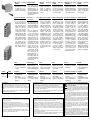
n
Mechanical mounting
(DUB02)
Hang the device to the
DIN-Rail being sure that
the spring closes. Use a
screwdriver to remove the
product as shown in figure.
o
Startup and adjustment
Check if the input range
is correct. Turn the power
ON. The green LED is ON.
Adjust the delay, upper and
lower level knobs to the
desired value. When the
voltage exceeds the upper
or drops below the lower
set point for more than the
set delay time, red LED
(flashing during the delay
time) turns ON. Relay and
yellow LED turn OFF if the
relay is normally energized,
they turn ON if normally
de-energized. Only with
relay normally de-ener
-
gized, if the voltage input
drops below 19.2 VAC the
device doesn’t ensure the
proper working of the relay.
p
Note
The packing material
should be kept for redeliv
-
ery in case of replacement
or repair.
q
Terminals
Power supply
Latch/Inhibit input
Relay output
Each terminal can accept
up to 2 x 2.5 mm
2
wires
(DUB02).
n
Montage (DUB02)
Befestigen Sie das Relais
auf der DIN-Schiene und
achten Sie darauf, daß die
Befestigungsfeder ein
-
gerastet ist. Benutzen Sie
einen Schraubenzieher, wie
im nebenstehenden Bild
gezeigt, um das Relais wie
-
der zu entfernen.
o
Einschalten und
Einstellungen
Betriebsspannung kontrol
-
lieren und einschalten - die
grüne LED leuchtet. Stellen
Sie an den Drehknöpfen die
gewünschten Grenzwerte
und die Verzögerungszeit
ein.
Wenn die Betriebsspan-
nung den eingestellten obe
-
ren oder unteren Grenzwert
länger als die vorgewählte
Verzögerungs-zeit (DIP-
Schalter SW1) über-, resp.
unterschreitet, schaltet der
Ausgang und die rote LED
leuchtet (blinkt während der
Verzögerung). Das Relais
zieht an und die gelbe LED
leuchtet, wenn mit DIP-
Schalter SW2 als “normal
deaktiviert” definiert. Bei
“normal aktiviert” fällt das
Relais ab und die gelbe
LED verlöscht. Fällt die
Betriebsspannung bei “nor
-
mal deaktiviert” unter 19.2
VAC (und nur in diesem Fall),
gewährleistet das Instrument
den korrekten Betrieb des
Relais nicht mehr.
p
Bemerkungen
Heben Sie bitte die
Originalverpackung für
eventuelle Rücksendungen
an die Serviceabteilung auf.
q
Anschlußklemmen
Betriebsspannung
Selbsthaltung/Alarmsperre
Relaisausgang
Klemmenanschluß bis max.
2 x 2,5 mm
2
je Klemme
(DUB02).
n
Montage mécanique
(DUB02)
Accrocher l’appareil sur le
rail DIN en s’assurant que
l’agrafe est positionnée.
Utiliser un tournevis pour
le retirer tel indiqué sur le
schéma.
o
Mise en service et réglage
Vérifier si la gamme de
mesure est correcte. Mettre
sous tension. La LED verte
est allumée. Ajuster le
temps, niveau haut et bas.
Quand la tension excède
ou chute au-dessous du
seuil au-delà du temps
programmé, la LED rouge
s’allume (clignotement
pendant la durée). Le relais
et la LED jaune sont activés
si le relais est normalement
désactivé, ils sont désacti
-
vés si normalement activé.
Uniquement avec un relais
normalement désactivé, si
la tension d’entrée chute
au-dessous de 19.2 VAC,
le système n’assure pas
un fonctionnement correct
du relais.
p
Note
L’emballage doit être
conservé lors du retour du
matériel en cas de rempla
-
cement ou de réparation.
q
Borniers
Alimentation
Entrée Verrouillage/inhibition
Sortie relais
Chaque borne peut accep
-
ter des câbles 2 x 2,5 mm
2
(DUB02).
n
Montaje Mecánico
(DUB02)
Sujetar el equipo al rail DIN
asegurando que las bridas
de sujección esten cerra
-
das. Use un destornillador
para manipular el equipo
como indica la figura.
o
Ajuste y puesta en marcha
Chequear que el rango
de entrada es correcto.
Alimentar el equipo, el LED
verde se enciende, ajus
-
tar los potenciometros al
valor deseado de máxima
y mínima tensión y tiempo
de retardo. Cuando la ten
-
sión sea superior o inferior
al valor ajustado, el LED
rojo parpadeará durante
el tiempo de retardo y se
pone a ON. El relé de sali
-
da y el LED amarillo se
ponen a OFF si el relé esta
normalmente excitado y se
ponen a ON si el relé esta
normalmente desexcitado.
Con relé desexcitado, si
la tensión de entrada es
menor que 19.2 VAC, el
equipo no asegura el traba
-
jo correcto del relé.
p
Nota
El embalaje deberá ser
guardado para reenviar el
equipo en caso de repara
-
ción o cambio.
q
Terminales
Alimentación
Entrada de Latch/Histéresis
Relé de salida
Cada terminal admite 2
cables de 2,5 mm
2
(DUB02)
n
Montaggio sulla guida
DIN (DUB02)
Agganciare lo strumento
alla guida DIN verificando
la chiusura della molla. Per
rimuovere il prodotto dalla
guida usare un cacciavite
come mostrato in figura.
o
Accensione e regolazione
Controllare la correttezza
della portata. Alimentare
lo strumento. Il LED verde
si accende. Regolare le
manopole di ritardo, sovra
e sottotensione al valore
desiderato. Quando l’in
-
gresso supera il livello di
sovratensione o scende al
di sotto del livello di sotto
-
tensione per più del tempo
di ritardo il LED rosso (che
lampeggia durante il tempo
di ritardo) si accende. Il relè
e il LED giallo si accendono
se il relè è normalmente
diseccitato, si spengono
se è normalmente eccitato.
Solo nel caso di relè nor
-
malmente diseccitato, se la
tesione d’ingresso scende
sotto 19.2 VAC lo strumen
-
to non assicura il corretto
funzionamento del relè.
p
Nota
Conservare l’imballo origi
-
nale in caso di sostituzione
o riparazione.
q
Terminali di collegamento
Alimentazione
Ingresso di contatto
Uscita relè
Ad ogni morsetto possono
essere collegati 2 fili di 2,5
mm
2
(DUB02)
n
Mekanisk montering
(DUB02)
Monter systemet på DIN-
skinnen, og sørg for, at fje
-
deren låser. Afmontering af
systemet foretages ved at
anvende en skruetrækker
som vist i figuren.
o
Opstart og justering
Kontroller, at indgangs
-
området er korrekt. Tilslut
forsyningsspænding. Den
grønne lysdiode tæn
-
des. Indstil knapperne
for niveau, forsinkelse og
hysterese til den ønskede
værdi. Stiger spændingen
over eller falder under den
indstillede værdi i længe
-
re tid end tidsforsinkelsen,
vil den røde lysdiode (blin
-
ker under tidsforsinkelsen)
aktiveres. Relæet og den
gule lysdiode afbrydes,
hvis relæet normalt er akti
-
veret, de aktiveres, hvis de
normalt er afbrudt.
Ved relæfunktionen normalt
afbrudt, og hvis indgangs
-
spændingen falder under
19.2 VAC, kan der ikke
garanteres korrekt funktion.
p
Bemærk
Gem emballagen til brug
ved returnering i forbindel
-
se med erstatningsleveran-
ce eller reparation.
q
Terminaler
Spændingsforsyning
Selvhold/undertrykkelse
Relæudgang
Hver terminal kan accepte
-
re kabel op til 2 x 2,5 mm
2
(DUB02)
DUB02CXXX-PUB02CXXX / code 8022096/020221 http://www.carlogavazzi.com/ CARLO GAVAZZI
DUB02 PUB02
A1, A2 2, 10
Z1, Z2 9, 8
15, 16, 18 1, 4, 3
Responsibility for disposal / Verantwortlichkeit für Entsor-
gung / Responsabilité en matière d’élimination / Respon-
sabilidad de eliminación / Responsabilità di smaltimento/
Ansvar for bortskaffelse:
The product must be disposed of at the relative recyc-
ling centres specified by the government or local public
authorities. Correct disposal and recycling will contribute
to the prevention of potentially harmful consequences to the
environment and persons.
Dieses Produkt muss bei einem geeigneten von der Regierung oder
lokalen öffentlichen Autoritäten anerkannten Recyclingbetrieb
entsorgt werden. Ordnungsgemäße Entsorgung und Recycling
tragen zur Vermeidung möglicher schädlicher Folgen für Umwelt
und Personen bei.
Éliminer selon le tri sélectif avec les structures de récupération
indiquées par l’État ou par les organismes publics locaux. Bien
éliminer et recycler aidera à prévenir des conséquences potentiel
-
lement néfastes pour l’environnement et les personnes.
Eliminar mediante recogida selectiva a través de las estructuras
de recogida indicadas por el gobierno o por los entes públicos
locales. La correcta eliminación y el reciclaje ayudarán a prevenir
consecuencias potencialmente negativas para el medioambiente
y para las personas.
Smaltire con raccolta differenziata tramite le strutture di raccolte
indicate dal governo o dagli enti pubblici locali. Il corretto smalti
-
mento e il riciclaggio aiuteranno a prevenire conseguenze poten-
zialmente negative per l’ambiente e per le persone.
Produktet skal bortskaffes på en lokal, godkendt genbrugssta
-
tion. Korrekt bortskaffelse og genbrug vil bidrage til at mindske
eventuelle skadelige konsekvenser for miljøet, mennesker og dyr.
General warnings:
- Read carefully the present instruction manual. If the device is used in a manner
not specified by the manufacturer the protection function may be impaired.
- All operations concerning installation, or unmounting, of device or modules shall
be carried out by qualified personnel and after having disconnected all power
sources.
- A readily accessible overcurrent protection (fuse or circuit breaker) shall be incor-
porated in the building installation wiring.
UL Notes:
- Use 60 or 75°C copper (CU) conductor and wire size No. 30-14 AWG, stranded
or solid (DIN models only)
- Terminal tightening torque of 4.4Lb-In” (DIN models only)
- Being these devices Overvoltage Category III they are: “For use in a circuit where
devices or system, including filters or air gaps, are used to control overvoltages at
the maximum rated impulse withstand voltage peak of 4.0 kV. Devices or system
shall be evaluated using the requirements in the Standard for Transient Voltage
Surge Suppressors, UL 1449.
- The devices shall be installed in a pollution degree 2 environment or better.
- For UL61010 compliance: The plug-in models shall be used with Carlo Gavazzi
ZPD11, ZPD11A or ZPD11XA DIN Rail Sockets.
Avertissements généraux:
- Lire attentivement ce manuel d’instructions. Si le dispositif est utilisé d’une manière autre
que celle spècifièe par le fabricant, la fonction de protection peut être altérée.
- Toutes les opérations concernant l’installation, le démontage du dispositif et des modu-
les doivent être effectuées par du personnel qualifié et uniquement après avoir déconnecté
les sources d’alimentation et de puissance.
-
Une protection contre les surintensités facilement accessible (fusible ou disjoncteur) doit
être intégrée au câblage d’installation du bâtiment.
Notes UL:
- Utilisez un conducteur en cuivre (CU) à 60 °C ou à 75 °C, calibre de fil AWG30 à AWG14
( 0.06mm
2
à 2.1mm
2
) Toronnè ou solide (modèles DIN uniquement).
- Couple de serrage des bornes de 0.5Nm (4.4Lb-In), (modèles DIN uniquement).
- S’agissant de ces dispositifs de catégorie de surtension III, ils sont: «Pour une utilisation
dans un circuit où des dispositifs ou un système, y compris des filtres ou des éclateurs,
sont utilisés pour contrôler les surtensions au maximum de la tension de tenue nominale
aux impulsions de 4.0 kV. Les appareils ou systèmes doivent être évalués conformément
aux exigences de la norme UL 1449 pour les limiteurs de surtension transitoire certifiés
pour le Canada.
- Le dispositif doit être installé dans un environnement de degré de pollution 2 (ou mieux)
et seulement par des gens qualifiés.
- Pour la conformité UL61010: les modèles enfichables doivent être installés avec des
modèles de DIN rail socle Carlo Gavazzi ZPD11, ZPD11A ou ZPD11XA.
-
 1
1
-
 2
2


CARLO GAVAZZI PUB02CT23 Guida d'installazione
- Tipo
- Guida d'installazione
- Questo manuale è adatto anche per
in altre lingue
Documenti correlati
-
CARLO GAVAZZI DUB03CW24 Guida d'installazione
-
-
-
CARLO GAVAZZI PIB01CD4850MA Guida d'installazione
-
-
CARLO GAVAZZI DUA52C748 Guida d'installazione
-
-
-
CARLO GAVAZZI DIB71CB2350MA Manuale del proprietario
-