Yamaha DSP-A1092 Manuale del proprietario
- Categoria
- Ricevitori AV
- Tipo
- Manuale del proprietario

Natural Sound AV Amplifire
Amplificateur audiovisuel “Son Naturel”
Natural Sound AV-Verstärker
Natural Sound AV-förstärkare
Amplificatore AV a suono naturale
Amplificador AV de Sonido Natural
Natural Sound AV Versterker
OWNER’S MANUAL
MODE D’EMPLOI
BEDIENUNGSANLEITUNG
BRUKSANVISNING
MANUALE DI ISTRUZIONI
MANUAL DE INSTRUCCIONES
GEBRUIKSAANWIJZING
POWER
VCR 2 DVD
/
LDVCR 1
VIDEO AUX
TAPE (MD) TV/DBS
TUNER
CD
PHONO
VOLUME
l6
20
28
40
60
l2
8
4
2
0
–dB
SPEAKERSPHONES
A
ON
OFF
B
BASS
EXTENSION
TONE
BYPASS
BASS TREBLE BALANCE
55
4
3
2
l
0
l
2
3
4
LR
55
4
3
2
l
0
l
2
3
4
55
4
3
2
l
0
l
2
3
4
VIDEO AUX
S VIDEO VIDEO L AUDIO R
DELAY
/
C
/
R
/
F
/
SWFR
EFFECT
PROGRAM
SET
MENU
NATURAL SOUND AV AMPLIFIER
DSP–A1092
CINEMA DSP
7ch
VCR 2
VIDEO AUX
REC OUT
VCR 1
TV/DBS
PHONO
CD
TUNER
DVD/LD
SOURCE
TAPE (MD)

Congratulations!
You are the proud owner of a Yamaha Digital Sound Field Processing (DSP) System—an
extremely sophisticated audio component. The DSP system takes full advantage of Yamaha’s
undisputed leadership in the field of digital audio processing to bring you a whole new world of
listening experiences. Follow the instructions in this manual carefully when setting up your system,
and the DSP system will sonically transform your room into a wide range of listening
environments—anything from a famous concert hall to a cozy jazz club. In addition, you get
incredible realism from Dolby-Surround encoded video sources using the built-in Dolby Pro Logic
Surround Decoder and Dolby Digital (AC-3) Decoder.
Seven built-in channels of amplification on this model mean that no additional amplifiers are
required to enjoy advanced digital sound field processing.
Rather than tell you about the wonders of digital sound field processing, however, let’s get right
down to the business of setting up the system and trying out its many capabilities. Please read this
operation manual carefully and store it in a safe place for later reference.

1
English
1. AVOID EXCESSIVE HEAT, HUMIDITY, DUST
AND VIBRATION
Keep the unit away from locations where it is likely to be
exposed to high temperatures or humidity—such as
near radiators, stoves, etc. Also avoid locations which
are subject to excessive dust accumulation or vibration
which could cause mechanical damage.
2. INSTALL THE UNIT IN WELL-VENTILATED
CONDITION
The openings on the cabinet assure proper ventilation
of the unit. If these openings are obstructed, the
temperature inside the cabinet will rise rapidly.
Therefore, avoid placing objects against these
openings, and install the unit in well-ventilated
condition. Make sure to allow a space of at least 10
cm behind, 20 cm on the both sides and 30 cm above
the top panel of the unit. Otherwise it may not only
damage the unit, but also cause fire.
3. KEEP THE AC POWER PLUG
DISCONNECTED DURING VACATION ETC.
When not planning to use this unit for long periods of
time (ie., vacation, etc.), disconnect the AC power
plug from the wall outlet.
4. AVOID PHYSICAL SHOCKS
Strong physical shocks to the unit can cause damage.
Handle it with care.
5. DO NOT OPEN THE UNIT OR ATTEMPT
REPAIRS OR MODIFICATIONS YOURSELF
This product contains no user-serviceable parts. Refer
all maintenance to qualified Yamaha service personnel.
Opening the unit and/or tampering with the internal
circuitry will make servicing difficult and will endanger
you and your unit.
6. MAKE SURE POWER IS OFF BEFORE
MAKING OR REMOVING CONNECTIONS
Always turn power OFF prior to connecting or
disconnecting cables. This is important to prevent
damage to the unit itself as well as other connected
equipment.
7. HANDLE CABLES CAREFULLY
Always plug and unplug cables—including the AC
cord—by gripping the connector, not the cord.
8. CLEAN WITH A SOFT DRY CLOTH
Never use solvents such as benzine or thinner to clean
the unit. Wipe clean with a soft, dry cloth.
9. USE THIS UNIT WITH THE CORRECT
VOLTAGE
The voltage to be used must be the same as that
specified on this unit. Using this unit with a higher
voltage than that which is specified is dangerous and
may result in a fire or other type of accident causing
damage. YAMAHA will not be held responsible for any
damage resulting from use of this unit with a voltage
other than that which is specified.
10.KEEP AWAY FROM TUNERS
Digital signals generated by the unit may interfere with
other equipment such as tuners, receivers or TVs. Move
the system farther away from such equipment if
interference is observed.
IMPORTANT!
Please record the model and serial number of your
unit in the space below.
Model:
Serial No.:
The serial number is located on the rear of the unit.
Retain this Owner’s Manual in a safe place for future
reference.
Voltage Selector (General Model only)
The voltage selector on the rear panel of this unit
must be set for your local mains voltage
BEFORE plugging into the AC mains supply.
Voltages are 110/120/220/240 AC, 50/60 Hz.
WARNING
To reduce the risk of fire or electric shock, do not
expose this unit to rain or moisture.
For U.K. customers
If the socket outlets in the home are not suitable for
the plug supplied with this appliance, it should be cut
off and an appropriate 3 pin plug fitted. For details,
refer to the instructions described below.
Note: The plug severed from the mains lead must be
destroyed, as a plug with bared flexible cord is
hazardous if engaged in a live socket outlet.
SPECIAL INSTRUCTIONS FOR U.K. MODEL
IMPORTANT
The wires in the mains lead are coloured in
accordance with the following code.
Blue: NEUTRAL
Brown: LIVE
As the colours of the wires in the mains lead of this
apparatus may not correspond with the coloured
markings identifying the terminals in your plug,
proceed as follows. The wire which is coloured BLUE
must be connected to the terminal which is marked
with the letter N or coloured BLACK. The wire which is
coloured BROWN must be connected to the terminal
which is marked with the letter L or coloured RED.
Making sure that neither core is connected to the
earth terminal of the three pin plug.
The apparatus is not disconnected from the AC
power source as long as it is connected to the wall
outlet, even if the apparatus itself is turned off.
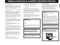
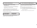
WARNING
Do not change the IMPEDANCE SELECTOR
switch setting while the power to this unit is
on, otherwise this unit may be damaged.
PRECAUTIONS & SAFETY INSTRUCTIONS
A
B
SWITCHED
AC OUTLETS
IMPEDANCE SELECTOR
VOLTAGE SELECTOR
I20W
MAX.
TOTAL
CENTER C OR D: 4
Ω
MIN./ SPEAKER
SET SPEAKER MODE
C
D: 4
Ω
MIN./ SPEAKER
SET SPEAKER MODE
REAR
4
Ω
MIN./ SPEAKER
MAIN
A
OR
B: 4
Ω
MIN./ SPEAKER
A B
: 8
Ω
MIN./ SPEAKER
FRONT EFFECT
: 6
Ω
MIN./ SPEAKER
CENTER C OR D: 8
Ω
MIN./ SPEAKER
SET SPEAKER MODE
C
D: 4
Ω
MIN./ SPEAKER
SET SPEAKER MODE
REAR
8
Ω
MIN./ SPEAKER
MAIN
A
OR
B: 8
Ω
MIN./ SPEAKER
A B
: 6
Ω
MIN./ SPEAKER
FRONT EFFECT
: 8
Ω
MIN./ SPEAKER
IMPEDANCE
SELECTOR
(General model)

PRECAUTIONS & SAFETY INSTRUCTIONS...................................1
GETTING STARTED ...........................................................................3
FEATURES ..........................................................................................5
SPEAKER SETUP.............................................................................10
CONTROLS & THEIR FUNCTIONS.................................................13
FRONT PANEL................................................................................13
DISPLAY PANEL.............................................................................16
CONNECTIONS.................................................................................17
REAR PANEL PARTS AND THEIR FUNCTIONS .........................17
REAR PANEL SWITCH AND CONTROL SETTINGS...................20
GENERAL INSTRUCTIONS FOR CONNECTIONS.....................20
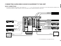
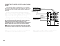
CONNECTING AUDIO/VIDEO SOURCE EQUIPMENT
TO THIS UNIT.................................................................................21
CONNECTING SPEAKER SYSTEMS...........................................25
SELECTING THE OUTPUT MODES SUITABLE FOR YOUR
SPEAKER SYSTEM .......................................................................30
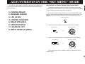
SPEAKER BALANCE ADJUSTMENT ............................................33
ADJUSTMENTS IN THE “SET MENU” MODE...............................35
GENERAL OPERATION...................................................................38
PLAYING A SOURCE.....................................................................38
RECORDING A SOURCE TO AUDIO/VIDEO TAPE
(OR DUBBING FROM A TAPE TO ANOTHER) ............................40
SELECTING SOUND FIELD PROGRAMS......................................42
CANCELING THE EFFECT SOUND.............................................43
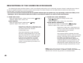
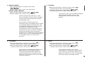
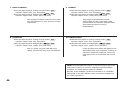
DESCRIPTIONS OF THE SOUND FIELD PROGRAMS..............44
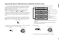
ADJUSTING DELAY TIME AND EACH SPEAKER OUTPUT
LEVEL..............................................................................................47
SETTING THE SLEEP TIMER..........................................................49
REMOTE CONTROL UNIT ...............................................................50
BASIC OPERATIONS (When the lid is open) ................................50
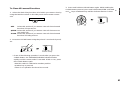
LEARNING NEW CONTROL FUNCTIONS (When the lid is open)
.........................................................................................................52
USING OPERATION CONTROL KEYS (When the lid is closed)
.........................................................................................................55
MACRO OPERATIONS (When the lid is closed) ...........................58
LEARNING A NEW FUNCTION.....................................................61
MAKING A NEW MACRO...............................................................63
CLEARING LEARNED FUNCTIONS.............................................64
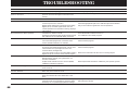
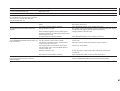
TROUBLESHOOTING ......................................................................66
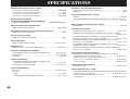
SPECIFICATIONS .............................................................................68
2
CONTENTS

3
English
GETTING STARTED
Unpacking
If you haven’t already done so, carefully remove this unit and its
accessories from the box and wrapping material. You should find the
unit itself and the following accessories.
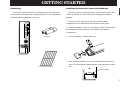
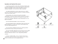
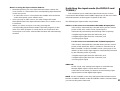
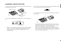
Installing the Remote Control Unit Batteries
Since the remote control unit will be used for many of this unit’s
control operations, you should begin by installing the supplied
batteries.
1. Turn the remote control unit over and slide the battery
compartment cover downward in the direction of the arrow.
2. Insert the batteries (LR6, AA, UM-3 type), being careful to align
them with the polarity markings on the inside of the battery
compartment.
3. Close the battery compartment cover.
* After you insert batteries (or you exchange batteries with new
ones), press the RESET button before using the remote control
unit.
Remote control
User function stickers
Batteries
1
3
2
RESET button

4
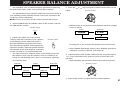
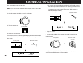
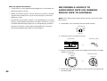
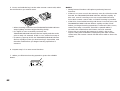
Notes about the Remote Control Unit
● When you notice that remote control operation has become
erratic, or the distance from which the remote control will function
has decreased, it’s time to replace the batteries. Always replace all
batteries at the same time.
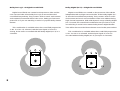
● This remote control uses an advanced, highly directional infrared
beam. Be sure to aim the remote control directly at the remote
control sensor on the main unit when operating.
Remote control transmitter operation range
Notes
●
There should be no large obstacles between the remote control
unit and the main unit.
●
If the remote control sensor is directly illuminated by strong
lighting (especially an inverter type of fluorescent lamp etc.), it
might cause the remote control unit to work incorrectly. In this
case, reposition the main unit to avoid direct lighting.
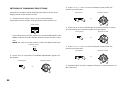
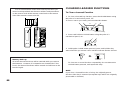
Open/close the control door
When it is not necessary to operate controls inside the control
door, close the door.
To open the door
To close the door
30°
30°
Remote control
sensor
Within approximately
6 m (19.7 feet)

5
English
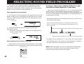
This unit incorporates a sophisticated, multi-program digital
sound field processor. The processor allows you to electronically
expand and change the shape of the audio sound field from both
audio and video sources, creating a theater-like experience in your
listening room. This unit has a total of 10 digital sound field
processor (DSP) modes. You can create an excellent audio sound
field by selecting a suitable sound field (this will, of course, depend
on what you will be listening to), and adding desired adjustments.
In addition, this unit incorporates a Dolby Pro Logic Surround
decoder and Dolby Digital (AC-3) decoder for multi-channel sound
reproduction of Dolby Surround encoded video sources. The
operation of the Dolby Pro Logic Surround or Dolby Digital (AC-3)
decoder can be controlled by selecting a corresponding DSP
program including combined operations of the Yamaha DSP and
the Dolby Pro Logic Surround or Dolby Digital (AC-3) decoder.
Digital Sound Field Processing
What is it that makes live music so good? Today’s advanced
sound reproduction technology lets you get extremely close to the
sound of a live performance, but chances are you’ll still notice
something missing, the acoustic environment of the live concert
hall. Extensive research into the exact nature of the sonic
reflections that create the ambience of a large hall has made it
possible for Yamaha engineers to bring you this same sound in
your own listening room, so you’ll feel all the sound of a live
concert. What’s more, our technicians, armed with sophisticated
measuring equipment, have even made it possible to capture the
acoustics of a variety of actual concert halls, jazz clubs, theaters,
etc. from around the world, to allow you to accurately recreate any
one of these live performance environments, all in your own home.
FEATURES

6
Dolby Pro Logic Surround
This unit employs a Dolby Pro Logic Surround decoder similar
to professional Dolby Stereo decoders used in many movie
theaters. By using the Dolby Pro Logic Surround decoder, you can
experience the dramatic realism and impact of Dolby Surround
movie theater sound in your own home. Dolby Pro Logic employs a
four channel five speaker system. The Pro Logic Surround system
divides the input signal into four levels: the left and right main
channels, the center channel (used for dialog), and the rear
surround sound channels (used for sound effects, background
noise, and other ambient noises). The center channel allows
listeners seated in even less-than-ideal positions to hear the dialog
originating from the action on the screen while experiencing good
stereo imaging. Dolby Surround is encoded on the sound track of
pre-recorded video tapes, laser discs, and some TV/cable
broadcasts. When you play a source encoded with Dolby Surround
on this unit, the Dolby Pro Logic Surround decoder decodes the
signal and distributes the surround-sound effects.
This Dolby Pro Logic Surround Decoder employs a digital
signal processing system. This system improves the stability of
sound at each channel and crosstalk between channels, so that
positioning of sounds around the room is more accurate compared
with conventional analog signal processing systems.
In addition, this unit features a built-in automatic input balance
control. This always assures you the best performance without
manual adjustment.
Dolby Digital (AC-3)
The built-in Dolby Digital (AC-3) Decoder leads you into a
totally new sound experiences.
Dolby Digital (AC-3) is a new generation of multi-channel digital
audio technology, or the newest spatial sound processing format
developed for 35 mm film-movies by employing a new kind of low
bit-rate audio coding.
Dolby Digital (AC-3) is a digital surround sound system that
provides completely independent multi-channel audio to
consumers. In multi-channel form, Dolby Digital (AC-3) provides
five full range channels in what is sometimes referred to as a “3/2”
configuration: three front channels (left, center and right), plus two
surround channels. A sixth bass-only effect channel is also
provided for output of LFE (low frequency effect), or low bass
effects that are independent of other channels. This channel is
counted as 0.1, thus giving rise to the term 5.1 channels in total.
Compared to Dolby Pro Logic that is referred to a “3/1” system
(left front, center, right front and just one surround channel), Dolby
Digital (AC-3) features two surround channels, called stereo or
split surrounds, each offering the same full range fidelity as the
three front channels.
Sound of wide dynamic range reproduced by the five full range
channels presents listeners much excitement that has never been
experienced before. Precise sound orientation by the discrete
digital sound processing expands realism that the original movie
possesses.

7
English
Laser Disc is a home audio format that could benefit from
Dolby Digital (AC-3). In the near future, Dolby Digital (AC-3) will
also be applied to DBS, CATV, DVD and HDTV. The ongoing
release of Dolby Stereo Digital theatrical films now underway will
provide an immediate source of Dolby Digital (AC-3) encoded
video software.
Manufactured under license from Dolby Laboratories Licensing
Corporation. “Dolby”, “AC-3”, “Pro Logic”, and the double-D symbol
are trademarks of Dolby Laboratories Licensing Corporation.
Copyright 1992 Dolby Laboratories, Inc. All rights reserved.
The following original functions make the surround-sound effect
of Dolby Digital (AC-3) become the most suitable for your audio
system and the listening conditions.
● Dynamic range (sound scale) of source can be changed so
that it will be suitable for the listening conditions.
● Output of low bass from any channel can be assigned to
either the MAIN SPEAKERS terminals or SUBWOOFER
terminals to maximize system performance.
● Output of LFE can be assigned to either the MAIN
SPEAKERS terminals or SUBWOOFER terminals to
maximize system performance.
Dolby Surround + DSP (CINEMA DSP)
Dolby Surround sound system shows its full ability in a large
movie theater, because movie sounds are originally designed to be
reproduced in a large movie theater using many speakers. It is
difficult to create a sound environment similar to that of a movie
theater in your listening room, because the room size, materials of
inside walls, the number of speakers, etc. of your listening room is
much different from those of a movie theater.
Yamaha DSP technology made it possible to present you with
nearly the same sound experience as that of a large movie theater
in your listening room by compensating for lack of presence and
dynamics in your listening room with its original digital sound fields
combined with Dolby Surround sound field.
The YAMAHA “CINEMA DSP” logo indicates those programs
are created by the combination of Dolby Surround and YAMAHA
DSP technology.
CINEMA DSP
7ch

8
Dolby Pro Logic + 2 Digital Sound Fields
Digital sound fields are created on the presence side and the
rear surround side of the Dolby Pro Logic Surround-decoded
sound field respectively. They create a wide acoustic environment
and emphasize surround-effect in the room, letting you feel much
presence as if you are watching a movie in a popular Dolby Stereo
theater.
This combination is available when the sound field program No.
2, No. 3 or No. 4 is selected, and the input signal of source is
analog, PCM audio or encoded with the Dolby Digital (AC-3) in 2-
channels.
Dolby Digital (AC-3) + 3 Digital Sound Fields
Digital sound fields are created on the presence side and the
independent left and right surround sides of the Dolby Digital (AC-
3)-decoded sound field respectively. They create a wide acoustic
environment and much surround effect in the room without losing
high channel separation. With wide dynamic range of Dolby Digital
(AC-3) sound, this sound field combination lets you feel as if you
are watching a movie in the newest Dolby Stereo Digital theater.
This will be the most ideal home theater sound at the present time.
This combination is available when the sound field program No.
2, No. 3 or No. 4 is selected, and the input signal of source is
encoded with the Dolby Digital (AC-3) (except in 2-channels).

9
English
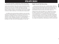
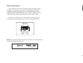
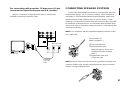
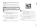
Video superimpose
If you connect your video cassette recorder, LD player, video
monitor, etc. to this unit, you can take advantage of this unit’s
capability to display program titles and information for various
setting changes and adjustments on your video monitor’s screen.
This information will be superimposed over the video image.
If there is no video source connected or it is turned off, the
information will be displayed over a blue colored background.
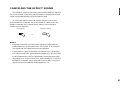
NOTE: The program titles and other information are also displayed
on the display panel of this unit.
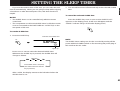
TEST DSP
EFFECT LEVEL
FRONT 0dB
/
SPEAKERS
A
DSP

10
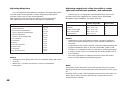
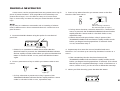
Setting Up Your Speaker System
This unit has been designed to provide the best sound field
quality with a full seven-speaker system setup, using two extra
pairs of effect speakers to generate the sound field plus one center
speaker for dialog. We therefore recommend that you use a seven-
speaker setup. A four-speaker system using only one pair of effect
speakers for the sound field will still provide impressive ambience
and effects, however, and may be a good way to begin with this
unit. You can always upgrade to the full seven speaker system
later. In the 4 or 5 speaker system, the Digital Sound Field
Processing is still performed, but the main speakers are used for
both the main channels and the front effect channels.
Use of the Center Dialog Speaker Is Recommended
When playing back a source with the DSP programs No. 1
through No. 4, or when the Dolby Digital (AC-3) is decoded with
any DSP program used, if the source contains center-channel
signals, dialog, vocals etc. are output from the center channel.
Therefore, if you want to maximize the performance of your
Audio/Video home theater system, it is recommended that you use
a center channel speaker.
If for some reason it is not practical to use a center speaker, it
is possible to enjoy movie viewing without it. Best results, however,
are obtained with the full system.
Use of a Subwoofer Expands Your Sound Field
It is also possible to further expand your system with the
addition of a subwoofer and amplifier. The use of a subwoofer is
effective not only for reinforcing bass frequencies from any or all
channels, but also for reproducing the LFE (low frequency effect)
sound with high fidelity when playing back a source with the Dolby
Digital (AC-3) decoded. You may wish to choose the convenience
of a Yamaha Active Servo Processing Subwoofer System, which
has its own built-in power amplifier.
SPEAKER SETUP

11
English
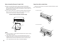
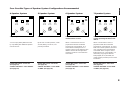
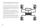
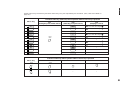
4 Speaker System
Simplest system.
You can enjoy widely diffused sound
by only adding two additional speaker
units at the rear.
FRONT MIX switch—Set to ON.
(See page 20.)
CENTER SPEAKER—Set to PHNTM.
(See page 30.)
5 Speaker System
Good for Audio/Video sources.
By the use of center speaker, center
sounds (dialog, vocals etc.) are
precisely localized.
FRONT MIX switch—Set to ON.
(See page 20.)
CENTER SPEAKER—Set to NRML
or WIDE. (See page 30.)
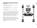
6 Speaker System
Good for sound fields from 2-
channel stereo sources.
When a normal stereo source is
played back with the sound field
programs No. 5 through No. 10, a
sound effect matching that of a 7-
speaker system can be obtained. The
addition of front left and right effect
speakers produces a more effective
sound field.
FRONT MIX switch—Set to OFF.
(See page 20.)
CENTER SPEAKER—Set to PHNTM.
(See page 30.)
7 Speaker System
This is the recommended speaker
system, providing the best sound
effects.
When a normal stereo source is
played back with the sound field
programs No. 5 through No. 10, using
both sets of effect speakers (front and
rear), reproduces the most effective
sound field. When using the sound
field programs No. 1 through No. 4 or
when using any program with the
Dolby Digital (AC-3) decoded, the
center speaker provides precise center
localization.
FRONT MIX switch—Set to OFF.
(See page 20.)
CENTER SPEAKER—Set to NRML
or WIDE. (See page 30.)
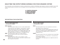
Four Possible Types of Speaker System Configurations Recommended

12
Speakers and Speaker Placement
Your full seven-speaker system will require three speaker pairs:
the MAIN SPEAKERS (your normal stereo speakers), the FRONT
EFFECT SPEAKERS and the REAR SPEAKERS, plus the
CENTER SPEAKER. You may also be using a subwoofer.
The MAIN SPEAKERS should be high performance models
and have enough power handling capacity to accept the maximum
output of your audio system.
Other speakers do not have to be equal to the MAIN
SPEAKERS. For precise sound localization, however, it is ideal to
use high performance models that can reproduce sounds in full
range for the CENTER SPEAKER and the FRONT EFFECT and
REAR SPEAKERS.
Place the MAIN SPEAKERS in the normal position.
Place the FRONT EFFECT SPEAKERS further apart than the
MAIN SPEAKERS, on either side of and a few feet behind and
above the MAIN SPEAKER pair.
Place the REAR SPEAKERS behind your listening position.
They should be nearly six feet up from the floor.
Place the CENTER SPEAKER precisely between the two MAIN
SPEAKERS. (To avoid interference, keep the speaker above or
below the television monitor, or use a magnetically shielded
speaker.)
If using a SUBWOOFER, such as a Yamaha Active Servo
Subwoofer System, the position of the speaker is not so critical
because low bass tones are not highly directional.
Main speaker
Front effect speaker
Center speaker
Rear speaker
Subwoofer

13
English
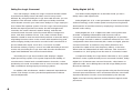
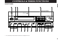
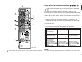
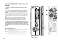
FRONT PANEL
CONTROLS & THEIR FUNCTIONS
POWER
VCR 2 DVD
/
LDVCR 1
VIDEO AUX
TAPE (MD) TV/DBS
TUNER
CD
PHONO
VOLUME
l6
20
28
40
60
l2
8
4
2
0
–dB
SPEAKERSPHONES
A
ON
OFF
B
BASS
EXTENSION
TONE
BYPASS
BASS TREBLE BALANCE
55
4
3
2
l
0
l
2
3
4
LR
55
4
3
2
l
0
l
2
3
4
55
4
3
2
l
0
l
2
3
4
VIDEO AUX
S VIDEO VIDEO L AUDIO R
DELAY
/
C
/
R
/
F
/
SWFR
SET
MENU
EFFECTPROGRAM
NATURAL SOUND AV AMPLIFIER
DSP–A1092
CINEMA DSP
7ch
VCR 2
VIDEO AUX
REC OUT
VCR 1
TV/DBS
PHONO
CD
TUNER
DVD/LD
SOURCE
TAPE (MD)
1 456
JIHGF
EDCBA0987
23
(Europe Model)
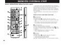
* For control keys on the remote control unit, see pages 50 to 52.

14
1 POWER Switch
Turns this unit on and off.
* When you press this switch to turn the power on, you will hear
a click and a sound of the built-in fan rotating for a moment.
2 Standby Indicator
While the power of this unit is on, pressing the (SYSTEM
POWER) OFF key on the remote control unit switches this unit
to the standby mode. In this mode, the standby indicator is
illuminated.
3 Remote Control Sensor
Signals from the remote control unit are received here.
4 Display Panel
See page 16.
5 Input Selector Buttons
Selects an input source that you want to listen to (and watch).
6 Master VOLUME Control
Simultaneously controls volume level at all outputs: front effect,
main, rear effect, center, and subwoofer. (This does not affect
REC OUT level.)
* When the volume is decreased by pressing the MUTE key on
the remote control unit, the indicator on the master VOLUME
control flashes on and off.
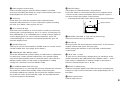
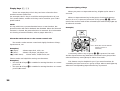
7 PHONES Jack
When you listen with headphones, connect the headphones to
the PHONES jack. You can listen to the sound to be output
from the main speakers through headphones.
When listening with headphones privately, set both the
SPEAKERS A and B switches to the OFF position and switch
off the digital sound field processor (so that no DSP program
name is illuminated on the display panel) by pressing the
EFFECT switch.
8 SPEAKERS switches
Set the switch A or B (or both A and B) for the main speakers
(connected to this unit) you will use to the ON position. Set the
switch for the main speakers you will not use to the OFF
position. Selected main speakers are shown by the lighting of
“SPEAKERS A” and/or “SPEAKERS B” on the display panel.
9 BASS EXTENSION Switch
When pressed inward (ON), boosts bass frequency response
at the main left and right channels while maintaining overall
tonal balance. If you do not have a subwoofer, the use of this
switch will be effective to reinforce the bass frequencies.
0 TONE BYPASS switch
When this switch is pressed inward (ON), the input signal does
not pass through the tone (BASS and TREBLE) control circuitry
so that it is unaffected by the tone control circuitry. Use this
switch to obtain pure sound and to check the tone control
setting. Press this switch to release it outward (OFF) to use the
tone control circuitry.
A BASS and TREBLE Controls
Adjust low and high frequency response respectively for the
main channels only.
B BALANCE Control
Adjusts the left and right output volume to the Main Speakers to
compensate for sound imbalance caused by speaker positions
or listening room conditions.
C REC OUT Selector
Selects the source to be recorded to a tape deck or
VCR independently of the setting of the input selector buttons.
However, when set to the SOURCE position, the setting of the
input selector buttons decides the source to be recorded to a
tape deck or VCR.

15
English
D PROGRAM Selector
Sequentially selects the digital sound field processing programs
in the + or – direction.
E SET MENU Switch
Whenever pressed, selects functions in the SET MENU mode.
F DELAY/C/R/F/SWFR Switch
Whenever pressed, selects the item of changing delay time,
center speaker output level, rear speaker output level, front
effect speaker output level and subwoofer output level in turn.
* Depending on a mode of this unit, the number of selections is
reduced. For example, when the built-in digital sound field
processor (including the Dolby Pro Logic Decoder or the
Dolby Digital (AC-3) Decoder) is off, only the item for
changing subwoofer output level can be selected.
G –/+ Button
Adjusts the level of item selected by pressing the
DELAY/C/R/F/SWFR switch. Moreover, performs setting
changes and adjustments for functions selected by pressing
the SET MENU switch.
H EFFECT Switch
Normally ON, this switch can be turned OFF to disable output
from the center and effect speakers so that the sound becomes
normal 2-channels.
* Even if this switch is off, when the Dolby Digital (AC-3) is
decoded, signals at all channels are distributed to the main
channels and output from the main speakers.
I Auxiliary Input Jacks (VIDEO AUX)
Connect an auxiliary video or audio unit such as a camcorder
to these jacks. If the connected video unit has a S video output
terminal, connect it to the S VIDEO jack to obtain a high
resolution picture. The unit connected to these jacks can be
selected by the corresponding input selector button and REC
OUT selector.
J Control Door
See page 4 for how to open and close the control door.

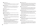
16
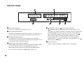
1 Input Source Display
Shows the currently selected input source.
2 Multi-informatiom Display
Shows the currently selected DSP program, or information for
several adjustments or setting changes made on this unit.
3 SPEAKERS A/B Indicators
The indicator A or B which corresponds to the currently
selected main speakers lights up. If both main speakers A or B
are selected, both indicators light up.
4 Digital Audio Input Signal Indicators
When digital audio signals not encoded with the Dolby Digital
(AC-3) are input to this unit, “PCM DIGITAL” lights up.
When digital audio signals encoded with the Dolby Digital
(AC-3) are input to this unit, “ DIGITAL” lights up.
5 DIGITAL, DSP and PRO LOGIC indicators
“ DIGITAL” lights up when the built-in Dolby Digital (AC-3)
Decoder is on and the signals of selected source encoded with
the Dolby Digital (AC-3) is not in 2-channels. “DSP” lights up
when the built-in digital sound field processor is on, and “
PRO LOGIC” lights up when the built-in Dolby Pro Logic
Surround Decoder is on. Depending on the selected DSP
program, both “ DIGITAL” and “DSP”, or both “DSP” and “
PRO LOGIC” will light up.
6 SLEEP Indicator
Lights up while the built-in SLEEP timer is functioning.
DISPLAY PANEL
DIGITAL
ENHANCED
SPEAKERS
A
SPEAKERS
B
PCM
DIGITAL
70
mm
DIGITAL
SLEEP
mS dB
DSP
PRO LOGIC
3 4 5 6
1 2

17
English
PHONO
VIDEO
DVD/LD
TV/DBS
IN
VCR 1
OUT
IN
VCR 2
OUT
DVD/LD
TV/DBS
CENTER
C OR D
C D
SEE INSTRUCTION MANUAL FOR CORRECT
SETTING.
CENTER
CAUTION
IN
VCR 1
OUT
IN
VCR 2
OUT
MONITOR
OUT
MAIN CH SUB
WOOFER
FRONT
EFFECT
REAR
PRE
OUT
MAIN
IN
S VIDEO
1
CD
2
TUNER
3
TAPE
PB
AUDIO SIGNAL
GND
AUDIO SIGNAL VIDEO SIGNAL OUTPUT SPEAKERS
COUPLER OUTPUT
5ch 7ch
ON OFF
PAL NTSC
MONITOR
OUT
FRONT
MIX
—
I0dB 0dB
MAIN
LEVEL
CC
D
A
B
A
B
D
REAR
FRONT
EFFECT
MAIN
SWITCHED
AC OUTLETS
IMPEDANCE SELECTOR
VOLTAGE SELECTOR
I00W
MAX.
TOTAL
PCM/
DIGITAL IN
4
REC
OUT
TAPE(MD)
DVD/LD
OPTICAL
COAXIAL
OPTICAL
(AC-3 DIGITAL IN)
TV/DBS
COAXIAL
CENTER C OR D: 4
Ω
MIN./ SPEAKER
SET SPEAKER MODE
C
D: 4
Ω
MIN./ SPEAKER
SET SPEAKER MODE
REAR
4
Ω
MIN./ SPEAKER
MAIN
A
OR
B: 4
Ω
MIN./ SPEAKER
A B
: 8
Ω
MIN./ SPEAKER
FRONT EFFECT
: 6
Ω
MIN./ SPEAKER
CENTER C OR D: 8
Ω
MIN./ SPEAKER
SET SPEAKER MODE
C
D: 4
Ω
MIN./ SPEAKER
SET SPEAKER MODE
REAR
8
Ω
MIN./ SPEAKER
MAIN
A
OR
B: 8
Ω
MIN./ SPEAKER
A B
: 6
Ω
MIN./ SPEAKER
FRONT EFFECT
: 8
Ω
MIN./ SPEAKER
0ABCDEFIJ KHG
12 3 4 56 7 89
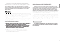
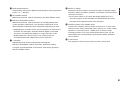
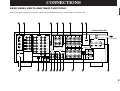
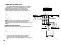
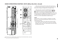
REAR PANEL PARTS AND THEIR FUNCTIONS
Before you start making connections make sure all related electronic components are turned OFF.
CONNECTIONS
(General Model)
To AC outlet

18
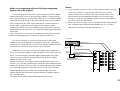
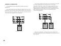
1 PCM/ DIGITAL IN (COAXIAL and OPTICAL) jacks
Can be connected with audio/video units that have a coaxial or
optical digital output jack. Connect a unit that is connected to
the DVD/LD AUDIO/VIDEO SIGNAL connection jacks to the
DVD/LD COAXIAL or OPTICAL jack.
Connect a unit that is connected to the TV/DBS AUDIO/VIDEO
SIGNAL connection jacks to the TV/DBS COAXIAL or
OPTICAL jack.
* If, for example, your LD player has an AC-3 RF output jack
and no digital output jack for AC-3 discrete audio signals,
connect the AC-3 RF output jack to the DVD/LD COAXIAL or
OPTICAL jack of this unit by way of an RF demodulator
(separate purchase).
2 AUDIO SIGNAL Connection Jacks (for Audio Source
Equipment)
Connect the inputs and/or outputs of your audio equipment.
3 AUDIO/VIDEO SIGNAL Connection Jacks (for Video Source
Equipment)
Connect the audio and video inputs and/or outputs of your
video equipment. In place of the VIDEO jacks, the S VIDEO
jacks can be used for higher resolution and improved picture
quality if your VCR, monitor, etc. are equipped with S-VIDEO
connectors.
4 CENTER OUTPUT Jacks
Center-channel line outputs. Can be connected to input jack(s)
of one or two external power amplifier(s) to drive the center
speaker(s).
5 CENTER SPEAKERS Terminals
When using the built-in center-channel amplifier, connect one
or two center speakers here.
6 Center Speaker Switch
Set to “C + D” when using two center speakers, or to “C OR D”
when using only one center speaker.
7 FRONT EFFECT SPEAKERS Terminals
When using the built-in front effect-channel amplifier, connect
the front effect speakers here.
8 REAR SPEAKERS Terminals
When using the built-in rear-channel amplifier, connect the rear
speakers here.
9 VOLTAGE SELECTOR (General Model only)
Be sure to set to the line voltage in your area before applying
power. Consult your dealer if unsure of the correct setting.
0 GND Terminal
Connects the ground wire of the turntable to produce minimum
hum. In some cases, however, better results may be obtained
with the ground wire disconnected.
A Video NTSC/PAL Switch (General Model only)
Set this switch to the position corresponding to the standard
that your video equipment employs.
B FRONT MIX Switch
Set to “OFF (7ch)” when setting up a full 7 or 6 speaker
system, or to “ON (5ch)” when setting up a 5 or 4 speaker
system.
C MAIN LEVEL Switch
Normally set to “0 dB”. If desired, you can decrease the main-
channel output level at the MAIN SPEAKERS terminals by 10
dB by setting this switch to “–10 dB”.
La pagina si sta caricando...
La pagina si sta caricando...
La pagina si sta caricando...
La pagina si sta caricando...
La pagina si sta caricando...
La pagina si sta caricando...
La pagina si sta caricando...
La pagina si sta caricando...
La pagina si sta caricando...
La pagina si sta caricando...
La pagina si sta caricando...
La pagina si sta caricando...
La pagina si sta caricando...
La pagina si sta caricando...
La pagina si sta caricando...
La pagina si sta caricando...
La pagina si sta caricando...
La pagina si sta caricando...
La pagina si sta caricando...
La pagina si sta caricando...
La pagina si sta caricando...
La pagina si sta caricando...
La pagina si sta caricando...
La pagina si sta caricando...
La pagina si sta caricando...
La pagina si sta caricando...
La pagina si sta caricando...
La pagina si sta caricando...
La pagina si sta caricando...
La pagina si sta caricando...
La pagina si sta caricando...
La pagina si sta caricando...
La pagina si sta caricando...
La pagina si sta caricando...
La pagina si sta caricando...
La pagina si sta caricando...
La pagina si sta caricando...
La pagina si sta caricando...
La pagina si sta caricando...
La pagina si sta caricando...
La pagina si sta caricando...
La pagina si sta caricando...
La pagina si sta caricando...
La pagina si sta caricando...
La pagina si sta caricando...
La pagina si sta caricando...
La pagina si sta caricando...
La pagina si sta caricando...
La pagina si sta caricando...
La pagina si sta caricando...
La pagina si sta caricando...
-
 1
1
-
 2
2
-
 3
3
-
 4
4
-
 5
5
-
 6
6
-
 7
7
-
 8
8
-
 9
9
-
 10
10
-
 11
11
-
 12
12
-
 13
13
-
 14
14
-
 15
15
-
 16
16
-
 17
17
-
 18
18
-
 19
19
-
 20
20
-
 21
21
-
 22
22
-
 23
23
-
 24
24
-
 25
25
-
 26
26
-
 27
27
-
 28
28
-
 29
29
-
 30
30
-
 31
31
-
 32
32
-
 33
33
-
 34
34
-
 35
35
-
 36
36
-
 37
37
-
 38
38
-
 39
39
-
 40
40
-
 41
41
-
 42
42
-
 43
43
-
 44
44
-
 45
45
-
 46
46
-
 47
47
-
 48
48
-
 49
49
-
 50
50
-
 51
51
-
 52
52
-
 53
53
-
 54
54
-
 55
55
-
 56
56
-
 57
57
-
 58
58
-
 59
59
-
 60
60
-
 61
61
-
 62
62
-
 63
63
-
 64
64
-
 65
65
-
 66
66
-
 67
67
-
 68
68
-
 69
69
-
 70
70
-
 71
71


Yamaha DSP-A1092 Manuale del proprietario
- Categoria
- Ricevitori AV
- Tipo
- Manuale del proprietario
in altre lingue
- English: Yamaha DSP-A1092 Owner's manual
- français: Yamaha DSP-A1092 Le manuel du propriétaire
- español: Yamaha DSP-A1092 El manual del propietario
- Deutsch: Yamaha DSP-A1092 Bedienungsanleitung
- русский: Yamaha DSP-A1092 Инструкция по применению
- Nederlands: Yamaha DSP-A1092 de handleiding
- português: Yamaha DSP-A1092 Manual do proprietário
- dansk: Yamaha DSP-A1092 Brugervejledning
- čeština: Yamaha DSP-A1092 Návod k obsluze
- polski: Yamaha DSP-A1092 Instrukcja obsługi
- svenska: Yamaha DSP-A1092 Bruksanvisning
- Türkçe: Yamaha DSP-A1092 El kitabı
- suomi: Yamaha DSP-A1092 Omistajan opas
- română: Yamaha DSP-A1092 Manualul proprietarului
Documenti correlati
-
Yamaha DSP -A780 Manuale utente
-
-
-
-
-
-
Yamaha DSP-A1 Manuale utente
-
-
-
