La pagina si sta caricando...

ISTRUZIONI PER L’INSTALLATORE
INSTRUCTIONS FOR THE INSTALLER
ANLEITUNGEN FÜR DEN INSTALLATEUR
NOTICE POUR L'INSTALLATEUR
INSTRUCCIONES PARA EL INSTALADOR
SIMPLE Convection with humidification models 5 x 2/3 GN / 5-10 x 1/1 GN / 5 x (60x40)
1
INDICE
INDEX
INHALTSVERZEICHNIS
INDEX
INDICE
Dichiarazione di conformità Konformitätserklärung Declaración de conformidad
1.0
Conformity of declaration Déclaration de conformité
Direttiva europea 2002/96/ec Europäischen richtlinie 2002/96/eg Directiva 2002/96/ec
1.1
European directive 2002/96/ec Directive européenne 2002/96/ce Europese richtlijn 2002/96/eg
Dimensioni Abmessungen Medidas
1.3A/B
Dimensions Dimensions
5 x 2/3 GN
5 x 1/1 GN
Dimensioni Abmessungen Medidas
1.3C/D
Dimensions Dimensions
10 x 1/1GN
5 x (60x40)
Tabella dati allacciamento elettrico Technische Daten für Elektroanschluss Tabla datos técnicos de conexión eléctrica
1.6
Technical data for electrical connection Tableau des données techniques raccordem. Electrique
1.8
1.9
Installazione dell’apparecchio Geräteinstallation Instalación del aparato
2.0
Appliance installation Installation de l’appareil
2.1
Collegamento elettrico Elektroanschluss Conexión eléctrica
2.2
Electrical connection Raccordement électrique
Collegamento idraulico entrata acqua Anschluss an das Wassernetz – Wasserzufuhr Conexión hídrica-entrada del agua
2.3
Hydraulic connection – water inlet Raccordement hydraulique - arrivée d'eau
Collegamento idraulico scarico acqua Anschluss an das Wassernetz – Wasserablauf Conexión hídrica – desagüe
2.4
Hydraulic connection- water drainage Raccordement hydraulique -vidange d'eau
2.5
2.6
2.7
2.8
Automatismi di controllo e sicurezza Kontroll- und Sicherheitsautomatismen Automatismos de control de seguridad
3.0
Control and safety devices Organes de contrôle et de sécurité
Sostituzione parti di ricambio Austausch der Ersatzteile Piezas de repuesto
3.1
Spare parts replacing Remplacement des pièces
1.0 DICHIARAZIONE DI CONFORMITA
Il Costruttore dichiara che gli apparecchi sono conformi alle prescrizioni CEE.
L’installazione dovrà essere effettuata in osservanza alle norme vigenti, soprattutto in merito all’areazione dei locali e dei sistemi per l’evacuazione dei
gas combusti.
N.B.: Il Costruttore declina ogni responsabilità in caso di danni diretti derivati da: uso non corretto, errata installazione e da cattiva
manutenzione.
1.0 CONFORMITY OF DECLARATION
The Manufacturer declares that the appliances conform to the EEC norms.
They must be installed in accordance with current standards, especially regarding aeration of the premises and the exhaust gas evacuation system.
Note: The Manufacturer declines all and every responsibility for any direct damages caused by: an incorrect use, wrong installation or
bad maintenance.
1.0 KONFORMITÄTSERKLÄRUNG
Der Hersteller bestätigt, dass die Geräte den EU-Vorschriften entsprechen.
Die Installation muss, insbesondere bezüglich der Belüftung der Räume und der Abgasleitung, gemäß den gültigen Normen durchgeführt werden.
Achtung: Der Hersteller haftet nicht für direkte Schäden, die durch unsachgemäße Bedienung, falsche Installation, oder mangelnde
Wartung verursacht worden sind.
1.0 DÉCLARATION DE CONFORMITÉ
Le constructeur déclare que les appareils sont conformes aux normes CEE.
L’installation devra être effectuée en respectant les normes en vigueur, notamment celles concernant l’aération des locaux.
Attention: Le
constructeur décline toute responsabilité en cas de dommages dérivant d’une utilisation incorrecte, d’une installation
erronée et d’une mauvaise maintenance.
1.0 DECLARACIÓN DE CONFORMIDAD
El fabricante declara que los aparatos son conformes a las prescripciones CEE.
La instalación debe ser efectuada según las normas vigentes, sobre todo en cuanto a la ventilación de los locales.
Attención: El Fabricante rehusa cualquier responsabilidad en caso de daños directos causados por: uso no correcto, instalación errada y
falta de mantenimiento.

ISTRUZIONI PER L’INSTALLATORE
INSTRUCTIONS FOR THE INSTALLER
ANLEITUNGEN FÜR DEN INSTALLATEUR
NOTICE POUR L'INSTALLATEUR
INSTRUCCIONES PARA EL INSTALADOR
SIMPLE Convection with humidification models 5 x 2/3 GN / 5-10 x 1/1 GN / 5 x (60x40)
2
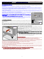
1.1 DIRETTIVA EUROPEA 2002/96/EC
Questo apparecchio è contrassegnato in conformità alla Direttiva Europea 2002/96/EC, Waste Electrical and Electronic Equipment (WEEE).
Assicurandosi che questo prodotto sia smaltito in modo corretto, l'utente contribuisce a prevenire le potenziali conseguenze negative per l'ambiente e la
salute.
Il simbolo
sul prodotto o sulla documentazione di accompagnamento indica che questo prodotto non deve essere trattato come rifiuto domestico ma
deve essere consegnato presso l'idoneo punto di raccolta per il riciclaggio di apparecchiature elettriche ed elettroniche.
Disfarsene seguendo le normative locali per lo smaltimento dei rifiuti.
Per ulteriori informazioni sul trattamento, recupero e riciclaggio di questo prodotto, contattare l'idoneo ufficio locale, il servizio di raccolta dei rifiuti
domestici o il negozio presso il quale il prodotto è stato acquistato.
1.1 EUROPEAN DIRECTIVE 2002/96/EC
This appliance is marked according to the European directive 2002/96/EC on Waste Electrical and Electronic Equipment (WEEE).
By ensuring this product is disposed correctly, you will help prevent potential negative consequences for the environment and
human health, which could otherwise be caused by inappropriate waste handling of this product.
The symbol on the product, or on the documents accompanying the product, indicates that this appliance may not be treated as
household waste. Instead it shall be handed over to the applicable collection point for the recycling of electrical and electronic
equipment.
Disposal must be carried out in accordance with local environmental regulations for waste disposal.
For more detailed information about treatment, recovery and recycling of this product, please contact your local city office, your
household waste disposal service or the shop where you purchased the product.
1.1 EUROPÄISCHE RICHTLINIE 2002/96/EG
In Übereinstimmung mit den Anforderungen der Europäischen Richtlinie 2002/96/EG über Elektro- und Elektronik-Altgeräte (WEEE) ist vorliegendes
Gerät mit einer Markierung versehen.
Sie leisten einen positiven Beitrag für den Schutz der Umwelt und die Gesundheit des Menschen, wenn Sie dieses Gerät einer gesonderten
Abfallsammlung zuführen.
Im unsortierten Siedlungsmüll könnte ein solches Gerät durch unsachgemäße Entsorgung negative Konsequenzen nach sich ziehen.
Auf dem Produkt oder der beiliegenden Produktdokumentation ist folgendes Symbol
einer durchgestrichenen Abfalltonne abgebildet. Es weist darauf
hin, dass eine Entsorgung im normalen Haushaltsabfall nicht zulässig ist Entsorgen Sie dieses Produkt im Recyclinghof mit einer getrennten Sammlung
für Elektro- und Elektronikgeräte.
Die Entsorgung muss gemäß den örtlichen Bestimmungen zur Abfallbeseitigung erfolgen.
Bitte wenden Sie sich an die zuständigen Behörden Ihrer
Gemeindeverwaltung, an den lokalen Recyclinghof für Haushaltsmüll oder an den Händler, bei dem Sie dieses Gerät erworben haben, um weitere
Informationen über Behandlung, Verwertung und Wiederverwendung dieses Produkts zu erhalten.
1.1 DIRECTIVE EUROPÉENNE 2002/96/CE
Cet appareil porte le symbole du recyclage conformément à la Directive Européenne 2002/96/CE concernant les Déchets d'Équipements Électriques et
Électroniques (DEEE ou WEEE).
En procédant correctement à la mise au rebut de cet appareil, vous contribuerez à empêcher toute conséquence nuisible pour l'environnement et la
santé de l'homme.
Le symbole présent sur l'appareil ou sur la documentation qui l'accompagne indique que ce produit ne peut en aucun cas être traité comme déchet
ménager. Il doit par conséquent être remis à un centre de collecte des déchets chargé du recyclage des équipements électriques et électroniques.
Pour la mise au rebut, respectez les normes relatives à l'élimination des déchets en vigueur dans le pays d'installation.
Pour obtenir de plus amples détails au sujet du traitement, de la récupération et du recyclage de cet appareil, veuillez vous adresser au bureau
compétent de votre commune, à la société de collecte des déchets ou directement à votre revendeur.
1.1 DIRECTIVA 2002/96/EC
Este aparato lleva el marcado CE en conformidad con la Directiva 2002/96/EC del Parlamento Europeo y del Consejo sobre residuos de aparatos
eléctricos y electrónicos (RAEE).
La correcta eliminación de este producto evita consecuencias negativas para el medioambiente y la salud.
El símbolo
en el producto o en los documentos que se incluyen con el producto, indica que no se puede tratar como residuo doméstico.
Es necesario entregarlo en un punto de recogida para reciclar aparatos eléctricos y electrónicos.
Deséchelo con arreglo a las normas medioambientales para eliminación de residuos.
Para obtener información más detallada sobre el tratamiento, recuperación y reciclaje de este producto, póngase en contacto con el ayuntamiento, con
el servicio de eliminación de residuos urbanos o la tienda donde adquirió el producto.
1.1 EUROPESE RICHTLIJN 2002/96/EG
Dit apparaat is voorzien van het merkteken volgens de Europese richtlijn 2002/96/EG inzake Afgedankte elektrische en elektronische apparaten
(AEEA).
Door ervoor te zorgen dat dit product op de juiste manier als afval wordt verwerkt, helpt u mogelijk negatieve consequenties voor het milieu en de
menselijke gezondheid te voorkomen die anders zouden kunnen worden veroorzaakt door onjuiste verwerking van dit product als afval.
Het symboo l op het product of op de bijbehorende documentatie geeft aan dat dit product niet als huishoudelijk afval mag worden behandeld. In
plaats daarvan moet het worden afgegeven bij een verzamelpunt voor recycling van elektrische en elektronische apparaten.
Afdanking moet worden uitgevoerd in overeenstemming met de plaatselijke milieuvoorschriften voor afvalverwerking.
Voor nadere informatie over de behandeling, terugwinning en recycling van dit product wordt u verzocht contact op te nemen met het stadskantoor in uw
woonplaats, uw afvalophaaldienst of de winkel waar u het product heeft aangeschaft.
La pagina si sta caricando...

ISTRUZIONI PER L’INSTALLATORE
INSTRUCTIONS FOR THE INSTALLER
ANLEITUNGEN FÜR DEN INSTALLATEUR
NOTICE POUR L'INSTALLATEUR
INSTRUCCIONES PARA EL INSTALADOR
SIMPLE Convection with humidification models 5 x 2/3 GN / 5-10 x 1/1 GN / 5 x (60x40)
4
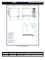
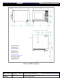
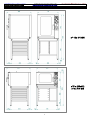
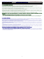
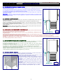
n°5 x 1/1 GN models
1.4B DIMENSIONI
1.4B DIMENSIONS
1.4B ABMESSUNGEN
1.4B DIMENSIONS
1.4B MEDIDAS
Modelli Modèle Dimensioni Dimensions Capacità e distanza (passo) tra le teglie Capacité et écart entre les grilles
Models Modelos Dimensions Medidas Capacity and distance between trays Capacidad y distancia (paso) entre las fuentes
Modelle Abmessungen Fassungsvermögen und Abstand der Bleche
05 x 1/1 GN
Electric cm 71 x 83 x h 58
n°05 x 1/1 GASTRO NORM
n°10 x 1/2 GASTRO NORM
67 mm
A
Connessione elettrica
Electrical connection
Elektroanschluss
Branchement électrique
Conexión eléctrica
B Entrata acqua φ 3/4″
Water inlet
φ
3/4”
Wasserzufuhr φ 3/4”
Arrivée eau
φ
3/4″
Entrada agua φ 3/4″
C Scarico cam. cottura φe 40mm
Water drainage
φ
40mm
Wasserablauf φ 40mm
Vidange eau
φ
40mm
Desagüe φ 40mm

ISTRUZIONI PER L’INSTALLATORE
INSTRUCTIONS FOR THE INSTALLER
ANLEITUNGEN FÜR DEN INSTALLATEUR
NOTICE POUR L'INSTALLATEUR
INSTRUCCIONES PARA EL INSTALADOR
SIMPLE Convection with humidification models 5 x 2/3 GN / 5-10 x 1/1 GN / 5 x (60x40)
5
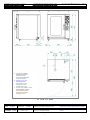
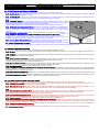
n°10 x 1/1 GN
1.3C DIMENSIONI
1.3C DIMENSIONS
1.3C ABMESSUNGEN
1.3C DIMENSIONS
1.3C MEDIDAS
Modelli Modèles Dimensioni Dimensions Capacità e distanza (passo) tra le teglie Capacité et écart entre les grilles
Models Modelos Dimensions Medidas Capacity and distance between trays Capacidad y distancia (paso) entre las fuentes
Modelle Abmessungen Fassungsvermögen und Abstand der Bleche
10 x 1/1GN
Electric cm 71 x 83 x h 91
n°10 x 1/1 GASTRO NORM
n°20 x 1/2 GASTRO NORM
67 mm
A
Connessione elettrica
Electrical connection
Elektroanschluss
Branchement électrique
Conexión eléctrica
B Entrata acqua φ 3/4″
Water inlet
φ
3/4”
Wasserzufuhr φ 3/4”
Arrivée eau
φ
3/4″
Entrada agua φ 3/4″
C Scarico cam. cottura φ 40mm
Water drainage
φ
40mm
Wasserablauf φ 40mm
Vidange eau
φ
40mm
Desagüe φ 40mm

ISTRUZIONI PER L’INSTALLATORE
INSTRUCTIONS FOR THE INSTALLER
ANLEITUNGEN FÜR DEN INSTALLATEUR
NOTICE POUR L'INSTALLATEUR
INSTRUCCIONES PARA EL INSTALADOR
SIMPLE Convection with humidification models 5 x 2/3 GN / 5-10 x 1/1 GN / 5 x (60x40)
6
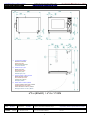
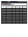
n°5 x (60x40) / n°4 x 1/1 GN
1.3C DIMENSIONI
1.3C DIMENSIONS
1.3C ABMESSUNGEN
1.3C DIMENSIONS
1.3C MEDIDAS
Modelli Modèles Dimensioni Dimensions Capacità e distanza (passo) tra le teglie Capacité et écart entre les grilles
Models Modelos Dimensions Medidas Capacity and distance between trays Capacidad y distancia (paso) entre las fuentes
Modelle Abmessungen Fassungsvermögen und Abstand der Bleche
5 x (60 x 40)
4 x 1/1GN
Electric cm 80 x 90 x h 58
n° 5 x (60 x 40)
n°4 x 1/1 GASTRO NORM
67 mm
A
Connessione elettrica
Electrical connection
Elektroanschluss
Branchement électrique
Conexión eléctrica.
B Entrata acqua φ 3/4″
Water inlet
φ
3/4”
Wasserzufuhr φ 3/4”
Arrivée eau
φ
3/4″
Entrada agua φ 3/4″
C Scarico camera cottura φ 50mm
Water drainage
φ
50mm
Wasserablauf φ 50mm
Vidange eau
φ
50mm
Desagüe φ 50mm
D Sfiato camera cottura φ 60mm
Cooking chamber relief valve
φ
60mm
Ablaßventil Garraum φ 60mm
Event chambre de cuisson
φ
60mm
Desagüe camara coccion
φ 60mm
La pagina si sta caricando...
La pagina si sta caricando...

ISTRUZIONI PER L’INSTALLATORE
INSTRUCTIONS FOR THE INSTALLER
ANLEITUNGEN FÜR DEN INSTALLATEUR
NOTICE POUR L'INSTALLATEUR
INSTRUCCIONES PARA EL INSTALADOR
SIMPLE Convection with humidification models 5 x 2/3 GN / 5-10 x 1/1 GN / 5 x (60x40)
9
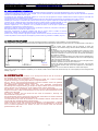
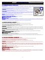
1.6 TABELLA DATI TECNICI Allacciamento elettrico
1.6 ECHNICAL DATA TABLE Electric connection
1.6 TABELLE TECHNISCHE DATEN Elektroanschluß
1.6 TABLEAU DES DONNEES TECHNIQUES Branchement électrique
1.6 TABLA DATOS TÉCNICOS Conexión eléctrica hornos
Modelli Potenza assorbita e voltaggio n° e potenza motori Potenza riscaldante Corrente assorbita Sez. cavo alimentazione
Models Power loading and voltage no. and motor power Heating power Absorbed current Feed cable section
Modelle Leistung und Spannung Anz.und Motorleistung Heizleistung Strom Querschnitt Anschlusskabel
Modèle Puissance absorbée et voltage n° et puissance moteur Puissance de chauffe Courant absorbé Section cable alimentation
Modelos Consumo de potencia y voltaje n° y potencia motores Potencia calefacción Consumo corriente Sección cable alimentacion
5 x 2/3 GN electric
5 kW 400 V+3N ∼ 50/60 Hz
1 x 200 W 4.8 kW 8.5 A n°5 x 1.5 mm
2
5 x 1/1GN electric
6 kW 400V+3N ∼ 50/60 Hz
1 x 200 W 5.8 kW 10 A n°5 x 2.5 mm
2
10 x 1/1GN electric
10 kW 400V+3N ∼ 50/60 Hz
2 x 200 W 9.6 kW 18 A n°5 x 4 mm
2
5 x (60 x 40) electric
6 kW 400V+3N ∼ 50/60 Hz
1 x 200 W 5.8 kW 10 A n°5 x 2.5 mm
2
Stanrdard
No standard

ISTRUZIONI PER L’INSTALLATORE
INSTRUCTIONS FOR THE INSTALLER
ANLEITUNGEN FÜR DEN INSTALLATEUR
NOTICE POUR L'INSTALLATEUR
INSTRUCCIONES PARA EL INSTALADOR
SIMPLE Convection with humidification models 5 x 2/3 GN / 5-10 x 1/1 GN / 5 x (60x40)
10
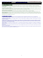
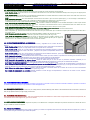
2.0 INSTALLAZIONE DELL’APPARECCHIO
Leggere attentamente questo libretto che fornisce importanti indicazioni riguardanti la sicurezza dell’installazione, l’uso e la manutenzione.
L’installazione dell’apparecchio deve essere eseguita, solo ed esclusivamente, da personale qualificato seguendo le istruzioni riportate nel presente
manuale e nel rispetto delle norme in vigore.
Gli impianti del gas, dell’acqua, dell’energia elettrica ed i locali nei quali gli apparecchi vengono installati devono essere eseguiti in conformità alle
corrispondenti norme di installazione e sicurezza.
I forni funzionanti a gas, devono sempre essere posizionati sotto una cappa di buon funzionamento che asporterà vapori e gas combusti.
(Il fabbisogno di aria per la combustione deve essere almeno di 2m
3
per ogni kW di potenza assorbita dagli apparecchi installati).
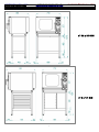
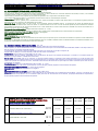
Collocare il forno in ambiente aerato e procedere alla messa a livello agendo sui piedini regolabili, in modo
tale che rimanga una distanza minima di 8cm tra il fondo del forno ed il piano di appoggio dei piedini.
Installare l’apparecchio in una posizione che ne permetta l’accesso al lato dx per le operazioni di
installazione, manutenzione e assistenza tecnica.
Mantenere le distanze minime tra le pareti del forno, (posteriore e laterale dx) e le pareti in muratura o le
altre apparecchiature come indicato in figura n°2.0A.
Rimuovere manualmente le pellicole protettive dalle parti in acciaio, prima di mettere in funzione
l’apparecchio, evitando l’uso di sostanze abrasive e/o di oggetti metallici.
Qualora il forno venga collocato sugli appositi supporti, da noi forniti su richiesta, fare attenzione che il foro
centrale dei piedini si innesti nel perno del supporto, questo incastro ne garantisce la stabilità, (Fig. 2.0).
2.0 INSTALLING THE APPLIANCE
Read this handbook through carefully as it provides important information to guarantee a safe installation, use and maintenance.
The appliance must be installed only and exclusively by qualified personnel following the instructions given herein and in compliance with current laws in
force.
The gas system, water, electricity and the premises on which the
appliances are installed comply with the relative installation and safety
standards.
Gas powered ovens must always be installed under an efficient suction
hood that takes steam and combusted gases away. (The quantity of air
needed for combustion is at least 2m
3
for each kW of power absorbed by
the appliances installed).
Install the oven on aerated premises and level with the adjustable feet,
keeping at least 8cm between the bottom of the oven and the supporting
surface on which the feet stand.
Install the appliance in a position that allows access to the right side for
installation, maintenance and technical assistance.
Maintain the minimum distances between the oven walls, (rear and right
side) and either the brick walls or the other appliances, as illustrated in
figure 2.0A.
Take the protective film off the stainless steel parts by hand before starting the appliance. Do not use abrasive substances and/or metal objects.
If the oven is placed on its supports, supplied by us on request, make sure the centre hole of the feet snap on to the support pin which will guarantee
stability, (Fig. 2.0).
2.0 GERÄTEINSTALLATION
Dieses Handbuch aufmerksam durchlesen, da es wichtige Informationen über die Sicherheit bei
der Aufstellung, die Bedienung und Wartung enthält.
Die Geräteinstallation darf ausschließlich von Fachpersonal, gemäß den in diesem Handbuch
angeführten Anleitungen und den gültigen Normen durchgeführt werden.
Die Gas-, Wasser- und Stromversorgungsanlagen, sowie der Aufstellort, müssen den geltenden
Installations- und Sicherheitsbestimmungen entsprechen.
Die gasbetriebenen Backöfen müssen immer unter einer einwandfrei funktionierenden
Dunstabzugshaube aufgestellt werden, die Dämpfe und Abgase ableitet. (Die für die Verbrennung
nötige Luftzufuhr muss mindestens 2m
3
pro kW aufgenommener Leistung entsprechen.
Den Backofen in einem gut belüfteten Raum aufstellen und mit den höhenverstellbaren Füßen
waagrecht ausrichten, sodass ein Mindestabstand von 8cm zwischen dem Backofenboden und der
Stellfläche der Füße bleibt.
Das Gerät so aufstellen, dass die rechte Seite des Geräts für Installations-, Wartungs- und
Reparaturarbeiten zugänglich sind.
Den Mindestabstand zwischen den Wänden des Backofens (hintere Wand und rechte Seitenwand)
und Mauern oder anderen Geräten beachten (Abb.2.0A).
Vor Inbetriebnahme des Geräts die Schutzfolie von den Stahlteilen abziehen. Dafür dürfen keine
Scheuermittel bzw. Metallgegenstände verwendet werden.
Sollte der Backofen auf den dafür vorgesehenen Abstellflächen - auf Anfrage lieferbar - aufgestellt
werden, ist darauf zu achten, dass der entsprechende Stellzapfen der Abstellfläche in das zentrale
Loch im Stellfuß eingeschoben wird, wodurch ein fester und sicherer Stand des Backofens
gewährleistet wird, (Abb. 2.0).
Fig. 2.0
Abb. 2.0
Fig.2.0A
A
bb.2.0A
La pagina si sta caricando...

ISTRUZIONI PER L’INSTALLATORE
INSTRUCTIONS FOR THE INSTALLER
ANLEITUNGEN FÜR DEN INSTALLATEUR
NOTICE POUR L'INSTALLATEUR
INSTRUCCIONES PARA EL INSTALADOR
SIMPLE Convection with humidification models 5 x 2/3 GN / 5-10 x 1/1 GN / 5 x (60x40)
12
2.2 COLLEGAMENTO ELETTRICO
L’apparecchio consegnato è predisposto per il funzionamento alla tensione riportata sulla targhetta “caratteristiche” applicata sul fianco dx
dell’apparecchio.
La morsettiera di allacciamento è accessibile dal lato dx dell’apparecchio, smontando il fianco di rivestimento.
Prima di procedere all’applicazione del cavo, smontare la protezione in acciaio fissata al basamento del forno con le relative viti, (vedi fig.2.2A)
introdurre il cavo nel raccordo di bloccaggio e introdurlo nel vano della morsettiera dal foro con guarnizione del basamento in prossimità della stessa.
A collegamento elettrico eseguito rimontare la protezione in acciaio precedentemente rimossa.
Il cavo flessibile, per il collegamento elettrico, deve avere caratteristiche non inferiori a quello con isolamento in gomma H07 RN-F con la sezione dei
conduttori riportata nei dati tecnici.
Installare, a monte dell’apparecchio, un interruttore automatico di protezione e di portata adeguata, che abbia un’apertura dei contatti superiore a 3 mm.
E’ indispensabile collegare l’apparecchiatura ad un efficiente impianto di terra; a tale scopo sulla morsettiera di allacciamento c’è il morsetto, con il
relativo simbolo
, al quale deve essere connesso il conduttore di terra.
L’apparecchiatura deve trovare inserimento in un sistema equipotenziale, (Fig. 2.2) la cui efficacia deve
essere in conformità alla normativa in vigore. Il collegamento deve essere eseguito tramite la vite collocata in
prossimità del pressacavo di alimentazione, contrassegnata dalla sigla EQUIPOTENTIAL.
Il Costruttore declina ogni responsabilità qualora questa importante norma antinfortunistica non
venga rispettata.
2.2A VERIFICA SENSO ROTAZIONE MOTORI (solo per motori trifasi)
Verificare che il senso di rotazione dei ventilatori corrisponda alla direzione della freccia riportata nel
pannello in acciaio inossidabile di convogliamento aria, posto all’interno della camera di cottura, qualora la
rotazione risulti contraria, invertire tra loro due fasi sulla morsettiera di alimentazione.
2.2 ELECTRICAL CONNECTION
When the appliance is delivered it is set to work at the voltage given on the rating plate affixed on the right
side of the appliance.
The terminal board used for connecting can be accessed from the right of the appliance, removing the side
panel.
Before connecting the cable, remove the steel protection fixed to the ovens base with its specific screws, (see
Fig. 2.2A)insert the cable in the clamp-connector and then in the terminal board zone, passing through the
hole with the gasket near the terminal board. Once the electric connection has been carried out, reassemble the steel protection previously removed.
The specifications of the flexible cable for the electrical connection should be no lower than those of the type with rubber insulation H07 RN-F, with the
cross section of the wires as given in the technical data.
Install a circuit breaker of a suitable capacity upstream from the appliance, making sure it
has an opening between the contacts of at least 3-mm.
It is essential to connect the appliance to an effective earthing system; (Fig. 2.2) for this
purpose the relative terminal with the symbol
to which the earth wire is to be connected
is on the terminal board.
The effectiveness of the equipotential system of which the appliance is part of, must
conform to current standards. Connect using the screw you find near the power cable’s relief
cable strain, marked with the word EQUIPOTENTIAL.
The Manufacturer declines all and every responsibility if this important accident
prevention norm is not complied with
2.2A CHECKING MOTOR ROTATION DIRECTION (only for three-phase motors).
Check that the fans’ rotation direction is the same as that of the arrow on the stainless
steel air-conveying panel, located inside the oven. If they are rotating in the opposite
direction, reverse two phases on the supply terminal board.
2.2 ELEKTROANSCHLUSS
Das Gerät wird werksgemäß für den Betrieb mit der auf dem Typenschild (auf der rechten
Seite des Geräts angebracht) angegebenen Versorgungsspannung eingestellt.
Die Anschlussklemmleiste wird durch Abnehmen der rechten Seitenwand zugänglich.
Bevor dem Netzkabel zu verbinden, das Schutz-Stahlblech, das zur Grundfläche des Ofens
mit den spezifischen Schrauben befestigt ist, abnehmen (Abb. 2.2A). Das Kabel in den
Kabelklemmen stecken und durch das Loch (im Raum der Klemmleiste) mit der Dichtung in der Nähe vom Klemmleiste einführen.
Als die elektrische Verbindung durchgeführt wurde, nochmals das Schutz-Stahlblech wieder anschrauben.
Der Anschluss muss mit einem Netzkabel mit den Eigenschaften des Typs H07 RN-F mit Gummiisolierung durchgeführt werden. Die Leiterquerschnitte
müssen jenen unter „Technische Daten” angeführten entsprechen.
Vor dem Gerät muss ein automatischer Schutzschalter, mit mindestens 3 mm Kontaktöffnungsweite, eingebaut werden.
Das Gerät muss unbedingt geerdet werden. Zu diesem Zweck befindet sich auf der Anschlussklemmleiste eine Klemme mit entsprechendem Symbol
, an die der Erdleiter angeschlossen werden muss.
Des weiteren muss das Gerät in ein Potentialausgleichssystem (Abb. 2.2) eingeschlossen werden, dessen Wirksamkeit den geltenden Richtlinien
entsprechen muss. Der Anschluss wird mit der Schraube durchgeführt, die mit EQUIPOTENTIAL gekennzeichnet ist und sich in der Nähe der
Kabelklemme befindet.
Die Herstellerfirma übernimmt bei Nichtbeachtung dieser Unfallverhütungsmaßnahme keine Verantwortung.
2.2A ÜBERPRÜFUNG ROTATIONSRICHTUNG DER MOTOREN (nur für Dreiphasenmotoren)
Sicherstellen, dass die Rotationsrichtung der Ventilatoren der Pfeilrichtung (an der Edelstahlplatte der Luftsammelleitung innerhalb des Garraums)
entspricht. Andernfalls, die beiden Phasen an der Versorgungsklemmleiste umkehren.
Fig. 2.2
Abb. 2.2
Fig. 2.2A
Abb. .2.2A
La pagina si sta caricando...

ISTRUZIONI PER L’INSTALLATORE
INSTRUCTIONS FOR THE INSTALLER
ANLEITUNGEN FÜR DEN INSTALLATEUR
NOTICE POUR L'INSTALLATEUR
INSTRUCCIONES PARA EL INSTALADOR
SIMPLE Convection with humidification models 5 x 2/3 GN / 5-10 x 1/1 GN / 5 x (60x40)
14
2.3 COLLEGAMENTO IDRAULICO - ENTRATA ACQUA (Fig. 2.3)
I forni sono provvisti di un raccordo di entrata-acqua situato nel retro dell’apparecchiatura. Porre sempre tra l’apparecchio e la rete di alimentazione
dell’acqua una valvola di intercettazione con comando facilmente azionabile, si consiglia inoltre il montaggio di un filtro a cartuccia sulla tubazione di
entrata dell’acqua.
L’elettrovalvola (A) alimenta tramite l’iniettore (B) il sistema di generazione del vapore nella camera di cottura.
L’acqua di alimentazione deve essere idonea al consumo umano e avere le seguenti caratteristiche:
Temperatura: compresa tra 15 – 20°C
Qualora il forno venga fornito senza il sistema, (OPTIONAL) per la condensazione dei vapori nel tubo di scarico
l’allacciamento idrico può essere effettuato con acqua calda alla temperatura massima di 90°C,
Durezza totale: compresa tra 4 e 8°Francesi.
Si consiglia di installare sempre un decalcificatore a monte dell’apparecchio, atto a mantenere il valore della
durezza dell’acqua entro detti valori, Il funzionamento del forno con acqua di durezza superiore porta alla formazioni
di incrostazioni calcaree sulle pareti della camera di cottura, eventuali interventi di assistenza tecnica necessari alla
riparazione di danni causati dal calcare, non saranno considerati “in garanzia”.
Pressione: compresa tra 100 e 200 KPa (1 – 2 bar).
N.B. valori di pressione più elevati comportano solo un dispendio del consumo di acqua e possono compromettere il
corretto funzionamento di alcuni componenti.
Concentrazione massima di ione cloruro (Cl-): inferiore a 150 mgr/litro.
Concentrazione di Cloro (Cl
2
): inferiore a 0.2 mg/litro.
Ph: maggiore di 7.
Conducibilità elettrica: compresa tra 50 e 2000 μS/cm.
Attenzione: L’utilizzo di sistemi di trattamento dell’acqua che determinano valori diversi da quelli sopra indicati non è ammesso pena il totale
decadimento della garanzia. Eventuali impianti dosatori di sostanze atte a evitare la formazione di incrostazioni nelle tubazioni (per esempio: dosatori di
polifosfati) sono altresì vietati perché possono compromettere il corretto funzionamento dell’apparecchiatura.
2.3 HYDRAULIC CONNECTION – WATER INLET
(Fig. 2.3)
The ovens have a water inlet coupling at the back.
Always install an on-off valve between the appliance and the water mains, making sure it is easy to operate.
We also suggest installing a cartridge filter on the water inlet pipe.
The solenoid valve (A) supplies the steam generation system into the cooking chamber by means of the injector (B)
The water must be suitable to human use with the following characteristics:
Temperature:
included between 15 – 20 °C
In case the oven is supplied without steam condensation system (OPTIONAL) inside the drain pipe, the plumbing connection must be done with hot
water at a max. temperature of 90° C.
Total hardness:
included between 4 and 8 °French degree, it is advisable to install a softener upstream from the appliance that will maintain the
hardness level at the mentioned values. The oven’s running with water that has a higher hardness level will not be long before scale forms on the walls
of the oven and in this case the technical assistance required to repair such damage is not covered by the guarantee.
Pressure:
included between 100 and 200 KPa (1 – 2 bar).
Attention higher water pressure values result in increased water consumption and can compromise the correct functioning of some components.
Maximum chloride concentration (Cl-):
less than 150 mgr/litre.
Chlorine concentration (Cl
2
):
less than 0.2 mg/litre.
Ph:
more than 7.
Water conductivity:
included between 50 and 2000
μ
S/cm.
Attention:
Water treatment systems that bring to different values to the ones above mentioned automatically invalidate the guarantee.
The use of dosing systems designed to prevent the build-up of lime-scale in pipes (i.e. polyphosphate dosing systems) is also prohibited since it may
impair the performance of the appliance.
2.3 ANSCHLUSS ANS WASSERNETZ – WASSERZUFUHR (Abb. 2.3)
Die Geräte sind auf der Rückseite mit einem Wasseranschluss ausgerüstet.
Zwischen dem Gerät und dem Wasserversorgungsnetz muss ein leicht zugängliches Absperrventil zwischengeschaltet werden.
Außerdem empfiehlt es sich, in der Wasserzuleitung einen Filter mit Einsatz zu montieren.
Das Elektroventil (A) versorgt die Dampferzeugung in den Garraum durch die Einspritzdüse (B)
Die Wasserversorgung muss für den Menschengebrauch geeignet sein und soll die folgenden Eigenschaften haben:
Temperatur: muß zwischen 15 und 20°C liegen
Falls der Ofen ohne Wrasenniederschlagsystem (OPTIONAL) am Wasserablauf geliefert wird, kann der Wasseranschluss mit warmem Wasser mit max.
Temperatur von 90° C gemacht werden.
Wasserhärte: Diesem Gerät muß Wasser zugeführt werden, dass eine Härte von 4 bis 8 französischen Graden aufweist. Es wird empfohlen einen
Entkalker dem Gerät beizugeben, damit der Härtegrad des Wassers zwischen diesen Werten liegt. Wird Wasser mit höherem Härtegrad verwendet,
entstehen innerhalb kurzer Zeit Kalkablagerungen auf den Garraumwänden. Eventuelle, dadurch notwendige Reparaturen werden nicht von der
Garantie gedeckt.
Wasserdruck: zwischen 100 und 200 KPa (1 – 2 bar).
ACHTUNG. Höhere Drücke führen zu übermäßigen Wasserverbrauch und können wichtige Komponente beschädigen.
Maximale Chloridkonzentration (Cl-): unter 150 mgr/Liter.
Chlorkonzentration (Cl
2
): unter 0.2 mg/Liter.
Ph: über 7
Leitfähigkeit des Wassers: von 50 bis 2000 μS/cm.
Achtung: Die Verwendung anderer Wasseraufbereitungssysteme als das von der Herstellerfirma gelieferte ist unzulässig und führt zum vollständigen
Verfall der Garantie. Der Einsatz von Geräten zur Dosierung von Mitteln zur Vermeidung von Ablagerungen in den Rohrleitungen (z.B. Polyphosphat-
Dosierer) ist ebenfalls untersagt, da diese die einwandfreie Funktion der Maschine beeinträchigen können.
Fig. 2.3
Abb. 2.3
La pagina si sta caricando...

ISTRUZIONI PER L’INSTALLATORE
INSTRUCTIONS FOR THE INSTALLER
ANLEITUNGEN FÜR DEN INSTALLATEUR
NOTICE POUR L'INSTALLATEUR
INSTRUCCIONES PARA EL INSTALADOR
SIMPLE Convection with humidification models 5 x 2/3 GN / 5-10 x 1/1 GN / 5 x (60x40)
16
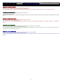
2.4 COLLEGAMENTO IDRAULICO - SCARICO ACQUA
I forni sono dotati di uno scarico acqua situato sul retro dell’apparecchio; il collegamento idraulico deve essere effettuato direttamente sull’estremità del
tubo di scarico in acciaio inox.
Lo scarico deve essere privo di sifone e realizzato con tubi rigidi e resistenti alla temperatura di 110°C.
E’ assolutamente necessario che il diametro del tubo di scarico non venga ridotto e che la sua tubazione
sia a pressione atmosferica, con l’opportuna presa d’aria a imbuto.
L’eventuale intasamento del tubo di scarico può provocare uscita di vapore dalla porta e cattivi odori
nella camera di cottura.
Attenzione: L’impianto di scarico deve essere installato in modo tale da evitare che eventuali vapori
emessi dalla presa d’aria a imbuto “air break” raggiungano le aperture di aereazione presenti sul fondo
del forno. (Fig. 2.4 e 2.4A)
2.4 PLUMBING – WATER DRAINAGE
Drainage for the water is at the back of the oven and must be connected directly to the end of the
stainless steel drainpipe.
The drain must have no trap and be made in rigid pipes that can withstand a temperature of 110°C.
Under no circumstances must pipe diameter be reduced. The actual pipe should be at atmospheric
pressure with the appropriate funnel type air intake.
If the drainpipe is clogged for any reason steam can escape from the door and bad smells can be created
inside in the oven.
Important:
The drain system must be installed so that any vapours coming from the open drain do not
enter the aeration vents under the appliance. (Fig. 2.4 and 2.4A).
2.4 ANSCHLUSS AN DAS WASSERNETZ – WASSERABLAUF
Die Backöfen sind auf der Rückseite mit einem Wasserablauf ausgerüstet; sodass der Wasseranschluss
direkt am Edelstahl-Ablaufrohr vorgenommen werden muss.
Der Ablauf darf keinen Siphon haben und muss aus bis zu 110°C hitzebeständig, unbiegsamen Rohren
hergestellt werden.
Der Durchmesser des Ablaufrohrs darf auf keinen Fall verringert werden und die Rohrleitung muss für den atmosphärischen Druck geeignet und mit der
notwendigen trichterförmigen Luftansaugung ausgestattet sein.
Eine eventuelle Verstopfung des Ablaufrohrs kann einen Dampfaustritt aus der Tür und eine Geruchbildung im Garraum zur Folge haben.
Achtung: Die Abluftanlage muß so installiert werden, dass eventuell vom „Air-Break“ austretende Dämpfe nicht in die Belüftungsöffnungen am Boden
des Gerätes gelangen können. (Abb. 2.4 und 2.4A)
2.4 RACCORDEMENT HYDRAULIQUE – VIDANGE D'EAU
Les fours sont équipés d’un tuyau de vidange de l’eau placé à l’arrière de l'appareil; le raccordement
hydraulique doit être effectué directement sur l'extrémité du tuyau de vidange en acier inox.
Le système de vidange ne doit pas avoir de siphon et doit être réalisé avec des tuyaux rigides et
résistants à une température de 110°C.
Le diamètre du tuyau de vidange ne peut pas être réduit et il est absolument nécessaire que le
raccordement au conduit soit à pression atmosphérique, avec une adéquate prise d’air à entonnoir.
L’obstruction du tuyau de vidange peut provoquer une sortie de vapeur par la porte du four et des
mauvaises odeurs à l’intérieur de l’enceinte de cuisson.
Attention: installer le système d’évacuation de façon à éviter l’émission de vapeurs par l’Air-break dans les
conduits d’aération installés dans le fond de l’appareil. (Fig. 2.4 et 2.4A)
2.4 CONEXIÓN HÍDRICA – DESAGÜE
Los hornos disponen de un desagüe situado en la parte trasera del aparato; la conexión hídrica debe ser
efectuada directamente en el extremo del tubo de desagüe en acero inoxidable.
El desagüe no debe tener sifón y debe realizarse con tubos
rígidos y resistentes a temperaturas de 110°C.
Es terminantemente necesario que el diámetro del tubo de
desagüe no se reduzca y que su tubería quede a la presión
atmosférica, con la oportuna toma de aire con forma de
embudo.
El eventual atasco del tubo de desagüe puede causar la salida
de vapor por la puerta del horno y malos olores en la cámara
de cocción.
Atención: instalar el sistema de evacuación de modo che los
vapores emitidos por el Air-Break alcancen la abertura de
aireación colocada al fondo del aparato. (Fig. 2.4 y 2.4A)
2
°
m
i
n
.
> 1 cm
< 30 cm
2
°
m
i
n
.
1>cm
> 50 cm
Fig. 2.4
Abb. 2.4
Fig. 2.4A
Abb. 2.4A

ISTRUZIONI PER L’INSTALLATORE
INSTRUCTIONS FOR THE INSTALLER
ANLEITUNGEN FÜR DEN INSTALLATEUR
NOTICE POUR L'INSTALLATEUR
INSTRUCCIONES PARA EL INSTALADOR
SIMPLE Convection with humidification models 5 x 2/3 GN / 5-10 x 1/1 GN / 5 x (60x40)
17
3.0 AUTOMATISMI DI CONTROLLO E SICUREZZA
I forni sono dotati di una serie di automatismi di controllo e sicurezza dei circuiti elettrici ed idraulici
3.0A Fusibile da 2A: è inserito nel circuito ausiliario per la protezione da corto circuito dell’impianto elettrico ed è alloggiato nell’apposito supporto
collocato sulla staffa di fissaggio dei contattori.
3.0B Fusibile da 1A: è inserito nel circuito elettrico di alimentazione del controllore elettronico, (versioni “Electronic”) per la protezione da corto
circuito ed è alloggiato nell’apposito supporto collocato sulla staffa di fissaggio dei contattori.
3.0C
3.0D Protezione motore: una sonda termica disinserisce il motore qualora per motivi diversi si possa
manifestare un sovraccarico, l’intervento della protezione determina l’arresto del motore e il conseguente
disinserimento delle resistenze o del bruciatore di gas del riscaldamento.
Il ripristino della sonda avverrà automaticamente con la diminuzione della temperatura del motore.
3.0E Termostato sicurezza camera forno: disinserisce le resistenze riscaldanti nei modelli elettrici o
chiude la valvola del gas nei relativi apparecchi, in caso di anomalie derivate da surriscaldamento, il
ripristino dovrà essere eseguito manualmente dopo la verifica delle cause che ne hanno causato
l’intervento.
3.0F Interruttore apertura porta: arresta il funzionamento del forno quando viene aperta la porta.
3.0G Sistema termostatico per la condensazione dei vapori di scarico (Optional): è composto di
un elettrovalvola, comandata da un termostato il cui sensore è alloggiato a contatto con lo scarico.
L’elettrovalvola tramite l’inettore (G) provvede ad immettere acqua fredda nel tubo di scarico per
condensare il vapore quando viene raggiunta la temperatura di 90°C, (Fig. 3.0G).
3.0H Valvola sfiato camera (Optional): ha la funzione di regolare l’umidità all’interno della camera di
cottura e viene attivata manualmente tramite il pommello (A), situato sopra la porta. (Fig. 3.0H).
3.0I Sonda di temperatura al cuore: (fornita su richiesta nei modelli “Analogic” e di serie nei modelli
“Electronic”) permette, tramite l’apposito spillone da infilzare nel cibo da cuocere, l’esatto controllo della temperatura al cuore.
3.0 CONTROL AND SAFETY DEVICES
The ovens are equipped with a set of control and safety devices for the electric and hydraulic circuits.
3.0A 2A fuse:
it is in the auxiliary circuit to protect against short circuiting of the electrical system and is inside its own support on the contactors’s
fixing bracket.
3.0B 1A fuse:
it is in the electronic controller’s electrical supply circuit, (“Electronic” versions) to protect against short circuiting and is housed inside
its own support on the contactors’ fixing bracket.
3.0C
3.0D Motor overload protection:
a thermal probe disengages the motor when, for various reasons, there is an overload. When the overload
protection triggers it stops the motor and also disconnects the heating elements or the gas valve.
The probe is reset automatically when motor temperature drops.
3.0E Oven safety thermostat:
disconnects the heating element or the gas valve when anomalies related to overheating occur. Subsequent re-set
will have to be done manually when causes for thermostat operation have been determined.
3.0F Door microswitch:
it stops the oven working when the door is opened.
3.0G Thermostat system for condensation of discharge steam (Optional):
it comprises a solenoid valve controlled by a thermostat whose
sensor is housed in contact with the discharge. The solenoid valve, via the injector (G), lets cold water into the drainpipe to condense the steam when
a temperature of 90°C is reached, (Fig. 3.0G).
3.0H Oven relief valve (Optional):
(Optional) its job is to adjust humidity inside the cooking chamber . The valve is manually activated acting on the
knob (A) (Fig.3.0H)on top of the door.
3.0I Heart temperature probe:
(supplied on request with the “Analogic” models and a standard feature with the “Electronic” models) with a special
sensor inserted in the food to cook you can control the exact temperature right in the centre.
3.0 KONTROLL- UND SICHERHEITSAUTOMATISMEN
Die Backöfen sind mit einer Reihe von automatischen Kontroll- und Sicherheitsvorrichtungen für Strom- und Wasserkreise ausgerüstet
3.0A Schmelzsicherung 2A: ist in den Hilfsstromkreis eingebaut, um die elektrische Anlage vor einem Kurzschluss zu sichern und befindet sich im
dafür vorgesehenen Träger am Befestigungsbügel der Kontaktgeber.
3.0B Schmelzsicherung 1A: ist in den elektrischen Versorgungsstromkreis der elektronischen Kontrolle eingebaut (Electronic Modelle), um vor
einem Kurzschluss zu sichern und befindet sich im dafür vorgesehenen Träger am Befestigungsbügel der Kontaktgeber.
3.0C
3.0D Überhitzungsschutzschalter Motor: bei Überbelastung schaltet eine Hitzesonde den Motor aus, indem sie die Heizkörper ausschaltet oder
die Gassicherheitsventile zudreht. Der Motor wird somit vor einer durch Funktionsstörungen hervorgerufenen Überhitzung geschützt.
Die Rückstellung des Schalters erfolgt nach Abkühlen des Motors automatisch.
3.0E Sicherheitsthermostat Garraum: hat die Funktion, bei erhöhten Temperaturen im Garraum die Gaszufuhr zu unterbrechen. Die Rückstellung
des Thermostats muss manuell erfolgen, nachdem die Ursachen, die zur Überhitzung geführt haben, behoben worden sind.
3.0F Türmikroschalter: unterbricht den Backofenbetrieb, jedes Mal, wenn die Tür geöffnet wird.
3.0G Thermostatsystem für die Kondensation der Abflussdämpfe (Optional): besteht aus einem Magnetventil, das von einem Thermostat mit
Sensor am Abfluss gesteuert wird. Das Magnetventil führt über die Düse (G) dem Abflussrohr Kaltwasser zu, um den Dampf bei Erreichen von einer
Temperatur von 90°C zu kondensieren. (Abb.3.0G)
3.0H Entlüftungsventil Garraum (Optional): hat die Aufgabe, die Feuchtigkeit im Garraum zu regeln. Das Ventil, das auf der Tür aufgestellt ist,
wird mit dem Knauf (A) handaktiviert (Abb. 3.0H).
3.0I Kerntemperaturfühler: ermöglicht durch das Speisenthermometer, das in die Speisen gesteckt wird, eine genaue Temperaturkontrolle.
Fig. 3.0G
Abb. 3.0G
La pagina si sta caricando...

ISTRUZIONI PER L’INSTALLATORE
INSTRUCTIONS FOR THE INSTALLER
ANLEITUNGEN FÜR DEN INSTALLATEUR
NOTICE POUR L'INSTALLATEUR
INSTRUCCIONES PARA EL INSTALADOR
SIMPLE Convection with humidification models 5 x 2/3 GN / 5-10 x 1/1 GN / 5 x (60x40)
19
CONTROLLO DELLE FUNZIONI
Mettere in funzione l’apparecchio come da ISTRUZIONI PER L’UTENTE.
Eseguire una prova di tenuta delle condutture idriche e quelle del gas.
E’ indispensabile spiegare all’utente il funzionamento dell’apparecchiatura e consegnargli il libretto istruzioni a cui si dovrà attenere nell’uso.
CHECKING THE FUNCTIONS
Start the appliance following the INSTRUCTIONS FOR THE USER.
Test the water pipes for leaks.
It is essential to explain to the user exactly how the appliance works and to supply him with the instruction handbook that he must follow when using the
oven.
KONTROLLE DER FUNKTIONEN
Das Gerät laut ANWEISUNGEN FÜR DEN BENUTZER in Betrieb nehmen.
Die Wasserleitungen auf ihre Dichtheit prüfen.
Der Benutzer muss in den Gerätebetrieb eingewiesen werden und es muss ihm die Bedienungsanleitung, die sorgfältig zu befolgen ist, ausgehändigt
werden.
CONTRÔLE DES FONCTIONS
Mettre en marche l'appareil en suivant les instructions de LA NOTICE RÉSERVÉE À L’UTILISATEUR.
Faire un test d'étanchéité des conduites hydrauliques et du gaz.
Il est indispensable de bien expliquer le fonctionnement de l'appareil à l'utilisateur et qu’il garde à portée de main la notice d'emploi qu'il devra suivre
attentivement lors de l'utilisation de l'appareil.
CONTROL DE LAS FUNCIONES
Poner en marcha el aparato como indicado en las INSTRUCCIONES PARA EL USUARIO.
Efectuar una prueba de estanqueidad de las tuberías del agua.
Es indispensable explicar al usuario el funcionamiento del aparato y entregarle el folleto de instrucciones que deberá consultar durante el uso del
aparato.
-
 1
1
-
 2
2
-
 3
3
-
 4
4
-
 5
5
-
 6
6
-
 7
7
-
 8
8
-
 9
9
-
 10
10
-
 11
11
-
 12
12
-
 13
13
-
 14
14
-
 15
15
-
 16
16
-
 17
17
-
 18
18
-
 19
19
-
 20
20


Whirlpool ADN 555 Guida utente
- Tipo
- Guida utente
- Questo manuale è adatto anche per
in altre lingue
- English: Whirlpool ADN 555 User guide
- français: Whirlpool ADN 555 Mode d'emploi
- español: Whirlpool ADN 555 Guía del usuario
- Deutsch: Whirlpool ADN 555 Benutzerhandbuch
Documenti correlati
-
Whirlpool ADN 553 Manuale utente
-
Whirlpool ADN 500 Guida d'installazione
-
-
-
-
-
Whirlpool AGB 631/WP Guida d'installazione
-
-