Dometic DSP612, DSP624, DSP1012, DSP1024, DSP1512, DSP1524, DSP2012, DSP2024 Istruzioni per l'uso
- Tipo
- Istruzioni per l'uso

DSP612, DSP624, DSP1012, DSP1024,
DSP1512, DSP1524, DSP2012, DSP2024
Sine wave inverter
Installation and Operating Manual. . . . . . . . 3
Sinus-Wechselrichter
Montage- und Bedienungsanleitung . . . . . 21
Onduleur sinusoïdal
Instructions de montage
et de service . . . . . . . . . . . . . . . . . . . . . . . . .40
Convertidor de ondas seno
Instrucciones de montaje y de uso . . . . . . .60
Conversor sinusoidal
Instruções de montagem e manual de
instruções . . . . . . . . . . . . . . . . . . . . . . . . . . .80
Inverter sinusoidale
Istruzioni di montaggio e d’uso . . . . . . . . 100
Sinus ondulator
Montagehandleiding en
gebruiksaanwijzing . . . . . . . . . . . . . . . . . .120
Sinus ensretter
Monterings- og betjeningsvejledning. . . 139
Sinus växelriktare
Monterings- och bruksanvisning . . . . . . . 157
Sinus vekselretter
Monterings- og bruksanvisning. . . . . . . . 175
Sinus -vaihtosuuntaaja
Asennus- ja käyttöohje . . . . . . . . . . . . . . . 193
Синусоидальный инвертор
Инструкция по монтажу и эксплуатации 211
Przetwornica sinusoidalna
Instrukcja montażu i obsługi. . . . . . . . . . . 232
Sínusový menič napätia
Návod na montáž a uvedenie
do prevádzky. . . . . . . . . . . . . . . . . . . . . . . 252
Sinusový měnič
Návod k montáži a obsluze . . . . . . . . . . . 270
Szinuszos inverter
Szerelési és használati útmutató . . . . . . . 288
EN
DE
FR
ES
PT
IT
NL
DA
SV
NO
FI
RU
PL
SK
CS
HU
ENERGY & LIGHTING
SINEPOWER
DSP600-2000--IO-16s.book Seite 1 Montag, 7. Mai 2018 1:39 13

DSP600-2000--IO-16s.book Seite 2 Montag, 7. Mai 2018 1:39 13

EN
SinePower
3
Please read this instruction manual carefully before installation and first
use, and store it in a safe place. If you pass on the product to another
person, hand over this instruction manual along with it.
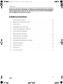
Table of contents
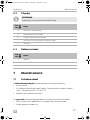
1 Explanation of symbols. . . . . . . . . . . . . . . . . . . . . . . . . . . . . . . . . . . . . . . . . . .4
2 General safety instructions . . . . . . . . . . . . . . . . . . . . . . . . . . . . . . . . . . . . . . . .4
3 Scope of delivery . . . . . . . . . . . . . . . . . . . . . . . . . . . . . . . . . . . . . . . . . . . . . . .7
4 Target group for this manual. . . . . . . . . . . . . . . . . . . . . . . . . . . . . . . . . . . . . . .8
5 Intended use . . . . . . . . . . . . . . . . . . . . . . . . . . . . . . . . . . . . . . . . . . . . . . . . . . .8
6 Technical description . . . . . . . . . . . . . . . . . . . . . . . . . . . . . . . . . . . . . . . . . . . .8
7 Fitting the inverter . . . . . . . . . . . . . . . . . . . . . . . . . . . . . . . . . . . . . . . . . . . . . .10
8 Connecting the inverter . . . . . . . . . . . . . . . . . . . . . . . . . . . . . . . . . . . . . . . . .12
9 Using the inverter . . . . . . . . . . . . . . . . . . . . . . . . . . . . . . . . . . . . . . . . . . . . . .14
10 Cleaning and caring for the inverter. . . . . . . . . . . . . . . . . . . . . . . . . . . . . . . .16
11 Troubleshooting . . . . . . . . . . . . . . . . . . . . . . . . . . . . . . . . . . . . . . . . . . . . . . .17
12 Warranty . . . . . . . . . . . . . . . . . . . . . . . . . . . . . . . . . . . . . . . . . . . . . . . . . . . . .18
13 Disposal . . . . . . . . . . . . . . . . . . . . . . . . . . . . . . . . . . . . . . . . . . . . . . . . . . . . . .18
14 Technical data . . . . . . . . . . . . . . . . . . . . . . . . . . . . . . . . . . . . . . . . . . . . . . . . .18
DSP600-2000--IO-16s.book Seite 3 Montag, 7. Mai 2018 1:39 13

EN
Explanation of symbols SinePower
4
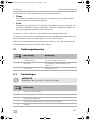
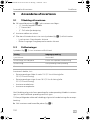
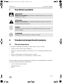
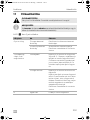
1 Explanation of symbols
D
!
A
I
2 General safety instructions
2.1 General safety
The manufacturer accepts no liability for damage in the following cases:
• Faulty assembly or connection
• Damage to the product resulting from mechanical influences and incorrect
connection voltage
• Alterations to the product without express permission from the manufacturer
• Use for purposes other than those described in the operating manual
Note the following basic safety information when using electrical devices to protect
against:
• Electric shock
•Fire hazards
•Injury
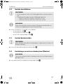
DANGER!
Safety instruction: Failure to observe this instruction will cause fatal or
serious injury.
WARNING!
Safety instruction: Failure to observe this instruction can cause fatal or
serious injury.
NOTICE!
Failure to observe this instruction can cause material damage and impair
the function of the product.
NOTE
Supplementary information for operating the product.
DSP600-2000--IO-16s.book Seite 4 Montag, 7. Mai 2018 1:39 13

EN
SinePower General safety instructions
5
2.2 General safety
D
DANGER!
• In the event of fire, use a fire extinguisher which is suitable for electrical
devices.
!
WARNING!
• Only use the device as intended.
• Ensure that the red and black terminals never come into contact.
• Disconnect the device from the power supply:
– Before cleaning and maintenance
– Before changing a fuse
• If you disassemble the device:
– Detach all connections
– Make sure that no voltage is present at any of the inputs and out-
puts
• The device may not be used if the device itself or the connection cable
are visibly damaged.
• If this power cable for this device is damaged, it must be replaced by
the manufacturer, customer service or a similarly qualified person in
order to prevent safety hazards.
• This device may only be repaired by qualified personnel. Inadequate
repairs may cause serious hazards.
• This device can be used by children aged 8 years or over, as well as by
persons with diminished physical, sensory or mental capacities or a
lack of experience and/or knowledge, providing they are supervised
or have been taught how to use the device safely and are aware of the
resulting risks.
• Electrical devices are not toys.
Always keep and use the appliance out of the reach of children.
• Children must be supervised to ensure that they do not play with the
device.
A
NOTICE!
• Before start-up, check that the voltage specification on the type plate
is the same as that of the power supply.
• Ensure that other objects cannot cause a short circuit at the contacts
of the device.
• Never pull the plug out of the socket by the connection cable.
DSP600-2000--IO-16s.book Seite 5 Montag, 7. Mai 2018 1:39 13

EN
General safety instructions SinePower
6
• Store the device in a dry and cool place.
2.3 Safety when installing the device
D
DANGER!
• Never mount the device anywhere where there is a risk of gas or dust
explosion.
!
CAUTION!
• Ensure that the device is standing firmly.
The device must be set up and fastened in such a way that it cannot tip
over or fall down.
A
NOTICE!
• Do not expose the device to a heat source (such as direct sunlight or
heating). Avoid additional heating of the device in this way.
• Set up the device in a dry location where it is protected against splash-
ing water.
2.4 Safety when connecting the device electronically
D
DANGER! Danger of electrocution
• If you are working on electrical systems, ensure that there is somebody
close at hand who can help you in emergencies.
!
WARNING!
• Make sure that the lead has a sufficient cross-section.
• Lay the cables so that they cannot be damaged by the doors or the
bonnet.
Crushed cables can lead to serious injury.
!
CAUTION!
• Lay the cables so that they cannot be tripped over or damaged.
A
NOTICE!
• Use ductwork or cable ducts if it is necessary to lay cables through
metal panels or other panels with sharp edges.
•Do not lay the 230 V mains cable and the 12 V DC cable in the same
duct.
•Do not lay the cable so that it is loose or heavily kinked.
DSP600-2000--IO-16s.book Seite 6 Montag, 7. Mai 2018 1:39 13

EN
SinePower Scope of delivery
7
• Fasten the cables securely.
• Do not pull on the cables.
2.5 Operating the device safely
D
DANGER! Danger of electrocution
• Do not touch exposed cables with your bare hands.
!
WARNING!
• Only use the device in closed, well-ventilated rooms.
!
CAUTION!
•Do not operate the device
– In salty, wet or damp environments
– In the vicinity of corrosive fumes
– In the vicinity of combustible materials
– In areas where there is a danger of explosions.
• Before starting the device, ensure that the power supply line and the
plug are dry.
• Always disconnect the power supply when working on the device.
• Please observe that parts of the device may still conduct voltage even
if the fuse has blown.
• Do not disconnect any cables when the device is still in use.
A
NOTICE!
• Make sure the air inlets and outlets of the device are not covered.
• Ensure good ventilation.
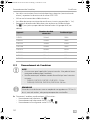
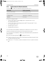
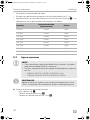
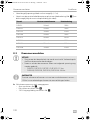
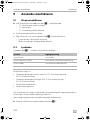
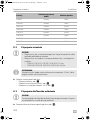
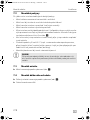
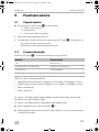
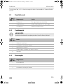
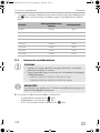
3Scope of delivery
No. in
fig. 1
Designation
1 Sine wave inverter
2 Remote control
3 Connection cable remote control
– Operating manual
DSP600-2000--IO-16s.book Seite 7 Montag, 7. Mai 2018 1:39 13

EN
Target group for this manual SinePower
8
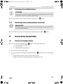
4 Target group for this manual
The electrical installation (chapter “Connecting the inverter” on page 12) is intended
for professionals who are familiar with the applicable regulations of the country in
which the equipment is to be installed and/or used.
All other chapters are intended for the users.
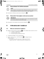
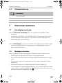
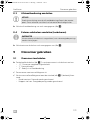
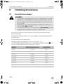
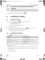
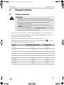
5 Intended use
!
The wave inverter converts direct current into a 230 V AC supply of 50 Hz:
• 12 Vg: DSP612, DSP1012, DSP1512, DSP2012
• 24 Vg: DSP624, DSP1024, DSP1524, DSP2024
6 Technical description
The inverters can be operated wherever a DC connection is available:
• 12 Vg: DSP612, DSP1012, DSP1512, DSP2012
• 24 Vg: DSP624, DSP1024, DSP1524, DSP2024
The light-weight and compact construction of this device allows for easy installation
in mobile homes, commercial vehicles or motor and sailing yachts.
The output voltage corresponds to the household voltage from the socket (pure sine
wave, THD <5 %).
Please observe the values for constant output power and peak output power as
indicated in chapter “Technical data” on page 18. Never connect devices that have
a higher power requirement.
I
WARNING!
Never use the inverter on vehicles where the positive terminal of the
battery is connected to the chassis.
NOTE
Note when connecting devices with an electrical drive (such as power
drills and refrigerators), that they often require more power than is
indicated on the type plate.
DSP600-2000--IO-16s.book Seite 8 Montag, 7. Mai 2018 1:39 13

EN
SinePower Technical description
9
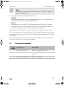
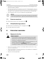
The inverter has various protective mechanisms.
• Overvoltage shutdown: The inverter shuts itself off when the voltage exceeds
the cut-off value. It restarts when the voltage returns to the restart value.
• Undervoltage shutdown: The inverter shuts itself off when the voltage sinks
below the cut-off value. It restarts when the voltage rises to the restart value.
• Excess temperature shutdown: The inverter switches off when the tempera-
ture inside the device or the temperature on the cooling element exceeds a cut-
off value. It restarts when the voltage rises to the restart value.
• Overloading and short circuit shutdown: The LED on the inverter indicates
an operating fault when an excess load is connected or a short circuit has
occurred.
I
The inverter can be operated in the following net configurations:
• TN network:
The neutral conductor of the inverter is grounded. A downstream safety switch
(RCD) must be installed.
• IT network:
Both phases are insulated. This is suitable for operating one load. If more than
one load will be connected a protection plan has to be set up (e. g. insulation
monitor).
The net configuration is set via a DIP switch at the inverter.
The inverter can be switched with the remote control to an energy-saving mode to
prevent the connected battery from discharging too quickly.
Using the remote control, the inverter can be turned on or off and switched to the
energy-saving mode.
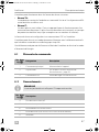
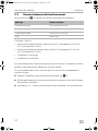
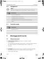
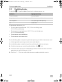
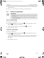
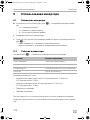
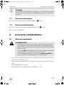
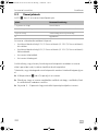
6.1 Control elements
NOTE
The individual values are found in the chapter “Technical data” on
page 18.
No. in
fig. 2
Description Description
1 Main switch Switches the device on or off
2 Status LED See chapter “Status indications” on page 14
3 Dip switch Sets the net configuration
DSP600-2000--IO-16s.book Seite 9 Montag, 7. Mai 2018 1:39 13

EN
Fitting the inverter SinePower
10
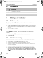
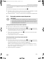
6.2 Connections
I
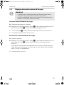
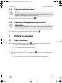
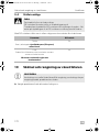
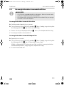
6.3 Remote control
7 Fitting the inverter
7.1 Tools required
For the electrical connection you will need the following tools:
•Crimping tool
• 3multi-coloured, flexible connection cables. Determine the necessary thickness
from the table in chapter “Connecting the inverter” on page 12.
• Cable lugs and conductor sleeves
For fastening you will require the following tools:
• Machine bolts (M4) with washers and self-locking nuts or
• self-tapping screws or wood screws
NOTE
The version for continental Europe is depicted.
No. in
fig. 2
Description
4 AC outlet
5 Remote control connection
6 DC connection
7 Ground terminal (Earthing on the vehicle bodywork)
8Fan
No. in
fig. 3
Description
1 On/off button
2 Status LED
3 Terminal for remote control
DSP600-2000--IO-16s.book Seite 10 Montag, 7. Mai 2018 1:39 13

EN
SinePower Fitting the inverter
11
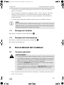
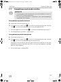
7.2 Mounting instructions
When selecting the installation location, observe the following instructions:
• The inverter can be mounted horizontally or vertically.
• The inverter must be installed in a place that is protected from moisture.
• The inverter may not be installed in the presence of flammable materials.
• The inverter may not be installed in a dusty environment.
• The place of installation must be well ventilated. A ventilation system must be
available for installations in small, enclosed spaces. The minimum clearance
around the inverter must be at least 5 cm (fig. 4).
• The air intake on the back or the air outlet on the front of the inverter must remain
clear.
• For ambient temperatures higher than 40 °C (such as in engine or heating
compartments, or direct sunlight), the inverter may shut down although the
connected load is below the rated load (derating).
• The device must be installed on a level and sufficiently sturdy surface.
A
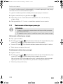
7.3 Mounting the inverter
➤ Mount the inverter as shown (fig. 5).
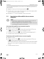
7.4 Mounting the remote control
➤ Mount the remote control as shown (fig. 6).
➤ Remove the protective film.
NOTICE!
Before drilling any holes, make sure that no electrical cables or other
parts of the vehicle can be damaged by drilling, sawing and filing.
DSP600-2000--IO-16s.book Seite 11 Montag, 7. Mai 2018 1:39 13

EN
Connecting the inverter SinePower
12
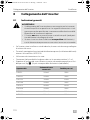
8 Connecting the inverter
8.1 General instructions
!
• When installed in vehicles or boats, the inverter must be connected to the chassis
or earth.
• When setting up a socket distribution circuit (mains setup), comply with the
applicable regulations.
• Only use copper cables.
• Keep the DC cables as short as possible (< 1 m).
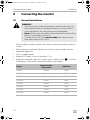
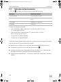
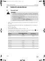
• Keep to the specified cable cross section and fit a cable fuse (fig. 7 1) as close
to the battery as possible on the positive cable (see the table).
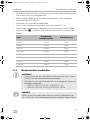
WARNING!
• The inverter may only be connected by a qualified workshop. The
following information is intended for technicians who are familiar
with the guidelines and safety precautions to be applied.
• Never use the inverter on vehicles where the positive terminal of the
battery is connected to the chassis.
• If you do not fit a fuse to the positive cable, the cables can over-
load, which might result in a fire.
Device
Required cable
cross section
Cable fuse
DSP612 25 mm² 150 A
DSP624 25 mm² 150 A
DSP1012 35 mm² 200 A
DSP1024 25 mm² 150 A
DSP1512 50 mm² 250 A
DSP1524 25 mm² 150 A
DSP2012 70 mm² 300 A
DSP2024 35 mm² 200 A
DSP600-2000--IO-16s.book Seite 12 Montag, 7. Mai 2018 1:39 13

EN
SinePower Connecting the inverter
13
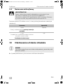
8.2 Connecting the inverter
A
I
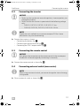
➤ Connect the inverter as shown:
– Connecting the battery: fig. 7
– Connecting the ground terminal fig. 8
– Connecting the 230 V output cable: fig. 9
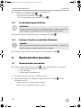
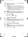
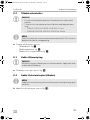
8.3 Connecting the remote control
A
➤ Connect the remote control as shown(fig. 0).
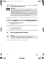
8.4 Connecting external switch (accessories)
I
➤ Close an external switch as shown (fig. a).
NOTICE!
• Make sure that you do not reverse the polarity. Incorrect polarity can
damage the inverter.
• Make sure that the inverter is operated with the following voltage
only:
– DSP612, DSP1012, DSP1512, DSP2012: 12 Vg
– DSP624, DSP1024, DSP1524, DSP2024: 24 Vg
NOTE
Tighten the nuts and bolts to a maximum torque of 15 Nm. Loose
connections may cause overheating.
NOTICE!
Only plug in the connection to the remote control in the remote port.
The device can be damaged by connecting it incorrectly.
NOTE
When using an external switch, you cannot change the status of energy
saving mode.
DSP600-2000--IO-16s.book Seite 13 Montag, 7. Mai 2018 1:39 13

EN
Using the inverter SinePower
14
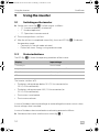
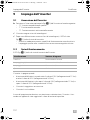
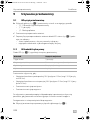
9Using the inverter
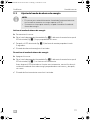
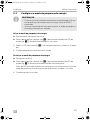
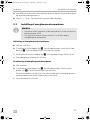
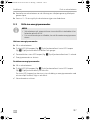
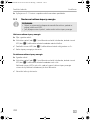
9.1 Switching on the inverter
➤ Set the main switch (fig. 2 1) of the inverter as follows.
– “0”: Inverter completely switched off
– “I”: Standard operation
– “II”: Operation via remote control
✓ The inverter performs a self-test.
✓ After the self-test is completed successfully, the status LED (fig. 2 2) indicates
the operation mode:
– Constantly lit: Normal mode activated
– Flashes four times: Energy-saving mode activated
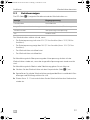
9.2 Status indications
The LED (fig. 2 2) shows the operating condition of the inverter.
The inverter switches off if:
• The battery voltage drops below 10 V (12 Vg connection) or
20 V (24 Vg connection).
• The battery voltage exceeds 16 V (12 Vg connection) or
32 V (24 Vg connection).
• The inverter is overloaded.
• The inverter overheats.
In case of shutdown due to overvoltage or undervoltage the inverter restarts when
the set voltage value is reached.
In case of shutdown due to overload or overheating proceed as follows:
➤ Shut down the inverter with the main switch (fig. 2 1).
Display Input voltage
Constantly lit Normal mode
Long flash, short interruption Inverter overheated/Overload
Quick flash Overvoltage/Undervoltage
Off Other fault
DSP600-2000--IO-16s.book Seite 14 Montag, 7. Mai 2018 1:39 13

EN
SinePower Using the inverter
15
➤ Check that the inverter is sufficiently ventilated and that the ventilation grilles are
unimpeded.
➤ Wait 5 – 10 minutes and switch the inverter on again without any electric
consumers.
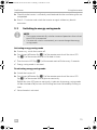
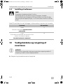
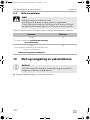
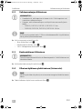
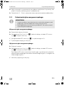
9.3 Switching to energy-saving mode
I
Activating energy saving mode
➤ If necessary, switch the inverter off.
➤ Press the on/off button (fig. 3 1) of the remote control until the status LED
(fig. 3 2) of the remote control has flashed six times.
✓ Then the status LED (fig. 3 2) of the remote control flashes every 5 seconds.
✓ Energy saving mode is activated.
Deactivating energy saving mode
➤ Switch the inverter off.
➤ Press the on/off button (fig. 3 1) of the remote control until the status LED
(fig. 3 2) of the remote control goes on constantly.
Before the status LED goes on constantly, it indicates that energy saving mode
will be switched off by an interval of flashing four times followed by flashing six
times.
✓ Normal mode is activated.
NOTE
• The inverter automatically switches to normal operation when a load
over 45 W is connected.
• If an external switch is connected, you cannot change the energy
saving mode.
DSP600-2000--IO-16s.book Seite 15 Montag, 7. Mai 2018 1:39 13

EN
Cleaning and caring for the inverter SinePower
16
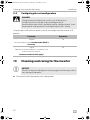
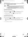
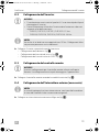
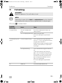
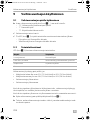
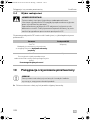
9.4 Configuring the net configuration
D
Using the dip switch you can define in which net configuration the inverter shall
operate.
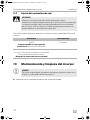
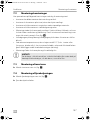
10 Cleaning and caring for the inverter
A
➤ Occasionally clean the product with a damp cloth.
DANGER!
Changing the net configuration results in risk of lethal injury.
The dip switch must only be set by qualified personnel.
Remove the the dip switch‘s protection cap for configuring only. Insert
the protection cap to prevent switching the dip switch‘s setting.
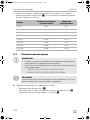
Parameter Dip switch
TN grid
An external downstream circuit breaker (RCD) is
necessary.
On
IT grid
Operation with one load only or installation of an
external insulation monitor.
National standards shall apply!
Off
NOTICE!
Do not use sharp or hard objects or cleaning agents for cleaning as these
may damage the product.
DSP600-2000--IO-16s.book Seite 16 Montag, 7. Mai 2018 1:39 13

EN
SinePower Troubleshooting
17
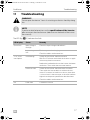
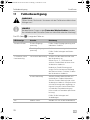
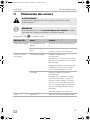
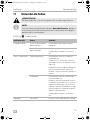
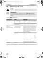
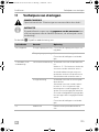
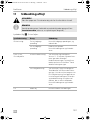
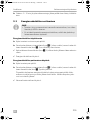
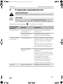
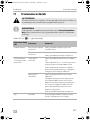
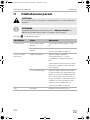
11 Troubleshooting
!
I
The LED (fig. 2 2) indicates the fault:
WARNING!
Do not open the device. You risk sustaining an electric shock by doing
this.
NOTE
If you have detailed questions on the specifications of the inverter
please contact the manufacturer (addresses on the back of the instruc-
tion manual).
LED display Cause Remedy
Quick flash Input voltage is
too high
Check the input voltage and reduce it.
Input voltage too
low
The battery needs recharging.
Check the cables and connections.
2 s lit, short
interruption
Overheating Switch off the inverter and the consumer.
Wait 5 to 10 minutes and switch the inverter on again
without any electric consumers.
Reduce the load and make sure the inverter has better
ventilation. Then switch the consumer back on.
Excessive load Switch off the inverter and remove the consumer.
Then switch the inverter back on without the con-
sumer. If no excessive load is now shown, then there
is a short circuit in the consumer or the total load was
higher than the power specified on the data sheet.
Check the cables and connections.
Off Other fault Contact the service.
DSP600-2000--IO-16s.book Seite 17 Montag, 7. Mai 2018 1:39 13

EN
Warranty SinePower
18
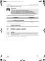
12 Warranty
The statutory warranty period applies. If the product is defective, please contact the
manufacturer's branch in your country (see the back of the instruction manual for the
addresses) or your retailer.
For repair and guarantee processing, please include the following documents when
you send in the device:
• A copy of the receipt with purchasing date
• A reason for the claim or description of the fault
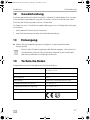
13 Disposal
➤ Place the packaging material in the appropriate recycling waste bins wherever
possible.
M
If you wish to finally dispose of the product, ask your local recycling centre
or specialist dealer for details about how to do this in accordance with the
applicable disposal regulations.
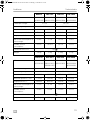
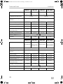
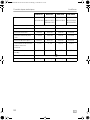
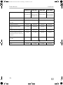
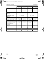
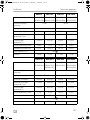
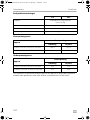
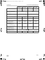
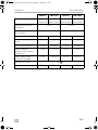
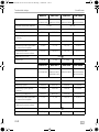
14 Technical data
The following technical data applies to all inverters:
Output voltage: 230 Vw ± 10 %, pure sine wave (THD <5 %)
Output frequency: 50 Hz ± 0,5 Hz
Efficiency: >90 %
Heat dissipation: temperature and load controlled fan
Ambient temperature at operation: 0 °C to +50 °C
Ambient temperature for storage: –30 °C to +70 °C
Air humidity: 0 – 95 %, non-condensing
Testing/certification:
9
DSP600-2000--IO-16s.book Seite 18 Montag, 7. Mai 2018 1:39 13

EN
SinePower Technical data
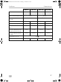
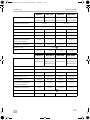
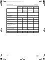
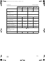
19
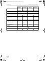
DSP612 DSP 1012 DSP624 DSP 1024
Ref. no.: 9600002543
9600003597
9600002545
9600003599
9600002544
9600003598
9600002546
9600003600
Rated input voltage: 12 V g 24 V g
Input voltage range: 10 – 16.5 Vg 20 – 33 Vg
Rated load: 600 W 1000 W 600 W 1000 W
Maximum power for 1 min: 690 W 1150 W 690 W 1150 W
Surge power for 1 s: 1200 W 2000 W 1200 W 2000 W
Idle current consumption at
rated voltage:
<0.8 A <1.0 A <0.5 A <0.6 A
Standby current
consumption:
<0.3 A <0.35 A <0.2 A <0.2 A
Dimensions W x L x H: fig. e
Weight: 2.8 kg 3.1 kg 2.8 kg 3.1 kg
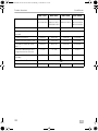
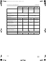
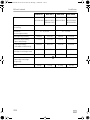
DSP1512 DSP 2012 DSP1524 DSP 2024
Ref. no.: 9600002547
9600003601
9600002549
9600003603
9600002561
9600002548
9600003602
9600002550
9600003604
9600002562
Rated input voltage: 12 V g 24 V g
Input voltage range: 10 – 16.5 Vg 20 – 33 Vg
Rated load: 1500 W 2000 W 1500 W 2000 W
Maximum power for 1 min: 1725 W 2300 W 1725 W 2300 W
Surge power for 1 s: 3000 W 4000 W 3000 W 4000 W
Idle current consumption at
rated voltage:
<1.2 A <1.5 A <0.6 A <0.8 A
Standby current
consumption:
<0.4 A <0.5 A <0.25 A <0.3 A
Dimensions W x L x H: fig. e
Weight: 4.9 kg 5.2 kg 4.9 kg 5.2 kg
DSP600-2000--IO-16s.book Seite 19 Montag, 7. Mai 2018 1:39 13

EN
Technical data SinePower
20
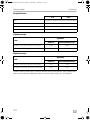
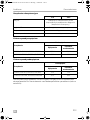
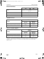
Protective devices
Overvoltage shutdown
Undervoltage shutdown
For the current EU declaration of conformity for your device please refer to the
respective product page on dometic.com or contact the manufacturer directly (see
back page).
12 V 24 V
Input: Undervoltage, reverse polarity (internal fuse)
AC output: Overvoltage, short circuit, overload
Temperature: Shutdown
Short circuit protection: Yes, Ipk
Device
Overvoltage
Shutdown Restart
DSP612, DSP1012, DSP1512, DSP2012 16.5 V 15.5 V
DSP624, DSP1024, DSP1524, DSP2024 33 V 31 V
Device
Undervoltage
Shutdown Restart
DSP612, DSP1012, DSP1512, DSP2012 10 V 12 V
DSP624, DSP1024, DSP1524, DSP2024 20 V 24 V
DSP600-2000--IO-16s.book Seite 20 Montag, 7. Mai 2018 1:39 13
La pagina si sta caricando...
La pagina si sta caricando...
La pagina si sta caricando...
La pagina si sta caricando...
La pagina si sta caricando...
La pagina si sta caricando...
La pagina si sta caricando...
La pagina si sta caricando...
La pagina si sta caricando...
La pagina si sta caricando...
La pagina si sta caricando...
La pagina si sta caricando...
La pagina si sta caricando...
La pagina si sta caricando...
La pagina si sta caricando...
La pagina si sta caricando...
La pagina si sta caricando...
La pagina si sta caricando...
La pagina si sta caricando...
La pagina si sta caricando...
La pagina si sta caricando...
La pagina si sta caricando...
La pagina si sta caricando...
La pagina si sta caricando...
La pagina si sta caricando...
La pagina si sta caricando...
La pagina si sta caricando...
La pagina si sta caricando...
La pagina si sta caricando...
La pagina si sta caricando...
La pagina si sta caricando...
La pagina si sta caricando...
La pagina si sta caricando...
La pagina si sta caricando...
La pagina si sta caricando...
La pagina si sta caricando...
La pagina si sta caricando...
La pagina si sta caricando...
La pagina si sta caricando...
La pagina si sta caricando...
La pagina si sta caricando...
La pagina si sta caricando...
La pagina si sta caricando...
La pagina si sta caricando...
La pagina si sta caricando...
La pagina si sta caricando...
La pagina si sta caricando...
La pagina si sta caricando...
La pagina si sta caricando...
La pagina si sta caricando...
La pagina si sta caricando...
La pagina si sta caricando...
La pagina si sta caricando...
La pagina si sta caricando...
La pagina si sta caricando...
La pagina si sta caricando...
La pagina si sta caricando...
La pagina si sta caricando...
La pagina si sta caricando...
La pagina si sta caricando...
La pagina si sta caricando...
La pagina si sta caricando...
La pagina si sta caricando...
La pagina si sta caricando...
La pagina si sta caricando...
La pagina si sta caricando...
La pagina si sta caricando...
La pagina si sta caricando...
La pagina si sta caricando...
La pagina si sta caricando...
La pagina si sta caricando...
La pagina si sta caricando...
La pagina si sta caricando...
La pagina si sta caricando...
La pagina si sta caricando...
La pagina si sta caricando...
La pagina si sta caricando...
La pagina si sta caricando...
La pagina si sta caricando...
La pagina si sta caricando...
La pagina si sta caricando...
La pagina si sta caricando...
La pagina si sta caricando...
La pagina si sta caricando...
La pagina si sta caricando...
La pagina si sta caricando...
La pagina si sta caricando...
La pagina si sta caricando...
La pagina si sta caricando...
La pagina si sta caricando...
La pagina si sta caricando...
La pagina si sta caricando...
La pagina si sta caricando...
La pagina si sta caricando...
La pagina si sta caricando...
La pagina si sta caricando...
La pagina si sta caricando...
La pagina si sta caricando...
La pagina si sta caricando...
La pagina si sta caricando...
La pagina si sta caricando...
La pagina si sta caricando...
La pagina si sta caricando...
La pagina si sta caricando...
La pagina si sta caricando...
La pagina si sta caricando...
La pagina si sta caricando...
La pagina si sta caricando...
La pagina si sta caricando...
La pagina si sta caricando...
La pagina si sta caricando...
La pagina si sta caricando...
La pagina si sta caricando...
La pagina si sta caricando...
La pagina si sta caricando...
La pagina si sta caricando...
La pagina si sta caricando...
La pagina si sta caricando...
La pagina si sta caricando...
La pagina si sta caricando...
La pagina si sta caricando...
La pagina si sta caricando...
La pagina si sta caricando...
La pagina si sta caricando...
La pagina si sta caricando...
La pagina si sta caricando...
La pagina si sta caricando...
La pagina si sta caricando...
La pagina si sta caricando...
La pagina si sta caricando...
La pagina si sta caricando...
La pagina si sta caricando...
La pagina si sta caricando...
La pagina si sta caricando...
La pagina si sta caricando...
La pagina si sta caricando...
La pagina si sta caricando...
La pagina si sta caricando...
La pagina si sta caricando...
La pagina si sta caricando...
La pagina si sta caricando...
La pagina si sta caricando...
La pagina si sta caricando...
La pagina si sta caricando...
La pagina si sta caricando...
La pagina si sta caricando...
La pagina si sta caricando...
La pagina si sta caricando...
La pagina si sta caricando...
La pagina si sta caricando...
La pagina si sta caricando...
La pagina si sta caricando...
La pagina si sta caricando...
La pagina si sta caricando...
La pagina si sta caricando...
La pagina si sta caricando...
La pagina si sta caricando...
La pagina si sta caricando...
La pagina si sta caricando...
La pagina si sta caricando...
La pagina si sta caricando...
La pagina si sta caricando...
La pagina si sta caricando...
La pagina si sta caricando...
La pagina si sta caricando...
La pagina si sta caricando...
La pagina si sta caricando...
La pagina si sta caricando...
La pagina si sta caricando...
La pagina si sta caricando...
La pagina si sta caricando...
La pagina si sta caricando...
La pagina si sta caricando...
La pagina si sta caricando...
La pagina si sta caricando...
La pagina si sta caricando...
La pagina si sta caricando...
La pagina si sta caricando...
La pagina si sta caricando...
La pagina si sta caricando...
La pagina si sta caricando...
La pagina si sta caricando...
La pagina si sta caricando...
La pagina si sta caricando...
La pagina si sta caricando...
La pagina si sta caricando...
La pagina si sta caricando...
La pagina si sta caricando...
La pagina si sta caricando...
La pagina si sta caricando...
La pagina si sta caricando...
La pagina si sta caricando...
La pagina si sta caricando...
La pagina si sta caricando...
La pagina si sta caricando...
La pagina si sta caricando...
La pagina si sta caricando...
La pagina si sta caricando...
La pagina si sta caricando...
La pagina si sta caricando...
La pagina si sta caricando...
La pagina si sta caricando...
La pagina si sta caricando...
La pagina si sta caricando...
La pagina si sta caricando...
La pagina si sta caricando...
La pagina si sta caricando...
La pagina si sta caricando...
La pagina si sta caricando...
La pagina si sta caricando...
La pagina si sta caricando...
La pagina si sta caricando...
La pagina si sta caricando...
La pagina si sta caricando...
La pagina si sta caricando...
La pagina si sta caricando...
La pagina si sta caricando...
La pagina si sta caricando...
La pagina si sta caricando...
La pagina si sta caricando...
La pagina si sta caricando...
La pagina si sta caricando...
La pagina si sta caricando...
La pagina si sta caricando...
La pagina si sta caricando...
La pagina si sta caricando...
La pagina si sta caricando...
La pagina si sta caricando...
La pagina si sta caricando...
La pagina si sta caricando...
La pagina si sta caricando...
La pagina si sta caricando...
La pagina si sta caricando...
La pagina si sta caricando...
La pagina si sta caricando...
La pagina si sta caricando...
La pagina si sta caricando...
La pagina si sta caricando...
La pagina si sta caricando...
La pagina si sta caricando...
La pagina si sta caricando...
La pagina si sta caricando...
La pagina si sta caricando...
La pagina si sta caricando...
La pagina si sta caricando...
La pagina si sta caricando...
La pagina si sta caricando...
La pagina si sta caricando...
La pagina si sta caricando...
La pagina si sta caricando...
La pagina si sta caricando...
La pagina si sta caricando...
La pagina si sta caricando...
La pagina si sta caricando...
La pagina si sta caricando...
La pagina si sta caricando...
La pagina si sta caricando...
La pagina si sta caricando...
La pagina si sta caricando...
La pagina si sta caricando...
La pagina si sta caricando...
La pagina si sta caricando...
La pagina si sta caricando...
La pagina si sta caricando...
La pagina si sta caricando...
La pagina si sta caricando...
La pagina si sta caricando...
La pagina si sta caricando...
La pagina si sta caricando...
La pagina si sta caricando...
La pagina si sta caricando...
La pagina si sta caricando...
La pagina si sta caricando...
La pagina si sta caricando...
La pagina si sta caricando...
La pagina si sta caricando...
La pagina si sta caricando...
La pagina si sta caricando...
La pagina si sta caricando...
La pagina si sta caricando...
La pagina si sta caricando...
La pagina si sta caricando...
La pagina si sta caricando...
La pagina si sta caricando...
La pagina si sta caricando...
La pagina si sta caricando...
La pagina si sta caricando...
La pagina si sta caricando...
-
 1
1
-
 2
2
-
 3
3
-
 4
4
-
 5
5
-
 6
6
-
 7
7
-
 8
8
-
 9
9
-
 10
10
-
 11
11
-
 12
12
-
 13
13
-
 14
14
-
 15
15
-
 16
16
-
 17
17
-
 18
18
-
 19
19
-
 20
20
-
 21
21
-
 22
22
-
 23
23
-
 24
24
-
 25
25
-
 26
26
-
 27
27
-
 28
28
-
 29
29
-
 30
30
-
 31
31
-
 32
32
-
 33
33
-
 34
34
-
 35
35
-
 36
36
-
 37
37
-
 38
38
-
 39
39
-
 40
40
-
 41
41
-
 42
42
-
 43
43
-
 44
44
-
 45
45
-
 46
46
-
 47
47
-
 48
48
-
 49
49
-
 50
50
-
 51
51
-
 52
52
-
 53
53
-
 54
54
-
 55
55
-
 56
56
-
 57
57
-
 58
58
-
 59
59
-
 60
60
-
 61
61
-
 62
62
-
 63
63
-
 64
64
-
 65
65
-
 66
66
-
 67
67
-
 68
68
-
 69
69
-
 70
70
-
 71
71
-
 72
72
-
 73
73
-
 74
74
-
 75
75
-
 76
76
-
 77
77
-
 78
78
-
 79
79
-
 80
80
-
 81
81
-
 82
82
-
 83
83
-
 84
84
-
 85
85
-
 86
86
-
 87
87
-
 88
88
-
 89
89
-
 90
90
-
 91
91
-
 92
92
-
 93
93
-
 94
94
-
 95
95
-
 96
96
-
 97
97
-
 98
98
-
 99
99
-
 100
100
-
 101
101
-
 102
102
-
 103
103
-
 104
104
-
 105
105
-
 106
106
-
 107
107
-
 108
108
-
 109
109
-
 110
110
-
 111
111
-
 112
112
-
 113
113
-
 114
114
-
 115
115
-
 116
116
-
 117
117
-
 118
118
-
 119
119
-
 120
120
-
 121
121
-
 122
122
-
 123
123
-
 124
124
-
 125
125
-
 126
126
-
 127
127
-
 128
128
-
 129
129
-
 130
130
-
 131
131
-
 132
132
-
 133
133
-
 134
134
-
 135
135
-
 136
136
-
 137
137
-
 138
138
-
 139
139
-
 140
140
-
 141
141
-
 142
142
-
 143
143
-
 144
144
-
 145
145
-
 146
146
-
 147
147
-
 148
148
-
 149
149
-
 150
150
-
 151
151
-
 152
152
-
 153
153
-
 154
154
-
 155
155
-
 156
156
-
 157
157
-
 158
158
-
 159
159
-
 160
160
-
 161
161
-
 162
162
-
 163
163
-
 164
164
-
 165
165
-
 166
166
-
 167
167
-
 168
168
-
 169
169
-
 170
170
-
 171
171
-
 172
172
-
 173
173
-
 174
174
-
 175
175
-
 176
176
-
 177
177
-
 178
178
-
 179
179
-
 180
180
-
 181
181
-
 182
182
-
 183
183
-
 184
184
-
 185
185
-
 186
186
-
 187
187
-
 188
188
-
 189
189
-
 190
190
-
 191
191
-
 192
192
-
 193
193
-
 194
194
-
 195
195
-
 196
196
-
 197
197
-
 198
198
-
 199
199
-
 200
200
-
 201
201
-
 202
202
-
 203
203
-
 204
204
-
 205
205
-
 206
206
-
 207
207
-
 208
208
-
 209
209
-
 210
210
-
 211
211
-
 212
212
-
 213
213
-
 214
214
-
 215
215
-
 216
216
-
 217
217
-
 218
218
-
 219
219
-
 220
220
-
 221
221
-
 222
222
-
 223
223
-
 224
224
-
 225
225
-
 226
226
-
 227
227
-
 228
228
-
 229
229
-
 230
230
-
 231
231
-
 232
232
-
 233
233
-
 234
234
-
 235
235
-
 236
236
-
 237
237
-
 238
238
-
 239
239
-
 240
240
-
 241
241
-
 242
242
-
 243
243
-
 244
244
-
 245
245
-
 246
246
-
 247
247
-
 248
248
-
 249
249
-
 250
250
-
 251
251
-
 252
252
-
 253
253
-
 254
254
-
 255
255
-
 256
256
-
 257
257
-
 258
258
-
 259
259
-
 260
260
-
 261
261
-
 262
262
-
 263
263
-
 264
264
-
 265
265
-
 266
266
-
 267
267
-
 268
268
-
 269
269
-
 270
270
-
 271
271
-
 272
272
-
 273
273
-
 274
274
-
 275
275
-
 276
276
-
 277
277
-
 278
278
-
 279
279
-
 280
280
-
 281
281
-
 282
282
-
 283
283
-
 284
284
-
 285
285
-
 286
286
-
 287
287
-
 288
288
-
 289
289
-
 290
290
-
 291
291
-
 292
292
-
 293
293
-
 294
294
-
 295
295
-
 296
296
-
 297
297
-
 298
298
-
 299
299
-
 300
300
-
 301
301
-
 302
302
-
 303
303
-
 304
304
-
 305
305
-
 306
306
-
 307
307
-
 308
308


Dometic DSP612, DSP624, DSP1012, DSP1024, DSP1512, DSP1524, DSP2012, DSP2024 Istruzioni per l'uso
- Tipo
- Istruzioni per l'uso
in altre lingue
- français: Dometic DSP612, DSP624, DSP1012, DSP1024, DSP1512, DSP1524, DSP2012, DSP2024 Mode d'emploi
- Deutsch: Dometic DSP612, DSP624, DSP1012, DSP1024, DSP1512, DSP1524, DSP2012, DSP2024 Bedienungsanleitung
- slovenčina: Dometic DSP612, DSP624, DSP1012, DSP1024, DSP1512, DSP1524, DSP2012, DSP2024 Návod na používanie
- dansk: Dometic DSP612, DSP624, DSP1012, DSP1024, DSP1512, DSP1524, DSP2012, DSP2024 Betjeningsvejledning
Documenti correlati
-
Dometic SinePower DSP1312T, DSP1324T, DSP1812T, DSP1824T, DSP2312T, DSP2324T, DSP3512T, DSP3524T Guida d'installazione
-
-
-
-
-
Dometic SINEPOWER MSI 224 Istruzioni per l'uso
-
Waeco SP700, SP1000, SP1500, SP2000, SP3000 Istruzioni per l'uso
-
-
-
Altri documenti
-
Telair INVERTER TI SERIES Manuale utente
-
 Peimar PSI-10000TL Guida d'installazione
-
Goodwe GW12KLV-MT Guida d'installazione
-
Goodwe GW5KL-ET Guida d'installazione
-
Goodwe GW2900D-NS Guida d'installazione
-
Goodwe XS Series Grid-Tied PV Inverter Manuale utente
-
Goodwe GW4K-DT Guida d'installazione
-
Goodwe GW250K-HT Guida d'installazione
