
MIXER
Owner’s Manual
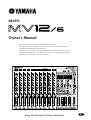
Thank you for purchasing the YAMAHA MV12/6 Mixer.
The MV12/6 mixer is designed to provide the user with an ideal balance of
operability, functionality, and simplicity.
In order to get the most out of your MV12/6 mixer and its functions, and to
enjoy years of trouble-free use, please read this Owner’s Manual thoroughly
and keep it in a safe place for future reference.
Keep This Manual For Future Reference.

MV12/6 — Owner’s Manual
FCC INFORMATION (U.S.A.)
1. IMPORTANT NOTICE: DO NOT MODIFY THIS UNIT! This product, when installed as indicated in the instructions contained in this manual, meets FCC
requirements. Modifications not expressly approved by Yamaha may void your authority, granted by the FCC, to use the product.
2. IMPORTANT: When connecting this product to accessories and/or another product use only high quality shielded cables. Cable/s supplied with this product MUST
be used. Follow all installation instructions. Failure to follow instructions could void your FCC authorization to use this product in the USA.
3. NOTE: This product has been tested and found to comply with the requirements listed in FCC Regulations, Part 15 for Class “B” digital devices. Compliance with
these requirements provides a reasonable level of assurance that your use of this product in a residential environment will not result in harmful interference with
other electronic devices. This equipment generates/uses radio frequencies and, if not installed and used according to the instructions found in the users manual, may
cause interference harmful to the operation of other electronic devices. Compliance with FCC regulations does not guarantee that interference will not occur in all
installations. If this product is found to be the source of interference, which can be determined by turning the unit “OFF” and “ON”, please try to eliminate the
problem by using one of the following measures: Relocate either this product or the device that is being affected by the interference. Utilize power outlets that are on
different branch (circuit breaker or fuse) circuits or install AC line filter/s. In the case of radio or TV interference, relocate/reorient the antenna. If the antenna lead-in
is 300 ohm ribbon lead, change the lead-in to coaxial type cable. If these corrective measures do not produce satisfactory results, please contact the local retailer
authorized to distribute this type of product. If you can not locate the appropriate retailer, please contact Yamaha Corporation of America, Electronic Service
Division, 6600 Orangethorpe Ave, Buena Park, CA 90620
The above statements apply ONLY to those products distributed by Yamaha Corporation of America or its subsidiaries.
WARNING: THIS APPARATUS MUST BE EARTHED
IMPORTANT
THE WIRES IN THIS MAINS LEAD ARE COLOURED IN
ACCORDANCE WITH THE FOLLOWING CODE:
GREEN-AND-YELLOW : EARTH
BLUE : NEUTRAL
BROWN : LIVE
As the colours of the wires in the mains lead of this apparatus may
not correspond with the coloured markings identifying the terminals in
your plug, proceed as follows:
The wire which is coloured GREEN and YELLOW must be
connected to the terminal in the plug which is marked by the letter E
or by the safety earth symbol or coloured GREEN and YELLOW.
The wire which is coloured BLUE must be connected to the terminal
which is marked with the letter N or coloured BLACK.
The wire which is coloured BROWN must be connected to the
terminal which is marked with the letter L or coloured RED.
* This applies only to products distributed by YAMAHA KEMBLE
MUSIC (U.K.) LTD.

MV12/6 — Owner’s Manual
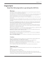
Important
Read the following before operating the MV12/6
Important 1
Warnings
• Do not place a container with liquid or small metal objects on top of this unit. Liquid or metal objects
inside this unit are a fire and electrical shock hazard.
• Do not allow water to enter this unit or allow the unit to become wet. Fire or electrical shock may result.
• Connect this unit’s power cord only to an AC outlet of the type stated in this Owner’s Manual or as
marked on the unit. Failure to do so is a fire and electrical shock hazard.
• Do not scratch, bend, twist, pull, or heat the power cord. A damaged power cord is a fire and electrical
shock hazard.
• Do not place heavy objects, including this unit, on top of the power cord. A damaged power cord is a fire
and electrical shock hazard. In particular, be careful not to place heavy objects on a power cord covered
by a carpet.
• If you notice any abnormality, such as smoke, odor, or noise, or if a foreign object or liquid gets inside
the unit, turn it off immediately. Remove the power cord from the AC outlet. Consult your dealer for
repair. Using the unit in this condition is a fire and electrical shock hazard.
• Should this unit be dropped or the cabinet be damaged, turn the power switch off, remove the power
plug from the AC outlet, and contact your dealer. If you continue using the unit without heeding this
instruction, fire or electrical shock may result.
• If the power cord is damaged (i.e., cut or a bare wire is exposed), ask your dealer for a replacement. Using
the unit with a damaged power cord is a fire and electrical shock hazard.
• Do not remove the unit’s cover. You could receive an electrical shock. If you think internal inspection,
maintenance, or repair is necessary, contact your dealer.
• Do not modify the unit. Doing so is a fire and electrical shock hazard.
• If lightning begins to occur, turn off the power switch of the unit as soon as possible, and unplug the
power cable plug from the electrical outlet.
• If there is a possibility of lightning, do not touch the power cable plug if it is still connected. Doing so
may be an electrical shock hazard.
Cautions
• When rack-mounting the unit, allow enough free space around the unit for normal ventilation. This
should be: 10 cm at the sides, 15 cm behind, and 15 cm above.
For normal ventilation during use, remove the rear of the rack or open a ventilation hole.
If the airflow is not adequate, the unit will heat up inside and may cause a fire.
• Hold the power cord plug when disconnecting it from an AC outlet. Never pull the cord. A damaged
power cord is a potential fire and electrical shock hazard.
• Do not touch the power plug with wet hands. Doing so is a potential electrical shock hazard.
Operating Notes
• Using a mobile telephone near this unit may induce noise. If noise occurs, use the telephone away from
the unit.
• XLR-type connectors are wired as follows:
pin 1: ground, pin 2: hot (+), and pin 3: cold (-).
• The performance of components with moving contacts, such switches, rotary controls, faders, and
connectors, deteriorates over time. The rate of deterioration depends on the operating environment and
is unavoidable. Consult your dealer about replacing defective components.

MV12/6 — Owner’s Manual
2 MV12/6
Features
• The MV12/6 offers 12 input channels that can be mixed into stereo,
monaural, or to four group outputs.
• A MONITOR jack offers easy connection to a sub amp for monitor-
ing. It allows monitoring of the main stereo output, TAPE IN input
and the signals from groups 1-2, 3-4.
• The mixer is equipped with a highly efficient, built-in digital effects
section. The built-in effects allow you to create professional sounding
mixes without the need of additional equipment. An EFFECT SEND
jack is also supplied to allow the use of external effectors.
• Two AUX SEND/RETURN jacks are provided. Two separate AUX
buses can be used as sends for external effectors or a monitor system.
• The mixer supplies phantom power to provide easy connection of
condenser microphones that require an external power source.
• The mixer is equipped with INSERT IN, INSERT OUT jacks for
input channels 1-4 allowing individual effects to be inserted into
individual channels.
• Input Channels 1-8 are equipped with XLR type input jacks. A three-
way selector switch allows compatibility with a wide range of sources
such as condenser microphones that need an external power source,
regular dynamic microphones, line level devices, etc.
Input Channels 9-12 are equipped with stereo line input jacks
• The main input and output jacks are also equipped with Euro-block
connectors. These connectors facilitate the installation of the mixer
as a permanent fixture in halls, etc.
• TAPE IN jacks and REC OUT jacks offer easy connection of tape
decks for playback and recording.
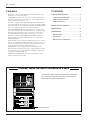
Contents
Front & Rear Panels ............................ 3
Channel Control Section ........................ 3
Master Control Section .......................... 5
Connector Panel .................................... 7
About the Accessories ...................... 11
Applications .......................................... 12
Supplement .......................................... 14
Specifications ....................................... 14
Dimensions .......................................... 16
Block and Level Diagrams .................... 17
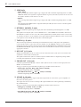
Caution: When the unit is installed in a rack
The main unit’s power switch is located on the rear panel of
the unit. When installed in a rack, please use the external
power switch on a power distributor, etc.
Power distributor, etc.

MV12/6 — Owner’s Manual
Front & Rear Panels 3
q
y
tt
o
u
e
ii
rr
w
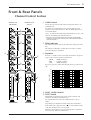
Channels 1-8
(Monaural)
Channels 9-12
(Stereo)
Response [dB]
+5
+10
+15
–15
–10
–5
0
Frequency [Hz]
10k1k100 20k20
+20
–20
Front & Rear Panels
Channel Control Section
q GAIN Control
Adjusts the input level of the signal entering the mixer to an
optimum level.
To obtain an optimum balance between the S/N ratio and
dynamic range, adjust the level so that the PEAK Indicator w
occasionally lights.
-60 to -16 indicates the MIC input adjustment level, -34 to +10
indicates the LINE input adjustment level.
* The Input Select Switch located on the Connector Panel provides
settings for the type of mic or device that is connected to the INPUT
jack (refer to page 7).
w PEAK Indicator
The indicator detects peaks in the signal after it has passed the
EQ.
The indicator will light red when the level reaches +17dB to
warn that clipping is imminent.
e Equalizer
Provides +/-15dB of control over high, mid and low frequency
ranges at the center frequencies listed below.
HIGH : 10kHz (shelving)
MID : 2.5 kHz (peaking)
LOW : 100Hz (shelving)
Frequency response will be flat when the knob is positioned at
“G”.
r AUX1, AUX2 Controls
t POST Switch
Individually controls the level of the signal sent from each
channel to the AUX1 and AUX2 buses.
The signal taken from before the channel fader is sent to
AUX1.
Depending upon the POST switch setting, the signal taken
from either before (POST Switch = ?) or after (POST Switch
= >) the channel fader is sent to AUX2.
When a stereo channel is used, L and R signals are combined
and sent to the AUX1 and AUX2 buses.

MV12/6 — Owner’s Manual
4 Front & Rear Panels
y EFFECT Control
Controls the level of the signal sent from each channel to the EFFECT bus.
This control is located after the channel fader so its level will also be affected by the channel fader
setting.
When a stereo channel is used, L and R channel signals are combined and sent to the EFFECT bus.
u PAN Control (CH1-8)
BAL Control (CH9-12)
The PAN control knobs set the position within the stereo field of each signal that is sent to the GROUP
bus 1-2, GROUP bus 3-4 and STEREO bus L-R.
The BAL control knobs set the balance between left and right channels and assigns the signals that are
received at INPUT L (CH9, 11) to GROUP buses 1/3 or STEREO bus L, and the signals received at
INPUT R (CH10, 12) to GROUP buses 2/4 or STEREO bus R.
i GROUP, ST Select Switches
Used to send the signal of each channel to the GROUP bus 1-2, GROUP bus 3-4 and STEREO bus L-R.
When the switch is ON (>), the signal is sent to the relative bus.
o Channel Fader
Controls the output level of the input channel signal and adjusts the volume balance between channels.
* Levels of unused faders should be lowered.
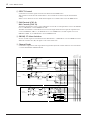
CH INPUT
1~4ch
INPUT
[-60~+10dB]
INSERT OUT
[0dB]
PAD
HA
GAIN
[-60dB~-16dB]
[-34dB~+10dB]
[0dB]
Lo
Mid
Hi
3-Stage EQ
PEAK
Ch.Fader
[-10dB]
BA
[0dB]
[0dB]
1-2
3-4
ST
[-6dB]
PAN
POST
AUX1
AUX2
EFFECT
INSERT IN
[0dB]
MIC(+48V)
MIC
LINE
+48V
BA
CH INPUT
5~8ch
PAD
ST INPUT
9/10ch, 11/12ch
[-34~+10dB]
L
R
HA
HA
[0dB]
GAIN
[-34dB~+10dB]
3-Stage EQ
Lo
Mid
Hi
3-Stage EQ
PEAK
BA
BA
ST Ch.Fader
[-10dB]
[0dB]
SUM
BAL
[0dB]
POST
1-2
3-4
ST
[-6dB]
AUX1
AUX2
EFFECT
STEREO R
EFFECT
STEREO L
GROUP4
GROUP3
GROUP2
GROUP1
AUX1
AUX2
INPUT
[-60~+10dB]
HA
GAIN
[-60dB~-16dB]
[-34dB~+10dB]
MIC(+48V)
MIC
LINE
+48V
[0dB]
Lo
Mid
Hi
3-Stage EQ
PEAK
Ch.Fader
[-10dB]
BA
[0dB]
[0dB]
1-2
3-4
ST
[-6dB]
PAN
POST
AUX1
AUX2
EFFECT

MV12/6 — Owner’s Manual
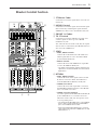
Front & Rear Panels 5
q
i
!5
w
!3
!0
er
!1
!4
!2
t
o
y
u
q ST Master Fader
Controls the level of the signal that is sent to the ST
OUT jacks.
w MONO Control
Controls the level of the signal (the monaural signal
that is formed by combining the signals from the
STEREO bus) that is sent to the MONO OUT jack.
e GROUP 1-4 Faders
r TO ST Switch
Controls the level of the GROUP 1-4 signals, and
sends the signals to their respective GROUP
OUTPUT 1-4 jacks.
Also, when the TO ST switch is ON (>), the signals
whose levels are controlled by the GROUP faders are
also sent to the STEREO bus.
t SEND
• AUX1, AUX2 Controls
Controls the individual levels of the AUX1 and
AUX2 signals that are sent to the AUX1 SEND
jack and AUX2 SEND jack.
• EFFECT Control
Controls the level of the EFFECT bus signal that
is sent to the EFFECT SEND jack.
* This control is not related to, and has no affect on the
signal that is sent from the EFFECT bus to the built-in
digital effects.
y RETURN
• AUX1, AUX2 Controls
Controls the levels of the signals (mixed, L with
R) that are sent to the AUX1 and AUX2 buses
from the RETURN L (MONO) and R jacks.
• GROUP/ST Control
Controls the level of the signal that is sent from
the RETURN L(MONO)/R jacks to the GROUP
buses 1-4 and the stereo bus.
• GROUP, ST Select Switches
Sends the signal from the RETURN L(MONO)/R
jacks to GROUP buses 1-4 and the Stereo bus.
When the switch is ON (>), the signal is sent to
its corresponding buses.
* The signal from the RETURN L jack is sent to GROUP
buses 1 and 3, and the signal from the RETURN R
jack is sent to GROUP buses 2 and 4.
* When only the RETURN L(MONO) jack is used, the
same signal is also sent to the STEREO bus L/R and
GROUP buses 1-4.
Master Control Section

MV12/6 — Owner’s Manual
6 Front & Rear Panels
u DIGITAL EFFECT
• PROGRAM Select Switch
Selects a program from the built-in digital effects.
VOCAL ECHO 1
VOCAL ECHO 2
VOCAL ECHO 3
VOCAL ECHO 4
VOCAL REVERB 1
VOCAL REVERB 2
VOCAL REVERB 3
VOCAL REVERB 4
• PARAMETER Control
Controls parameters (effect level, speed, etc.) of the selected effect program.
• ON Switch
Switches the built-in digital effect ON (>) or OFF (?). When set to OFF, the signal from the built-in
effect is not sent.
• AUX1, AUX2 Control
Controls the level of the signal that is sent from the built-in digital effects to the AUX1 and AUX2 buses.
• GROUP/ST Control
Controls the level of the signal that is sent from the built-in digital effects to GROUP buses 1-4 and the
STEREO bus.
• GROUP, ST Select Switches
Sends the signal from the built-in digital effects to GROUP buses 1-4 and the STEREO bus.
When the switch is ON (>), the signal is sent to its corresponding buses.
i TAPE IN Control
Controls the level of the signal that is sent from the TAPE IN jack to the STEREO bus.
o ST GRAPHIC EQUALIZER
A stereo 7-band graphic equalizer that offers tone adjustment to the signal that is output to the ST OUT
jacks.
A +/-12dB boost or cut is provided at each of the frequency bands 125, 250, 500, 1k, 2k, 4k and 8kHz.
!0 PHONES/MONITOR Output and Meter Select Switch
Selects the signal that is sent to the MONITOR jack, PHONES jack and the level meter.
The three switches are used in combination to select TAPE IN, ST, GROUP 1-2 and GROUP 3-4 signals.
HALL 1
HALL 2
HALL 3
ROOM
PLATE 1
PLATE 2
PLATE 3
GATE REVERB
Signal
Switch
? 1-2 > 3-4 ? ST > GROUP ? > TAPE IN
TAPE IN N/A N/A > TAPE IN
ST N/A ? ST ?
GROUP 1-2 ? 1-2 > GROUP ?
GROUP 3-4 > 3-4 > GROUP ?
!1 PHONES/MONITOR Control
Controls the level of the signal that is sent to the MONITOR jack and PHONES jack.
!2 PHONES Jack
This is a stereo phone type jack for connecting a pair of headphones (nominal output/impedance of
3mW/40Ω). Use the !0 PHONES/MONITOR output and meter select switch to select the source to be
monitored with the headphones.
!3 LEVEL Meter
The LEDs indicate the output level of the signal selected with the PHONES/MONITOR output and Meter
Select Switch !0. “0” indicates a nominal level, and the PEAK indicator will light when clipping is immi-
nent.
!4 POWER Indicator
The indicator will light when the main unit’s power is ON.
!5 LAMP Connector
A XLR type lamp (AC or DC12V, 0.5A Max) can be attached here.
Refer to the Block Diagram on page 17.

MV12/6 — Owner’s Manual
Front & Rear Panels 7
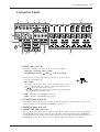
q INPUT Jacks (CH 1-8)
Both balanced XLR type and Euro-block connectors are supplied.
• XLR Type (1:Ground, 2:Hot, 3:Cold)
• Euro-block connectors ( : Hot, : Cold, G: Ground)
Use Input Select Switch to match the input to the type of mic or device
connected to the INPUT jack.
• MIC (+48V)
Allows the connection of condenser mics, etc. Phantom power (DC
+48V) is supplied to the No. 2 and No. 3 pins of the XLR jack and to
the / pins on the Euro-block connector.
* When phantom power is not used, make sure that the Input Select Switch is
set to any position other than MIC (+48V).
• MIC: Compatible with 50-600Ω microphones.
• LINE: Compatible with 600Ω line level devices.
w ST INPUT Jacks (CH 9-12)
Both unbalanced RCA phono type stereo line input jacks and unbalanced Euro-block connectors are
supplied. Both types are compatible with 600Ω line level devices.
e INSERT IN Jacks (CH 1-4)
r INSERT OUT Jacks (CH 1-4)
These are input/output jacks that are positioned between the equalizer and fader of the Input Channel.
The INSERT IN jacks are balanced phone type jacks with a nominal input/impedance of 0dB/600Ω.
The INSERT OUT jacks are impedance balanced phone type jacks with a nominal output/impedance of
0dB/10kΩ. These jacks can be used to connect a graphic equalizer, compressor, noise filter, etc.
Connector Panel
w qo!1!2!0
werty ui
o
!0
!1
!3

MV12/6 — Owner’s Manual
8 Front & Rear Panels
t SEND Jacks
• AUX1, AUX2
These are impedance balanced phone type output jacks with a nominal output/impedance of +4dB/
600Ω. The AUX1, 2 bus signals are output from their respective jacks. These jacks can be used to send
the signal to monitor system such as a cue-box.
• EFFECT
This is an impedance balanced phone type output jack with a nominal output/impedance of +4dB/
600Ω.
The signal from the EFFECT bus is output from this jack. This jack can be used to send the signal to
an external effector, etc.
y RETURN L (MONO), R Jacks
These are unbalanced phone type line input jacks with a nominal input level/impedance of +4dB/
600Ω.
The signal received by this jack is sent to GROUP buses 1-4, the STEREO bus and AUX1, AUX 2 buses.
Normally these jacks are used to receive the return signal from an external effector such as reverb, delay,
etc. but they can also be used as auxiliary stereo inputs. When only the L(MONO) jack is connected, the
same signal is sent to both the R and L jacks as a monaural signal.
u TAPE IN (L, R) Jacks
These are line input jacks for monitoring an external DAT recorder or CD player. The signal that is
received by these jacks is sent to the stereo bus. In this case, the TAPE IN control is used to adjust the
input level. It is also possible to monitor directly from the MONITOR jack or PHONES jack by using
the PHONES/MONITOR output and the Meter Select Switch (Master Control Section) to make the
appropriate selection.
i REC OUT (L, R) Jacks
With an external DAT recorder or cassette recorder connected to these jacks, you can record the same
signal that is sent from the ST OUT jacks.
The signal sent from these jacks is not affected by the ST Mater Fader or Graphic EQ settings. Make
recording level adjustments on the recording device.
o GROUP OUT (1-4) Jacks
Sends the signal from the GROUP 1-4 buses. These jacks are used to connect to the input jack on an
MTR or an external mixer.
Two types of jacks are provided; balanced phone type and Euro-block connectors.
• Phone type (Tip: Hot, Ring: Cold, Sleeve: Ground)
Nominal output/impedance +4dB/600Ω
• Euro-block connector ( : Hot, : Cold, G: Ground)
Nominal output/impedance +4dB/600Ω
!0 ST OUT (L, R) Jacks
These jacks deliver the stereo output of the mixed signal and are connected to a power amplifier, etc.
that drives the main speakers.
The output can also be used for recording of the signal with the level of the signal being controlled by
the ST Master Fader.
Two types of jacks are provided; balanced XLR type and Euro-block connectors.
• XLR type (1: Ground, 2: Hot, 3: Cold)
Nominal output/impedance +4dB/600Ω
• Euro-block connector ( : Hot, : Cold, G: Ground)
Nominal output/impedance +4dB/600Ω

MV12/6 — Owner’s Manual
Front & Rear Panels 9
!1 MONO OUT Jack
This signal is the monaural mix of the STEREO bus’s stereo signal. Its level is controlled with the
MONO control.
Two types of jacks are provided; balanced XLR type and Euro-block connectors.
• XLR type (1: Ground, 2: Hot, 3: Cold)
Nominal output/impedance +4dB/600Ω
• Euro-block connector (
: Hot, : Cold, G: Ground)
Nominal output/impedance +4dB/600Ω
!2 MONITOR (L, R) Jacks
This is an unbalanced Euro-block connector output jack for connecting a monitor system, etc. with a
nominal output/impedance of +4dB/10kΩ.
Use the PHONES/MONITOR output and meter select switch (Master Control Section) to select the
source to be monitored.
!3 POWER Switch
When the switch is in the ON position, the unit is powered.
When turning the power ON, first turn on the mixing console, then turn on the power amp or powered
speakers that are connected to the mixer.
Also, when turning the power OFF, turn off the power amp or powered speakers before turning off the
mixing console.
Connector polarity
INPUT, ST OUT, MONO OUT
Pin 1: ground
Pin 2: hot (+)
Pin 3: cold (–)
INSERT IN, INSERT OUT,
GROUP OUT,
AUX 1/AUX 2/EFFECT SEND
Tip: hot (+)
Ring: cold (–)
Sleeve: ground
PHONES
Tip: L
Ring: R
Sleeve: ground
RETURN
TipSleeve
Ring
TipSleeve
Tip: hot
Sleeve: ground
INPUT OUTPUT

MV12/6 — Owner’s Manual
10 Front & Rear Panels
■ Changing the connector panel’s location.
The mixer allows attachment of the connector panel to either the rear or to the top-side of the mixer to provide
optimum location of the connectors when installing the unit.
The connector panel is attached on the rear of the unit when it is shipped from the factory.
Remove the screws as shown in the illustration to change the location to the top-side.
Please do not perform this operation yourself.
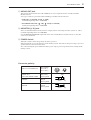
■ Attach a protector cover
Use the nine screw holes located on the control panel to attach a protector cover as shown below.
Please use M4 diameter screws with a length of 12mm or less.
Control Panel
Less than 10mm
M4 Diameter
Less than
12mm
Units: mm
8 190 226 8
128
112.5 56.5
11

MV12/6 — Owner’s Manual
About the Accessories 11
About the Accessories
Euro-block Connectors
If you decide to use Euro-block connectors, please use the supplied connectors and attach as shown in the
illustration below.
q Turn the POWER switch OFF.
w Loosen the screws holding the cover in place and remove the cover.
Euro-block connector
e Attach the Euro-block connectors.
1. If the hole for the wire is closed, turn the screw on the top of the connector to the left to open.
2. Insert the wires according to the jack’s pole display, and turn the upper screw to the right to secure
the wire.
3. Connect the Euro-block connector to the mixer’s jack.
r Replace the cover and re-attach it in its original location.
Caution:
Electric shock may occur if the Euro-block connectors are used without the cover attached.
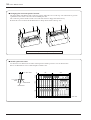
Feet
Four rubber feet are supplied with the mixer.
According to the orientation that the device is installed, attach the rubber feet to the surface that is at the
“bottom” of the mixer.
After wiping any dust and grime on the surface of the mixer, remove the adhesive’s protective cover on the
top of the feet and attach to the mixer.
Secure with a minus (-) driver.

MV12/6 — Owner’s Manual
ST OUT
AUX 1
SEND
AUX 2 (PRE)
SEND
INSERT
IN
INSERT
OUT
PHONES
TAPE IN
REC OUT
INPUT
MONO OUT
12 Applications
Applications
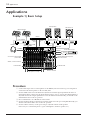
Example 1) Basic Setup
Procedure
q Connect line input devices or microphones to the INPUT jacks and connect a power amp, that is
connected to the main speakers, to the ST OUT Jacks.
w Use the GAIN Control on each channel to adjust the level of the input signal from the device or
microphone that is connected to the input channel (refer to page 3), and use the Channel Fader to
adjust the level of the output signal that is sent to the Master Section. Basically, you should set the
Channel Fader close to the “0” position.
e Press each channel’s “ST” GROUP, ST Select Switch.
r Use the ST Master Fader to adjust the level of the signal sent to the power amplifier. Basically, you
should set the Master Fader close to their “0” position.
t Use the volume control(s) on the power amp to adjust the volume of the speakers.
If necessary, use a monitoring device (a pair of headphones, monitor speakers, etc.).
Microphone, Line Input
GROUP 1-4 Faders
CD Recorder, DAT, etc.
Sub Woofer, etc.
Main Speakers
Power Amplifier Power Amplifier
Effector
ST Master Fader
PHONES/MONITOR Output and
Meter Select Switch
Monitor Speakers
Headphones
Set the POST Switch to “?”
(AUX2=PRE).
GROUP, ST Select Switches
Channel Faders
Power Amplifier

MV12/6 — Owner’s Manual
ST OUT
AUX 1
SEND
AUX 2 (PRE)
SEND
PHONES
TAPE IN
REC OUT
INPUT
GROUP OUT
1
2
3
4
Applications 13
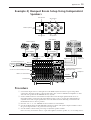
Example 2) Banquet Room Setup Using Independent
Speakers
Procedure
q Connect line input devices or microphones to the INPUT jacks and connect a power amp, that is
connected to the main speakers, to the ST OUT Jacks. Also, connect a 4CH Power Amplifier, etc. that
drives the side speakers to the GROUP OUT (1-4) Jacks.
w Use the GAIN Control on each channel to adjust the level of the input signal from the device or
microphone that is connected to the input channel (refer to page 3), and use the Channel Fader to
adjust the level of the output signal that is sent to the Master Section. Basically, you should set the
Channel Fader close to the “0” position.
e Press the “ST”, “1-2”, “3-4” GROUP, ST Select Switches on each channel.
r Use the ST Master Fader and the GROUP 1-4 Faders to adjust each signal’s output level that is sent to
the power amp. The fader’s “0” position is an average level.
t Use the volume control on the power amp to adjust the speaker’s volume.
If it is necessary, use monitor devices (a pair of headphones, monitor speaker, etc.) or recording devices.
Microphone, Line Input
GROUP 1-4 Faders
Main Speakers
ST Master Fader
PHONES/MONITOR Output and
Meter Select Switch
Monitor Speakers
Headphones
Set the POST Switch to “?” (AUX2=PRE).
GROUP, ST Select Switches
Channel Faders
Power Amplifier
4CH Power
Amplifier, etc.
CD recorder, tape deck, etc.
Power Amplifier
Side Speakers
13
Side Speakers
Side Speakers
24
Main Speaker
L
Main Speaker
R
Monitor Speakers

MV12/6 — Owner’s Manual
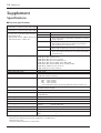
Frequency response 20Hz—20kHz +1dB, -3dB @+4dB, 600Ω (INPUT GAIN Control at minimum level)
Total harmonic distortion <0.1% (THD+N) @+14dB, 20Hz—20kHz, 600Ω
Hum & Noise -128dB Equivalent input noise
-95dB Residual output noise
-64dB (68dB S/N) ST OUT:
Master fader and one channel fader at nominal level, channel
assign switch ON.
-90dB (94dB S/N) ST OUT:
Master fader at nominal level, all channel assign switches
OFF, all GROUP to ST switches OFF.
-90dB (94dB S/N) GROUP OUT:
Master fader at nominal level, all channel assign switches OFF.
-84dB (88dB S/N) AUX SEND, EFFECT SEND:
Master level control at nominal level, all channel send controls
at minimum level.
Maximum voltage gain 60dB INPUT (MIC) to INSERT OUT
84dB INPUT (MIC) to GROUP OUT
84dB INPUT (MIC) to ST OUT (CH to ST)
94dB INPUT (MIC) to ST OUT (GROUP to ST)
76dB INPUT (MIC) to AUX1 SEND, AUX2 SEND (PRE)
86dB INPUT (MIC) to AUX2 SEND (POST) , EFFECT SEND
58dB INPUT (LINE) to ST OUT (CH to ST)
58dB ST INPUT to ST OUT (CH to ST)
Monaural input gain control 44dB variable
Stereo input gain control 44dB variable
Crosstalk at 1kHz -70dB adjacent input
-70dB input to output (CH INPUT)
Input channel equalization ±15dB Maximum
HIGH 10kHz shelving
MID 2.5kHz peaking
LOW 100Hz shelving
* Turn over/Roll off frequency of shelving: 3dB below maximum variable level.
Monaural and stereo input peak indicators Red: Each channel, when the level of the post EQ signal for each channel exceeds
+17dB the indicator will light.
Level meters 12 points LED x2
Graphic equalizer 7 bands (125, 250, 500, 1k, 2k, 4k, 8kHz)
±12dB Maximum
Internal digital effect 16 types
Phantom power +48V (balanced) : Supplied at the Input Select Switch = MIC(+48V) position
Lamp connector XLR type (Lamp Compatibility: AC or DC12V, 0.5A Max)
Power supply/Power consumption USA and Canadian: 120V AC 60Hz, 50W
General: 230V AC 50Hz, 50W
Dimensions (W x H x D) 482 x 308 x 192 mm (7U Rack Mount Size)
Weight 9.0kg
Accessories 3 pin Euro-block connectors: 18
Feet: 4
For European Model 0dB=0.775Vrms
Purchaser/User Information specified in EN55103-1 and EN55103-2.
Inrush Current: 10A
Conformed Environment: E1, E2, E3 and E4
Supplement
Specifications
■ General specifications
14 Supplement
(Rs=150Ω, 20Hz—20kHz, INPUT GAIN Control=Max.,
Input Sensitivity=-60dB)
* Measured with 12.7kHz, -6dB/oct. low pass filter.
(Equivalent to 20kHz, -
∞
dB/oct. filter.)
(CH MIC INPUT to ST, GROUP OUT/AUX, EFFECT SEND)
(CH MIC INPUT to ST, GROUP OUT/AUX, EFFECT SEND)

MV12/6 — Owner’s Manual
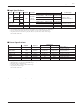
Supplement 15
■ Input Specifications
Input
Input
GAIN Input Nominal
Input level
Connector type
connectors
Select Switch
Control impedance impedance
Sensitivity *1 Nominal
Max. before clipping
MIC (+48V)
-60 -80 dB (0.078mV) -60 dB (0.775mV) -40 dB (7.75mV)
MIC
50-600Ω
INPUT
LINE -34
3kΩ mics &
-54 dB (1.55mV) -34 dB (15.5mV) -14 dB (155mV)
XLR-3-31 type *2
(1-8)
MIC (+48V)
-16
600Ω lines
-36 dB (12.3mV) -16 dB (123mV) +4 dB (1.23V)
Euro-block connector *2
MIC
LINE +10 -10 dB (245mV) +10 dB (2.45V) +30 dB (24.5V)
ST INPUT (L, R)
-34
10kΩ 600Ω lines
-54 dB (1.55mV) -34 dB (15.5mV) -14 dB (155mV)
RCA phono jack *3
(9/10, 11/12)
+10 -10 dB (245mV) +10 dB (2.45V) +30 dB (24.5V)
Euro-block connector *3
RETURN (L, R) 10kΩ 600Ω lines -12 dB (195mV) +4 dB (1.23V) +20 dB (7.75V) Phone jack (TRS) *3
TAPE IN (L, R) 10kΩ 600Ω lines -26 dBV (50.1mV) -10 dBV (316mV) +10 dBV (3.16V) RCA phono jack *3
INSERT IN (1-4) 10kΩ 600Ω lines -20 dB (77.5mV) 0 dB (0.775V) +20 dB (7.75V) Phone jack (TRS) *2
*1 Input sensitivity: the lowest level that will produce the nominal output level when the unit is set to maximum gain.
*2 XLR type connector, Euro-block connector, phone jack (TRS) (T=Hot, R=Cold, S=Gnd): balanced type.
*3 RCA phono jack, Euro-block connector, phone jack (TRS) (T=Signal, R= Gnd, S=Gnd): unbalanced type.
• 0dB=0.775Vrms, 0dBV=1Vrms
■ Output Specifications
Output connectors
Output Nominal
Output level
Connector type
impedance impedance
Nominal
Max. before clipping
ST OUT (L, R), MONO OUT 150Ω 600Ω lines +4 dB (1.23V) +24 dB (12.3V)
XLR-3-32 type *1
Euro-block connector *1
AUX SEND (1, 2)
75Ω 600Ω lines +4 dB (1.23V) +20 dB (7.75V) Phone jack (TRS) *2
EFFECT SEND
GROUP OUT (1-4) 150Ω 600Ω lines +4 dB (1.23V) +24 dB (12.3V)
Phone jack (TRS) *3
Euro-block connector *1
MONITOR (L, R) 470Ω 10kΩ lines +4 dB (1.23V) +20 dB (7.75V) Euro-block connector *4
INSERT OUT (1-4) 600Ω 10kΩ lines 0 dB (0.775V) +20 dB (7.75V) Phone jack (TRS) *2
PHONES 100Ω 40Ω phones 3mW 75mW ST phone jack (TRS) *5
REC OUT (L, R) 600Ω 10kΩ lines -10 dBV (316mV) +10 dBV (3.16V) RCA phono jack *6
*1 XLR type connector, Euro-block connector: balanced type.
*2 Phone jack (TRS) (T=Hot, R=Cold, S=Gnd): impedance balanced type.
*3 Phone jack (TRS) (T=Hot, R=Cold, S=Gnd): balanced type.
*4 Euro-block connector: unbalanced type.
*5 ST phone jack (TRS) (T=L, R=R, S=Gnd): unbalanced type.
*6 RCA phono jack: unbalanced type.
• 0dB=0.775Vrms, 0dBV=1Vrms
Specifications are subject to change without prior notice.

MV12/6 — Owner’s Manual
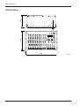
16 Supplement
192308
482
18.7
Units: mm
Dimensions

MV12/6 — Owner’s Manual
Supplement 17
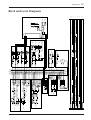
CH INPUT
1~4ch
INPUT
[-60~+10dB]
INSERT OUT
[0dB]
PAD
HA
GAIN
[-60dB~-16dB]
[-34dB~+10dB]
[0dB]
Lo
Mid
Hi
3-Stage EQ
PEAK
Ch.Fader
[-10dB]
BA
[0dB]
[0dB]
1-2
3-4
ST
[-6dB]
PAN
POST
AUX1
AUX2
EFFECT
INSERT IN
[0dB]
MIC(+48V)
MIC
LINE
+48V
BA
CH INPUT
5~8ch
PAD
ST INPUT
9/10ch, 11/12ch
[-34~+10dB]
L
R
HA
HA
[0dB]
GAIN
[-34dB~+10dB]
3-Stage EQ
Lo
Mid
Hi
3-Stage EQ
PEAK
BA
BA
ST Ch.Fader
[-10dB]
[0dB]
SUM
BAL
[0dB]
POST
1-2
3-4
ST
[-6dB]
AUX1
AUX2
EFFECT
TAPE IN
[-10dBV]
L
R
BA
BA
[0dB]
[-6dB]
TAPE IN
RETURN
[+4dB]
L/MONO
R
BA
BA
[+4dB]
[-2dB]
AUX2
GROUP/ST
AUX1
[0dB]
DIGITAL
EFFECT
ON
[-6dB]
AUX2
GROUP/ST
AUX1
STEREO R
EFFECT
STEREO L
GROUP4
GROUP3
GROUP2
GROUP1
AUX1
AUX2
STEREO R
EFFECT
STEREO L
GROUP4
GROUP3
GROUP2
GROUP1
AUX1
AUX2
GROUP1 Fader
[0dB]
BA
BA
BA
BA
SUM
SUM
SUM
SUM
[0dB]
[0dB]
[0dB]
[0dB]
[0dB]
[-10dB]
GROUP2 Fader
[-10dB]
GROUP3 Fader
[-10dB]
GROUP4 Fader
[-10dB]
GROUP OUT 1
[+4dB]
GROUP OUT 2
[+4dB]
GROUP OUT 3
[+4dB]
GROUP OUT 4
[+4dB]
SUM
SUM
INV
INV
[0dB]
[0dB]
BA
BA
ST Master
Fader
[-10dB]
BA
SUM
REC OUT
[-10dBV]
R
L
GEQ
GEQ
ST OUT L
[+4dB]
ST OUT R
[+4dB]
MONO OUT
[+4dB]
SUM
SUM
[0dB]
[0dB]
AUX1 SEND
[+4dB]
AUX2 SEND
[+4dB]
AUX1
[-6dB]
AUX2
[-6dB]
INV
INV
SUM
INV
EFFECT
[-6dB]
PROGRAM
PARAMETER
DIGITAL
EFFECT
(INV)
LO
RO
[0dB]
IN
G1-2/G3-4
ST/GROUP
TAPE IN
PHONES/
MONITOR
[-16dB]
BA
BA
PHONES
[3mW@40ohms]
LEVEL Meters(LED)
PEAK
PEAK
TO ST
TO ST
INPUT
[-60~+10dB]
HA
GAIN
[-60dB~-16dB]
[-34dB~+10dB]
MIC(+48V)
MIC
LINE
+48V
[0dB]
Lo
Mid
Hi
3-Stage EQ
PEAK
Ch.Fader
[-10dB]
BA
[0dB]
[0dB]
1-2
3-4
ST
[-6dB]
PAN
POST
AUX1
AUX2
EFFECT
1-2
3-4
ST
1-2
3-4
ST
MONITOR
[+4dB]
[+4dB]
EFFECT SEND
[+4dB]
DR
DR
[-6dB]
MONO
+30dB +30dB
+20dB +20dB
+10dB +10dB
0dB 0dB
-10dB –10dB
-20dB –20dB
-30dB –30dB
-40dB –40dB
-50dB –50dB
-60dB –60dB
INPUT(LINE)
GAIN Min.[+10dB]
INPUT(MIC)
GAIN Min.[-16dB]
INPUT(LINE)
GAIN Max.[-34dB]
INPUT(MIC)
GAIN Max.[-60dB]
ST INPUT
GAIN Min.[+10dB]
ST INPUT
GAIN Min.[+10dB]
ST INPUT
GAIN Max.[-34dB]
Max. Before Clip
INSERT IN [0dB]
Max. Before Clip
TAPE IN [-10dBV]
Channel
Fader
RETURN [+4dB]
CH & ST INPUT to GROUP/STEREO [0dB]
RETURN to AUX/GROUP/STEREO [-2dB]
TAPE IN to STEREO [-6dB]
DSP to AUX/GROUP/STEREO [-6dB]
Max. Before Clip
AUX SEND [+4dB]
EFFECT SEND [+4dB]
AUX
EFFECT
Control
Master
GROUP
Fader
Master
Max. Before Clip
GROUP OUT [+4dB]
REC OUT [-10dBV]
ST
Fader
Master
Max. Before Clip
ST OUT, MONO OUT [+4dB]
PHONES/MONITOR
MONITOR [+4dB]
PHONES [3mW@40ohms]
INSERT OUT [0dB]
MONO Master
Control
CH & ST INPUT to AUX/EFFECT [-6dB]
Block and Level Diagrams

YAMAHA CORPORATION
Pro Audio & Digital Musical Instrument Division
P.O. Box 3, Hamamatsu, 430-8651, Japan
V639260 R2 1 CP 20
NP Printed in Taiwan
-
 1
1
-
 2
2
-
 3
3
-
 4
4
-
 5
5
-
 6
6
-
 7
7
-
 8
8
-
 9
9
-
 10
10
-
 11
11
-
 12
12
-
 13
13
-
 14
14
-
 15
15
-
 16
16
-
 17
17
-
 18
18
-
 19
19
-
 20
20


Yamaha MV12 Manuale utente
- Categoria
- Mixer audio
- Tipo
- Manuale utente
in altre lingue
- English: Yamaha MV12 User manual
- français: Yamaha MV12 Manuel utilisateur
- español: Yamaha MV12 Manual de usuario
- Deutsch: Yamaha MV12 Benutzerhandbuch
- русский: Yamaha MV12 Руководство пользователя
- Nederlands: Yamaha MV12 Handleiding
- português: Yamaha MV12 Manual do usuário
- dansk: Yamaha MV12 Brugermanual
- čeština: Yamaha MV12 Uživatelský manuál
- polski: Yamaha MV12 Instrukcja obsługi
- svenska: Yamaha MV12 Användarmanual
- Türkçe: Yamaha MV12 Kullanım kılavuzu
- română: Yamaha MV12 Manual de utilizare
Documenti correlati
-
Yamaha EMX5000 Manuale utente
-
-
-
-
-
-
-
-
-