
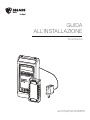
INSTALLATION
GUIDE
SmartSense
For help, call 1-877-BIG-FANS
or visit www.bigassfans.com
Manuel d’Installation
Guía de instalación
Installationsanleitung
Guida all’installazione

Installation Guide
July 2017
Rev. N
Original English Instructions
This product was manufactured in a plant whose Management System is certified as being in conformity with ISO 9001.
Legal
Improper installation, delivery, or maintenance, including, but not limited to, any of the following actions by the customer or agent of the
customer will constitute a breach of and will void all warranties:
• Failure to follow the required installation procedures specified in this Installation Guide and in all other documentation supplied with
the fans and related equipment including documentation provided by the manufacturers of the individual fan and control components;
• Failure to follow all relevant codes and ordinances, including, but not limited to, the National Electric Code (United States), applicable
national and local electrical codes, and state and local building codes;
• Failure to follow electrical engineering industry standards regarding the approved method of installing solid-state electrical equipment
having the characteristics of the fans, the fan controls, and their related components, even if such standards are not specifically
referenced in any instructions or literature supplied by Big Ass Solutions or provided by manufacturers.
SmartSense is a trademark of Delta T Corporation. All other trademarks used herein are the properties of their respective owners. No part
of this document may be reproduced or translated into a dierent language without the prior written consent of Big Ass Solutions. The
information contained in this document is subject to change without notice. For the most up-to-date information, see the online installation
guide at www.bigassfans.com.
www.bigasssolutions.com/patents ▪ www.bigasssolutions.com/warranties
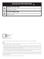
READ AND SAVE THESE INSTRUCTIONS
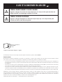
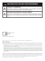
WARNING AND CAUTION SYMBOL
Indicates a hazard with a medium level of risk that could result in injury or death or damage
to property if not avoided
ELECTRICAL WARNING SYMBOL
Indicates an electrical hazard with a medium level of risk that could result in death or serious
injury if not avoided

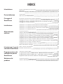
CONTENTS
Introduction
Important Safety Instructions ii
Technical Specifications 1
Dimensions 1
Pre-Installation
Parts 2
Power Cord Plugs 2
Mounting
SmartSense
SmartSense Overview
Mount the Upper Temperature Sensor (to I-Beam) 4
Mount the Upper Temperature Sensor (to Wood Beam) 5
Mount the Wall Controller 6
Installation
SmartSense With Powerfoil
®
X2.0 and Powerfoil
®
X2.0Plus Fans 7
SmartSense With Powerfoil
®
X3.0 and Powerfoil
®
X3.0Plus Fans 8
SmartSense With Basic 6
®
, Powerfoil
®
8, and Powerfoil
®
8Plus Fans 9
SmartSense With Essence
®
Fans 10
Electrical Installation
Wall Controller 11
Upper Temperature Sensor 11
Single Fan Installation for Powerfoil
®
X2.0 and Powerfoil
®
X2.0Plus Fans 12
MultiFan Installation (Daisy Chaining) for Powerfoil
®
X2.0 and
Powerfoil
®
X2.0Plus Fans 13
Single Fan Installation for Powerfoil
®
X3.0 and Powerfoil
®
X3.0Plus Fans 14
MultiFan Installation (Daisy Chaining) for Powerfoil
®
X3.0 and
Powerfoil
®
X3.0Plus Fans 15
Single Fan Installation for Basic 6
®
, Powerfoil
®
8, and Powerfoil
®
8Plus Fans 16
MultiFan Installation (Daisy Chaining) for Basic 6
®
, Powerfoil
®
8, and
Powerfoil
®
8Plus Fans 17
Single Fan Installation for Essence
®
Fans 18
MultiFan Installation (Daisy Chaining) for Essence® Fans 20
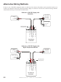
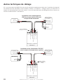
Alternative Wiring Methods 22
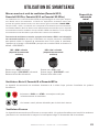
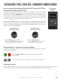
Operating the
SmartSense
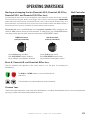
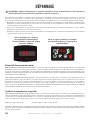
Starting and Stopping the Fan 23
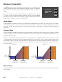
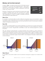
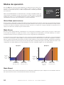
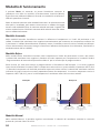
Modes of Operation 24
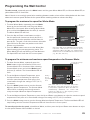
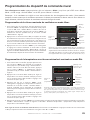
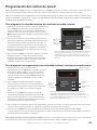
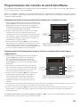
Programming the
SmartSense
Selecting a Mode 25
Programming Winter Mode Maximum Fan Speed 25
Programming Summer Mode Minimum and Maximum Temperatures 25
Adjusting Manual Mode Fan Speed 25
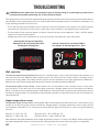
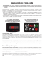
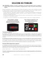
Troubleshooting
Wall Controller 26
Upper Temperature Sensor 26

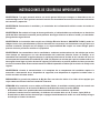
IMPORTANT SAFETY INSTRUCTIONS
WARNING: This guide is intended to provide a basic overview for integrating a SmartSense with a Big Ass
Fan. Consult the Installation Guide included with the fan for additional installation and operation instructions.
WARNING: Disconnect fan and controller from power supply before installing the SmartSense.
WARNING: To reduce the risk of electric shock, wiring should be performed by a qualified electrician! Incorrect
assembly can cause electric shock or damage the motor and the controller! Hazard of electrical shock!
WARNING: Installation must be in accordance with the National Electrical Code, ANSI/NFPA 70-2011, and all
local codes. The procedures and techniques outlined in this manual are merely a guide for proper installation.
Code compliance is your responsibility! Failure to comply with these codes could result in personal injury or
property damage.
WARNING: The fan controllers contain high voltage capacitors which take time to discharge after removal of
mains supply. Before working on the fan controller, ensure isolation of mains supply from line inputs at the
fan controller’s disconnect (L1, L2/N, L3). Wait three minutes for capacitors to discharge to safe voltage levels.
Failure to do so may result in personal injury or death. Note: Darkened display LEDs are not an indication of
safe voltage levels.
WARNING: When service or replacement of a fan component requires the removal or disconnection of a safety
device, the safety device is to be reinstalled or remounted as previously installed.
CAUTION: The Big Ass Fans product warranty will not cover equipment damage or failure that is caused by
improper installation.
ATTENTION: If installing the fan in the United States, the fan must be installed per the following National Fire
Protection Association (NFPA) guidelines:
• The fan must be centered approximately between four adjacent sprinklers.
• The vertical distance from the fan to the sprinkler deflector must be at least 3 ft (91.4 cm).
• The fan must be interlocked to shut down immediately upon receiving a waterflow signal from the alarm
system.

WWW.BIGASSSOLUTIONS.COM © 2015 DELTA T CORP. ALL RIGHTS RESERVED.
1
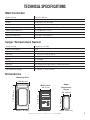
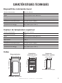
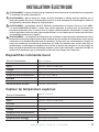
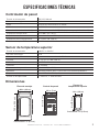
TECHNICAL SPECIFICATIONS
Wall Controller
Supply voltage +24 VDC, 100 mA
Power consumption ≤ 1 W
Output 4–20 mA DC current loop
Wiring 18–22 AWG
Max wiring distance (ft) ((Vsupply-10 V)/0.02 A) / (Wire Ohms per Foot x 2)
Operating temperature 32° to 100°F (0° to 38°C)
Humidity 95% Relative humidity. Board is conformal coated
Storage temperature 14° to 122° F (-10° to 50° C)
ESD withstand voltage +/- 4 kV Air, +/- 4 kV Contact
Upper Temperature Sensor
Supply voltage +10 VDC to +24 VDC
Power consumption ≤ 1 W
Output 4–20 mA DC current loop
Accuracy +/- 1° @ 77° F (+/- 0.5° @ 25° C)
Non-linearity +/- 0.5° F
Wiring 18–22 AWG
Operating temperature 32° to 100° F (0° to 38° C)
Humidity 95% Relative humidity. Board is conformal coated.
Storage temperature 14° to 122° F (-10° to 50° C)
ESD withstand voltage +/- 4 kV Air, +/- 4 kV Contact
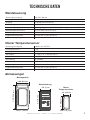
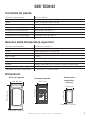
Dimensions
Wall Control
5.1” (13 cm)
2.8” (7 cm)
Depth: 1" (2.5 cm)
Mounting Plate
3.86” (9.8 cm)
7.25” (18.4 cm)
Upper
Temperature
Sensor
Depth: 1" (2.5 cm)
4” (10.2 cm)
1.9” (4.8 cm)

WWW.BIGASSSOLUTIONS.COM © 2015 DELTA T CORP. ALL RIGHTS RESERVED.
2
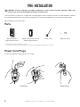
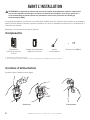
PRE-INSTALLATION
CAUTION: The wall controller and upper temperature sensor contain sensitive electronic PCBs. Use
extreme care when handling! ESD precautions recommended.
The SmartSense is shipped in a single box and packaged in static shielding materials for ESD protection. Review
the information below to ensure you have received all necessary components for installation and operation.
Note: Drawings are not to scale.
Parts
Wall Controller &
Mounting Hardware
Upper Temperature Sensor
& Mounting Hardware
Power Cord
1
500 Resistor
2
1. Install the appropriate plug type for your region.
2. The resistor is needed only for 0–10 V devices controlled by a 4–20 mA analog signal when connected.
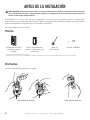
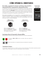
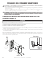
Power Cord Plugs
Install the appropriate plug type for your region.
Install plug Remove plug

WWW.BIGASSSOLUTIONS.COM © 2015 DELTA T CORP. ALL RIGHTS RESERVED.
3
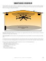
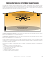
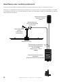
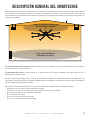
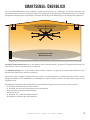
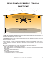
SMARTSENSE OVERVIEW
The SmartSense wall control relies on air temperature readings at the locations of the wall controller and upper
temperature sensor. Proper mounting locations are essential to the successful adjustment of the room temperature.
Refer to the diagram and guidelines below.
Upper Temperature Sensor
mounting location
Wall Controller mounting
location
The upper temperature sensor must be mounted in the upper portion of the zone in order to obtain an accurate
temperature reading at the ceiling level.
The wall controller must be mounted in the lower portion of the zone to obtain an accurate reading at the floor
level.
Install the wall controller and upper temperature sensor on flat surfaces that are free from vibration and where there
is adequate distance from foreign objects or moving equipment. The wall controller should be readily accessible.
Do not mount the wall controller or upper temperature sensor in the following locations:
• Adjacent to or above radiant heaters
• Near HVAC ventilation intakes or exhausts
• On poorly insulated exterior walls
• In roof decking
• Near radiant heat sources
• In an area outside of the fan zone

WWW.BIGASSSOLUTIONS.COM © 2015 DELTA T CORP. ALL RIGHTS RESERVED.
4
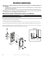
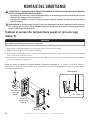
MOUNTING SMARTSENSE
WARNING—TO REDUCE THE RISK OF FIRE, ELECTRIC SHOCK, OR INJURY TO PERSONS, OBSERVE THE
FOLLOWING:
• Installation work and electrical wiring must be done by qualified person(s) in accordance with all
applicable codes and standards.
• When cutting or drilling into a wall or ceiling, do not damage electrical wiring or other hidden utilities.
CAUTION: The wall controller and upper temperature sensor contain sensitive electronic PCBs. Use
extreme care when handling! ESD precautions recommended.
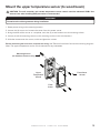
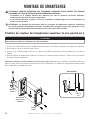
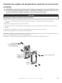
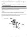
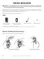
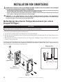
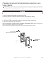
Mount the upper temperature sensor (to I-Beam)
ATTENTION
Do not lose the rubber grommet during installation.
1. Route power wiring to the mounting location.
2. Loosen the (4) screws and remove the front cover.
3. Insert pan head screw (a) through the mounting hole and secure i-beam clamp (b) to the back of the sensor.
4. Mount the upper temperature sensor to the i-beam as shown. Tighten i-beam clamp until securely mounted.
Before reattaching the front cover, complete the wiring. See "Electrical Installation" for details and wiring diagrams.
Note: The upper temperature sensor can be mounted in any orientation.
c
b
I-beam
Side View
Front
Cover
Upper
Temperature
Sensor
I-beam
Clamp
a

WWW.BIGASSSOLUTIONS.COM © 2015 DELTA T CORP. ALL RIGHTS RESERVED.
5
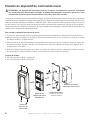
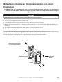
Mount the upper temperature sensor (to wood beam)
CAUTION: The wall controller and remote temperature sensor contain sensitive electronic PCBs. Use
extreme care when handling! ESD precautions recommended.
ATTENTION
Do not lose the rubber grommet during installation.
1. Route power wiring to the mounting location.
2. Loosen the (4) screws and remove the cover from the remote sensor.
3. Using the back of the sensor as a template, mark the (2) screw locations on the mounting surface.
4. Loosely install the mounting screws on the mounting surface in the hole locations.
5. Slide the remote over the screws, and then tighten the screws.
Before reattaching the front cover, complete the wiring. See "Electrical Installation" for details and wiring diagrams.
Note: The upper temperature sensor can be mounted in any orientation.
Front
Cover
Upper
Temperature
Sensor
Front Cover
Screws
Mounting Screws
(for wooden structures only)

WWW.BIGASSSOLUTIONS.COM © 2015 DELTA T CORP. ALL RIGHTS RESERVED.
6
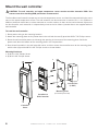
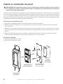
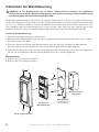
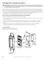
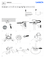
Mount the wall controller
CAUTION: The wall controller and upper temperature sensor contain sensitive electronic PCBs. Use
extreme care when handling! ESD precautions recommended.
The SmartSense wall control incorporates an internal temperature sensor and should be mounted within the same
zone as the upper temperature sensor. The wall controller can be mounted to a standard 2 in. x 4 in. (5.08 cm x
10.16 cm) electrical switch box or surface-mounted on a wall or column. It does not have to be located adjacent to
the fan controller; each controller is independently wired to the fan. Note: A junction box is not supplied with the
wall controller.
To install the wall controller:
1. Route power wiring to the mounting location.
2. Attach the mounting plate to the junction box in the wall with the two (2) provided 6-32 x 7/8” Phillips screws.
3. Route the wall controller power cord through the opening in the center of the mounting plate. Guide the
power cord down the bottom of the mounting plate in the slot provided.
4. Rest the wall controller in the wall controller cover, and then secure the controller cover to the mounting plate
with the four (4) provided 6-32 x 3/8” Phillips screws as shown below.
Mounting Hardware:
a. (2) 6-32 x 1-1/4” Phillips Screw
b. (4) 6-32 x 3/8” Phillips Screw
a
b
Junction Box
(in Wall)
SmartSense
Wall Controller
Mounting Plate
(fits standard junction box)
Controller
Cover

WWW.BIGASSSOLUTIONS.COM © 2015 DELTA T CORP. ALL RIGHTS RESERVED.
7
PU
RUN STOP FWD RE V RE M LOC
U
H
MODE
PROG
DATA
FWD
REV
RUN
STOP
RE SET
LOCAL
REM
F
MODE
FAN SPEED
THRESHOLD TEMPERATURE
10%
55°F
100%
100°F
WINTER MODE
SUMMER MODE
MANUAL
SmartSense Wall Controller
(mounting plate not shown)
Ceiling-mounted Upper
Temperature Sensor
PowerfoilX2.0 or
PowerfoilX2.0Plus Fan System
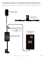
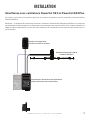
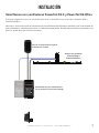
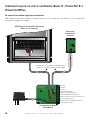
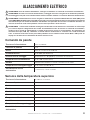
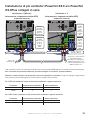
INSTALLATION
SmartSense with Powerfoil
®
X2.0 and Powerfoil
X2.0Plus fans
Refer to the diagram below for the general installation of a SmartSense with Powerfoil
X2.0 and Powerfoil
X2.0Plus
fans.
Note: The Powerfoil X2.0/Powerfoil X2.0Plus wall controller and the SmartSense wall controller do not have to
be mounted adjacent to one other; each device is wired independently. Wiring for both wall controllers can be
routed in the same conduit.

WWW.BIGASSSOLUTIONS.COM © 2015 DELTA T CORP. ALL RIGHTS RESERVED.
8
PU
RUN S TOP FWD R EV RE M LOC
U
H
MODE
PROG
DATA
FWD
RE V
RUN
STOP
RE SET
LOCAL
RE M
F
MODE
FAN SPEED
THRESHOLD TEMPERATURE
10%
55°F
100%
100°F
WINTER MODE
SUMMER MODE
MANUAL
SmartSense Wall Controller
(mounting plate not shown)
Ceiling-mounted Upper
Temperature Sensor
PowerfoilX3.0 or
PowerfoilX3.0Plus Fan System
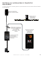
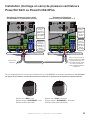
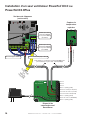
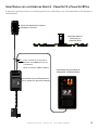
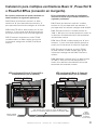
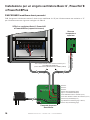
SmartSense with Powerfoil
®
X3.0 and Powerfoil
®
X3.0Plus fans
Refer to the diagram below for the general installation of a SmartSense with Powerfoil
®
X3.0 and Powerfoil
®
X3.0Plus
fans.
Note: The PowerfoilX3.0/PowerfoilX3.0Plus fan auxiliary controller and the SmartSense wall controller do not
have to be mounted adjacent to one other; each device is wired independently. Wiring for both controllers can
be routed in the same conduit.

WWW.BIGASSSOLUTIONS.COM © 2015 DELTA T CORP. ALL RIGHTS RESERVED.
9
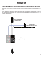
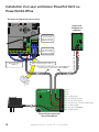
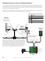
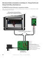
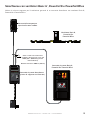
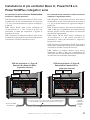
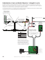
SmartSense with Basic 6
®
, Powerfoil
®
8, and Powerfoil
®
8Plus fans
Refer to the diagram below for the general installation of a SmartSense with Basic 6
®
, Powerfoil
®
8, and Powerfoil
®
8Plus
fans.
MODE
FAN SPEED
THRESHOLD TEMPERATURE
10 %
55 °F
100%
100 °F
WINTER MODE
SUMMER MODE
MANUAL
Wall mounted fan controller
M
R F
RUN
STOP
AUTO FWD
REV
WARNING
Safety Disconnect ONLY.
DO NOT use this
disconnect to normally
operate the fan. Permanent
damage may result!
SmartSense Wall Controller
(mounting plate not shown)
Ceiling-mounted Upper
Temperature Sensor
Basic 6, Powerfoil 8, or
Powerfoil 8Plus Fan
2 conductor shielded cable 18-
22 AWG Stranded (provided by
installer)
Maximum distance >1000 ft
(>305 m)
Basic 6, Powerfoil 8, or
powerfoil 8Plus Wall
Controller

WWW.BIGASSSOLUTIONS.COM © 2015 DELTA T CORP. ALL RIGHTS RESERVED.
10
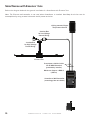
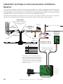
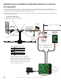
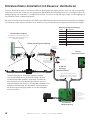
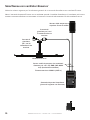
SmartSense with Essence
®
fans
Refer to the diagram below for the general installation of a SmartSense with Essence
®
fans.
Note: The Essence wall controller is not used when SmartSense is installed. Start/Stop for the fan can be
accomplished by using a switch inline with the AC power to the fan.
MODE
FAN SPEED
THRESHOLD TEMPERATURE
10%
55°F
100%
100°F
WINTER MODE
SUMMER MODE
MANUAL
Ceiling-mounted Upper
Temperature Sensor
Essence Fan
Junction Box
for Low Voltage
Control Wiring
Junction Box
for High Voltage
Power Wiring
SmartSense Wall Controller
(mounting plate not shown)
2-conductor shielded cable
18–22 AWG Stranded
(provided by installer)
Maximum distance >1000 ft
(>305 m)

WWW.BIGASSSOLUTIONS.COM © 2015 DELTA T CORP. ALL RIGHTS RESERVED.
11
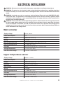
ELECTRICAL INSTALLATION
WARNING: Disconnect fan and controller from power supply before installing the SmartSense.
WARNING: To reduce the risk of electric shock, wiring should be performed by a qualified electrician!
Incorrect assembly can cause electric shock or damage the motor and the controller! Hazard of electrical
shock!
WARNING: Installation must be in accordance with the National Electrical Code, ANSI/NFPA 70-2011,
and all local codes. The procedures and techniques outlined in this manual are merely a guide for proper
installation. Code compliance is your responsibility! Failure to comply with these codes could result in
personal injury or property damage.
WARNING: The fan controllers contain high voltage capacitors which take time to discharge after removal
of mains supply. Before working on the fan controller, ensure isolation of mains supply from line inputs
at the fan controller’s disconnect (L1, L2/N, L3). Wait three minutes for capacitors to discharge to safe
voltage levels. Failure to do so may result in personal injury or death. Note: Darkened display LEDs are
not an indication of safe voltage levels.
Wall controller
Supply voltage
+24 VDC, 100 mA
Power consumption
≤ 1 W
Output
4–20 mA DC current loop
Wiring
18–22 AWG
Max wiring distance (ft)
((Vsupply-10 V)/0.02 A) / (Wire Ohms per Foot x 2)
Operating temperature
32° to 100° F (0° to 38° C)
Humidity
95% Relative humidity. Board is conformal coated
Storage temperature
14° to 122° F (-10° to 50° C)
ESD withstand voltage
+/- 4 kV Air, +/- 4 kV Contact
Upper temperature sensor
Supply voltage
+10 VDC to +24 VDC
Power consumption
≤ 1 W
Output
4–20 mA DC current loop
Accuracy
+/- 1° @ 77° F (+/- 0.5° @ 25° C)
Non-linearity
+/- 0.5° F
Wiring
18–22 AWG
Operating temperature
32° to 100° F (0° to 38° C)
Humidity
95% Relative humidity. Board is conformal coated.
Storage temperature
14° to 122° F (-10° to 50° C)
ESD withstand voltage
+/- 4 kV Air, +/- 4 kV Contact

WWW.BIGASSSOLUTIONS.COM © 2015 DELTA T CORP. ALL RIGHTS RESERVED.
12
RA RB RC
AVI
ACI
NPN
PNP
READY RUN FAULT
1 2 3
1 2 3
ON
ON
Analog Current Input “ACI” (+)Analog Common “ACM” (-)
Variable Frequency Drive
(cover removed)
Upper
Temperature
Sensor
SmartSense
Wall Controller
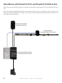
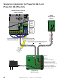
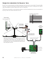
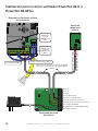
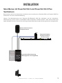
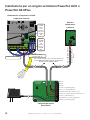
Single fan installation for Powerfoil X2.0 and
Powerfoil X2.0Plus fans
Reserved
Reserved
Reserved
2 conductor shielded cable 18-22 AWG Stranded (provided
by installer) Maximum distance >1000 ft (>305 m)
CAT5 Out
to PFX
wall pad
BLACK
RED
DC Common (shield) (Gray)
DC Common (shield) (BLACK)
DC Common (shield) (Gray)
4–20 mA Input from RTS (Black)
+24 VDC RTS Supply Out (Red)
4–20 mA Out to Fan Controller (Red)
4–20 mA Out (Black)
+24 VDC Supply In (GRAY/WHITE)
+24 VDC In (Red)
Verify that
AVI/ACI is
set to the
DOWN
position for
ACI mode.
Verify that
NPN/PNP
is set to
the UP
position for
NPN mode.
Top of Wall Pad

WWW.BIGASSSOLUTIONS.COM © 2015 DELTA T CORP. ALL RIGHTS RESERVED.
13
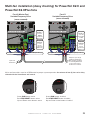
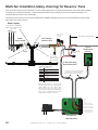
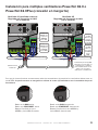
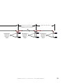
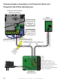
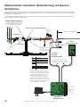
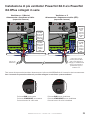
Multi-fan installation (daisy chaining) for Powerfoil X2.0 and
Powerfoil X2.0Plus fans
RA RB RC
AVI
ACI
NPN
PNP
READY RUN FAULT
1 2 3
1 2 3
ON
ON
RA RB RC
AVI
ACI
NPN
PNP
READY RUN FAULT
1 2 3
1 2 3
ON
ON
P FWD REV REM LOC
MODE
LOCAL
REM
RUN STOP FWD REV REM LOC
U
H
F
MODE
LOCAL
REM
RED
RED
BLACK BLACK
Verify that
AVI/ACI is
set to the
DOWN
position for
ACI mode.
Verify that
NPN/PNP
is set to
the UP
position for
NPN mode.
Verify that
AVI/ACI is
set to the
UP position
for AVI
mode.
Verify that
NPN/PNP
is set to
the UP
position for
NPN mode.
BLACK
RED
Analog Common “ACM” (-)
BLACK
RED
Analog Common “ACM” (-)
Output to up to two (2)
additional downstream
VFDs. Settings and wiring
for remaining VFDs shall
be the same as those
shown here for Fan #2.
Input from
SmartSense
Fan #1 (Master Fan)
Variable Frequency Drive
(cover removed)
Fan #2
Variable Frequency Drive
(cover removed)
Green RUN button active
Red STOP/RESET button active
Up and Down arrow buttons active
Green RUN button disabled
Red STOP/RESET button disabled
Up and Down arrow buttons disabled
All fan wall controllers must be in REM mode for proper system operation. A maximum of four (4) fan can be daisy
chained with the SmartSense wall control.
RA RB RC
AVI
ACI
NPN
PNP
READY RUN FAULT
1 2 3
1 2 3
ON
ON
RA RB RC
AVI
ACI
NPN
PNP
READY RUN FAULT
1 2 3
1 2 3
ON
ON
P FWD REV REM LOC
MODE
LOCAL
REM
RUN STOP FWD REV REM LOC
U
H
F
MODE
LOCAL
REM
RA RB RC
AVI
ACI
NPN
PNP
READY RUN FAULT
1 2 3
1 2 3
ON
ON
RA RB RC
AVI
ACI
NPN
PNP
READY RUN FAULT
1 2 3
1 2 3
ON
ON
P FWD REV REM LOC
MODE
LOCAL
REM
RUN STOP FWD REV REM LOC
U
H
F
MODE
LOCAL
REM
Analog Voltage Output “AFM” (+) Analog Voltage Output “AFM” (+)
Analog Current Input “ACI” (+)
Analog Voltage Input “AVI” (+)

WWW.BIGASSSOLUTIONS.COM © 2015 DELTA T CORP. ALL RIGHTS RESERVED.
14
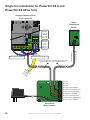
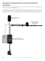
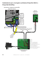
Single fan installation for Powerfoil X3.0 and
Powerfoil X3.0Plus fans
RA RB RC
AVI
ACI
NPN
PNP
READY RUN FAULT
1 2 3
1 2 3
ON
ON
Analog Current Input “ACI” (+)Analog Common “ACM” (-)
Variable Frequency Drive
(cover removed)
Upper
Temperature
Sensor
SmartSense
Wall Controller
Reserved
Reserved
Reserved
2 conductor shielded cable 18-22 AWG Stranded (provided
by installer) Maximum distance >1000 ft (>305 m)
CAT5 Out
to PFX
wall pad
BLACK
RED
DC Common (shield) (GRAY)
DC Common (shield) (BLACK)
DC Common (shield) (GRAY)
4–20 mA Input from RTS (BLACK)
+24 VDC RTS Supply Out (RED)
4–20 mA Out to VFD (RED)
4–20 mA Out (BLACK)
+24 VDC Supply In (GRAY/WHITE)
+24 VDC In (RED)
Verify that
AVI/ACI is
set to the
DOWN
position for
ACI mode.
Verify that
NPN/PNP
is set to
the UP
position for
NPN mode.
Top of Wall Pad

WWW.BIGASSSOLUTIONS.COM © 2015 DELTA T CORP. ALL RIGHTS RESERVED.
15
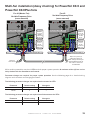
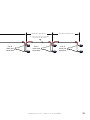
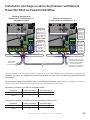
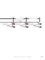
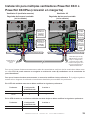
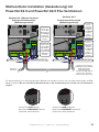
Multi-fan installation (daisy chaining) for Powerfoil X3.0 and
Powerfoil X3.0Plus fans
RA RB RC
AVI
ACI
NPN
PNP
READY RUN FAULT
1 2 3
1 2 3
ON
ON
RA RB RC
AVI
ACI
NPN
PNP
READY RUN FAULT
1 2 3
1 2 3
ON
ON
RED
RED
BLACK BLACK
Verify that
AVI/ACI is
set to the
DOWN
position for
ACI mode.
Verify that
NPN/PNP
is set to
the UP
position for
NPN mode.
Verify that
AVI/ACI is
set to the
UP position
for AVI
mode.
Verify that
NPN/PNP
is set to
the UP
position for
NPN mode.
BLACK
RED
Analog Common “ACM” (-)
BLACK
RED
Analog Common “ACM” (-)
Output to up to two (2)
additional downstream
VFDs. Settings and wiring for
remaining VFDs shall be the
same as those shown here
for Fan#2 VFD.
Input from
wall controller
Fan #1 (Master Fan)
Variable Frequency Drive
(cover removed)
Fan #2
Variable Frequency Drive
(cover removed)
All fan auxiliary controllers must be in REM mode for proper system operation. A maximum of four (4) fans can be
daisy chained with the SmartSense wall control.
Parameter changes are required for proper system operation. See the following page for a detailed wiring
diagram and instructions on changing parameters.
The following parameter changes are required on the master fan VFD:
Parameter Default setting Change to
02-00 3 2
02-01 3 1
The following parameter changes are required on all downstream fan VFDs:
Parameter Default setting Change to
02-00 3 1
02-01 3 1
Analog Voltage Output “AFM” (+) Analog Voltage Output “AFM” (+)
Analog Current Input “ACI” (+) Analog Voltage Input “AVI” (+)

WWW.BIGASSSOLUTIONS.COM © 2015 DELTA T CORP. ALL RIGHTS RESERVED.
16
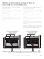
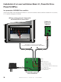
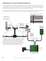
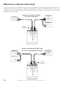
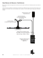
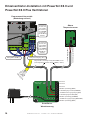
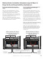
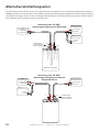
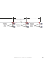
Single fan installation for Basic 6
®
, Powerfoil
®
8, and
Powerfoil
®
8Plus fans
U/T1 V/T2 W/T3
PE
L1 L2 L3
1 2 5 6 13A 13B 13C 14 30 16 1725 4 11
1 2 5 6 13A 13B 13C 14 30 16 1725 4 11
Basic 6
®
, Powerfoil
®
8, or Powerfoil
®
8Plus
VFD (cover removed)
RED
BLACK
Reserved
Reserved
Reserved
DC Common (Shield) (Gray)
DC Common (Shield) (Black)
DC Common (Shield) (Gray)
4–20 mA Input from RTS (Black)
+24 VDC RTS Supply Out (Red)
4–20 mA Out to Fan Controller (Red)
+24 VDC Supply In (Gray w/ White)
Top of Wall Pad
4–20 mA Out (Black)
+24 VDC In (Red)
Parameter Changes ARE required
P101 “Standard Reference Source” must be changed from “0” for keypad operation to “2” for 4-20mA analog input
operation.
2 conductor shielded cable 18-22AWG Stranded
(provided by installer) Maximum distance >1000ft
Upper
Temperature
Sensor
SmartSense
Wall Controller
La pagina si sta caricando...
La pagina si sta caricando...
La pagina si sta caricando...
La pagina si sta caricando...
La pagina si sta caricando...
La pagina si sta caricando...
La pagina si sta caricando...
La pagina si sta caricando...
La pagina si sta caricando...
La pagina si sta caricando...
La pagina si sta caricando...
La pagina si sta caricando...
La pagina si sta caricando...
La pagina si sta caricando...
La pagina si sta caricando...
La pagina si sta caricando...
La pagina si sta caricando...
La pagina si sta caricando...
La pagina si sta caricando...
La pagina si sta caricando...
La pagina si sta caricando...
La pagina si sta caricando...
La pagina si sta caricando...
La pagina si sta caricando...
La pagina si sta caricando...
La pagina si sta caricando...
La pagina si sta caricando...
La pagina si sta caricando...
La pagina si sta caricando...
La pagina si sta caricando...
La pagina si sta caricando...
La pagina si sta caricando...
La pagina si sta caricando...
La pagina si sta caricando...
La pagina si sta caricando...
La pagina si sta caricando...
La pagina si sta caricando...
La pagina si sta caricando...
La pagina si sta caricando...
La pagina si sta caricando...
La pagina si sta caricando...
La pagina si sta caricando...
La pagina si sta caricando...
La pagina si sta caricando...
La pagina si sta caricando...
La pagina si sta caricando...
La pagina si sta caricando...
La pagina si sta caricando...
La pagina si sta caricando...
La pagina si sta caricando...
La pagina si sta caricando...
La pagina si sta caricando...
La pagina si sta caricando...
La pagina si sta caricando...
La pagina si sta caricando...
La pagina si sta caricando...
La pagina si sta caricando...
La pagina si sta caricando...
La pagina si sta caricando...
La pagina si sta caricando...
La pagina si sta caricando...
La pagina si sta caricando...
La pagina si sta caricando...
La pagina si sta caricando...
La pagina si sta caricando...
La pagina si sta caricando...
La pagina si sta caricando...
La pagina si sta caricando...
La pagina si sta caricando...
La pagina si sta caricando...
La pagina si sta caricando...
La pagina si sta caricando...
La pagina si sta caricando...
La pagina si sta caricando...
La pagina si sta caricando...
La pagina si sta caricando...
La pagina si sta caricando...
La pagina si sta caricando...
La pagina si sta caricando...
La pagina si sta caricando...
La pagina si sta caricando...
La pagina si sta caricando...
La pagina si sta caricando...
La pagina si sta caricando...
La pagina si sta caricando...
La pagina si sta caricando...
La pagina si sta caricando...
La pagina si sta caricando...
La pagina si sta caricando...
La pagina si sta caricando...
La pagina si sta caricando...
La pagina si sta caricando...
La pagina si sta caricando...
La pagina si sta caricando...
La pagina si sta caricando...
La pagina si sta caricando...
La pagina si sta caricando...
La pagina si sta caricando...
La pagina si sta caricando...
La pagina si sta caricando...
La pagina si sta caricando...
La pagina si sta caricando...
La pagina si sta caricando...
La pagina si sta caricando...
La pagina si sta caricando...
La pagina si sta caricando...
La pagina si sta caricando...
La pagina si sta caricando...
La pagina si sta caricando...
La pagina si sta caricando...
La pagina si sta caricando...
La pagina si sta caricando...
La pagina si sta caricando...
La pagina si sta caricando...
La pagina si sta caricando...
La pagina si sta caricando...
La pagina si sta caricando...
La pagina si sta caricando...
La pagina si sta caricando...
La pagina si sta caricando...
La pagina si sta caricando...
La pagina si sta caricando...
La pagina si sta caricando...
La pagina si sta caricando...
La pagina si sta caricando...
La pagina si sta caricando...
La pagina si sta caricando...
La pagina si sta caricando...
La pagina si sta caricando...
La pagina si sta caricando...
La pagina si sta caricando...
La pagina si sta caricando...
-
 1
1
-
 2
2
-
 3
3
-
 4
4
-
 5
5
-
 6
6
-
 7
7
-
 8
8
-
 9
9
-
 10
10
-
 11
11
-
 12
12
-
 13
13
-
 14
14
-
 15
15
-
 16
16
-
 17
17
-
 18
18
-
 19
19
-
 20
20
-
 21
21
-
 22
22
-
 23
23
-
 24
24
-
 25
25
-
 26
26
-
 27
27
-
 28
28
-
 29
29
-
 30
30
-
 31
31
-
 32
32
-
 33
33
-
 34
34
-
 35
35
-
 36
36
-
 37
37
-
 38
38
-
 39
39
-
 40
40
-
 41
41
-
 42
42
-
 43
43
-
 44
44
-
 45
45
-
 46
46
-
 47
47
-
 48
48
-
 49
49
-
 50
50
-
 51
51
-
 52
52
-
 53
53
-
 54
54
-
 55
55
-
 56
56
-
 57
57
-
 58
58
-
 59
59
-
 60
60
-
 61
61
-
 62
62
-
 63
63
-
 64
64
-
 65
65
-
 66
66
-
 67
67
-
 68
68
-
 69
69
-
 70
70
-
 71
71
-
 72
72
-
 73
73
-
 74
74
-
 75
75
-
 76
76
-
 77
77
-
 78
78
-
 79
79
-
 80
80
-
 81
81
-
 82
82
-
 83
83
-
 84
84
-
 85
85
-
 86
86
-
 87
87
-
 88
88
-
 89
89
-
 90
90
-
 91
91
-
 92
92
-
 93
93
-
 94
94
-
 95
95
-
 96
96
-
 97
97
-
 98
98
-
 99
99
-
 100
100
-
 101
101
-
 102
102
-
 103
103
-
 104
104
-
 105
105
-
 106
106
-
 107
107
-
 108
108
-
 109
109
-
 110
110
-
 111
111
-
 112
112
-
 113
113
-
 114
114
-
 115
115
-
 116
116
-
 117
117
-
 118
118
-
 119
119
-
 120
120
-
 121
121
-
 122
122
-
 123
123
-
 124
124
-
 125
125
-
 126
126
-
 127
127
-
 128
128
-
 129
129
-
 130
130
-
 131
131
-
 132
132
-
 133
133
-
 134
134
-
 135
135
-
 136
136
-
 137
137
-
 138
138
-
 139
139
-
 140
140
-
 141
141
-
 142
142
-
 143
143
-
 144
144
-
 145
145
-
 146
146
-
 147
147
-
 148
148
-
 149
149
-
 150
150
-
 151
151
-
 152
152


Big Ass Fans Powerfoil X3.0 Plus Guida d'installazione
- Tipo
- Guida d'installazione
in altre lingue
Altri documenti
-
Delta 72045T-AR Informazioni sul prodotto
-
Tecnosystemi Regulator Manuale del proprietario
-
 Sirocco LedsC4 Guida d'installazione
-
Dimplex VVTP75 Manuale utente
-
-
Robertshaw SMART 3000 Touchscreen Thermostat Guida d'installazione
-
WEG SSW06 Guida utente
-
Intel SRKA4 - Server Platform - 0 MB RAM Manuale utente
-
bora ULIE20 Assembly Instruction
