
DWB01/02/03CMxx10A-PWB01/02/03CMxx10A/R0/instr/MF/08.02.05 code 8020680 http://www.carlogavazzi.com/ CARLO GAVAZZI
DWB01CMxx10A
P
WB01CMxx10A
DWB02CMxx10A
P
WB02CMxx10A
D
WB03CMxx10A
PWB03CMxx10A
3
-Phase load guard relay
3
-Phasen Lastüberwachungsrelais
Relais de reprise de charge triphasé
Relé de control de carga par sistemas trifásicos
Relè trifase per il monitoraggio del carico
3-faset belastningsvagt
Installation instructions
Installationshinweise
Notice d’installation
Instrucciones de instalación
Istruzioni per l’installazione
Installationsvejledning
Mounting and installation by skilled people only!
Montage und Installation nur durch Fachpersonal!
Montage et installation par des personnes habilitées seulement!
El montaje e instalación ha de realizarlo solo personal con experiencia!
Il montaggio e l’installazione va eseguito da parte di personale addestrato!
Montering og installation må kun foretages af faguddannede personer!
ENGLISH DEUTSCH FRANÇAIS
ESPAÑOL
I
TALIANO
D
ANSK
1 Connections (DWB01/02/03)
3-Phase voltage:
Connect
the 3-Phase power supply
to the terminals L1, L2 and
L3 taking care of the
sequence.
1-Phase voltage
(DWB0XCM2310A only):
Connect the 1-Phase power
supply to the terminals L1
and L2 and wire a cable
between terminals L2 and
L3.
Current, direct: Connect
the current of the phase L1
(or L if 1-Phase) to the ter-
minals I1 and I2.
Current, standard CT:
Connect the output current
from the standard CT to the
terminals I1 and I2.
Current, MI CT: Connect
the grey cable from the MI
CT to the terminal U1 and
the black cable to the termi-
nal U2.
Connect the relay output
according to the ratings.
Automatic screwdriver can
be used (max torque 0.5
Nm)
Keep power OFF while
connecting!
2 Connections (PWB01/02/03)
3-Phase voltage:
Connect
the 3-Phase power supply
to the ter
minals 5, 6 and 7
taking care of the sequence.
1-Phase voltage
(PWB0XCM2310A only):
Connect the 1-Phase power
supply to the terminals 5
and 6 and wire a cable
between terminals 6 and 7.
Cur
r
ent, direct:
Connect
the current of the phase L1
(or L if 1-Phase) to the ter-
minals 11 and 10.
Current, standard CT:
Connect the output current
from the standard CT to the
terminals 11 and 10.
Current, MI CT: Connect
the gr
ey cable fr
om the MI
CT to the ter
minal 9 and the
black cable to the terminal
8.
Connect the relay output
according to the ratings.
Keep power OFF while
connecting!
3 Setting of function and
input range
Select the desired function
setting the DIP-switches 1
to 4 as shown on the left
column.
To access the DIP switches
open the grey plastic cover
as shown on the left.
SW1 selects the input cur
-
r
ent range: 10 A or 5A.
For using the MI CT the 5A
range must be selected
(SW1 OFF).
If the input current is
below 10% of the full scale
value the relay is conven-
tionally in alar
m condition.
1 Anschlüsse (DWB01/02/03)
3-Phasenspannung:
Schließen Sie die
Betriebsspannung an die
Klemmen L1, L2 und L3 an;
achten Sie dabei auf die
Phasenfolge.
1
-Phasenspannung (nur
DWB0XCM2310A):
Schließen Sie die
Betriebsspannung an die
Klemmen L1 und L2 an;
überbrücken Sie die
Klemmen L2 und L3.
Strom, direkt: Schließen
Sie die stromführenden
Leiter der Phase L1 (oder L
im 1-Phasennetz) an die
Klemmen I1 und I2 an.
Strom, Standardwandler:
Schließen Sie die
Sekundärstromleitungen an
die Klemmen I1 und I2 an.
Strom, Wandler Typ MI:
Schließen Sie die graue
Leitung des Wandler an
Klemme U1 und die schwar-
ze Leitung an Klemme U2 an.
Schließen Sie den
Relaisausgang entspre-
chend den Betriebsdaten
an. Verwenden Sie dazu
einen automatischen
Schraubendreher (Max.
Drehmoment 0,5 Nm).
Achten Sie beim
Anschluß auf
Spannungsfreiheit!
2 Anschlüsse (PWB01/02/03)
3-Phasenspannung:
Schließen Sie die
Betriebsspannung an die
K
lemmen 5, 6 und 7 an;
achten Sie dabei auf die
Phasenfolge.
1-Phasenspannung (nur
PWB0XCM2310A):
Schließen Sie die
Betriebsspannung an die
Klemmen 5 und 6 an; über-
brücken Sie die Klemmen 6
und 7.
Str
om, dir
ekt:
Schließen
Sie die stromführenden
Leiter der Phase L1 (oder L
im 1-Phasennetz) an die
Klemmen 11 und 10 an.
Strom, Standardwandler:
Schließen Sie die
Sekundärstromleitungen an
die Klemmen 11 und 10 an.
Str
om, W
andler T
yp MI:
Schließen Sie die graue
Leitung des W
andler an
Klemme 9 und die schwarze
Leitung an Klemme 8 an.
Schließen Sie den
Relaisausgang entspre-
chend den Betriebsdaten an.
Achten Sie beim
Anschluß auf
Spannungsfreiheit!
3 Einstellung von Funktion
und Eingangsbereich
Wählen Sie die gewünschte
Funktion mit den DIP-
Schaltern 1 bis 4, wie im lin-
ken Bild gezeigt. Öffnen Sie
die graue
Kunststoffabdeckung wie
im linken Bild gezeigt, um
die DIP-Schalter einstellen
zu können.
SW1: Eingangsstr
om-
Ber
eich einstellen: 10 A
oder 5 A.
Wählen Sie bei
Verwendung des Wandlers
MI den Bereich 5 A (SW1 in
Stellung AUS).
Bei einem Eingangsstr
om
kleiner als 1/10 des
Ber
eichsendwer
tes wir
d
eine Alar
mmeldung gege
-
ben.
1 Raccordements
(DWB01/02/03)
Tension triphasée:
Raccorder l'alimentation tri-
phasée aux bornes L1, L2 ,
L3, en respectant la séquen-
ce indiquée.
1-Tension monophasée
(DWB0XCM2310A seule-
ment): Raccorder l'alimen-
tation monophasée aux bor-
nes L1 et L2 et câbler les
bornes L2 et L3 entre elles
Courant Continu:
Raccorder le courant de la
phase L1 (ou L si monopha-
sé) aux bornes I1 et I2.
Transformateur Standard:
Raccorder la sortie courant
transformateur standard aux
bornes I1 et I2.
Transformateur de
courant type MI: Raccorder
le câble gris du transforma-
teur MT à la borne U1 et le
câble noir à la borne U2.
Raccorder le relais de sortie
selon les caractéristiques.
L'utilisation d'une visseuse
électrique est autorisé (ser-
rage max 0,5 Nm).
Attention Danger: effec-
tuer tous les raccorde-
ments Hors Tension!
2 Raccordements
(PWB01/02/03)
Tension triphasée:
Raccorder l'alimentation tri-
phasée aux bornes 5,6 et 7
en respectant la séquence
indiquée.
Tension monophasée
(PWB0XCM2310A seule-
ment): Raccor
der l'alimen
-
tation monophasée aux bor-
nes 5 et 6 et câbler les bor
-
nes 6 et 7 entre elles.
Courant Continu:
Raccorder le courant de la
phase L1 (ou L si monopha-
sé) aux bor
nes 11 et 10.
Transformateur Standard:
Raccor
der la sortie courant
transformateur standard aux
bor
nes 11 et 10.
Transformateur de
courant type MI: Raccorder
le câble gris du transforma-
teur MT à la borne 9 et le
câble noir à la borne 8.
Raccorder le relais de sortie
en fonction des caractéristi-
ques.
Attention Danger: ef
fec
-
tuer tous les raccorde-
ments Hors Tension!
3 Paramétrage de la fonc-
tion et réglage de la
gamme d'entrée
Sélectionner la fonction
souhaitée à l'aide des DIP
switch 1 à 4 , comme illustré
à gauche.
Pour accéder aux DIP
switch, ouvrir le capot en
matièr
e plastique grise,
comme illustré à gauche.
SW1 sélectionne la gamme
du courant d'entrée: 10 A ou
5A.
Pour utiliser le TC MI, la
fréquence 5A doit êtr
e
sélectionnée (SW1 OFF).
Si le courant d'entrée est
inférieur à 10 % de la
valeur en échelle totale, le
relais est par défaut en
mode alarme.
1 Conexiones (DWB01/02/03)
Trifásica:
Conectar la ali-
mentación trifásica a los ter-
minales L1, L2 y L3, tenien-
do en cuenta la secuencia.
Monofásica (solo para
DWB0XCM2310A):
Conectar la alimentación
monofásica a los terminales
L1 y L2 y cablear los termi-
nales L2 y L3.
Intensidad, directa:
Conectar la intensidad de la
fase L1 (o L si es monofási-
ca) a los terminales I1 e I2.
Intensidad, trafo estándar:
Conectar la salida de la
intensidad del trafo están
-
dar a los terminales I1 e I2.
Intensidad, trafo MI:
Conectar el cable gris del
trafo MI al terminal U1 y el
cable negro al terminal U2.
Conectar la salida de relé
según las escalas. Se puede
usar un destornillador auto-
mático (máx. par de apriete
0,5 Nm).
El equipo debe estar
desconectado mientras
se realizan las conexio-
nes!
2 Conexiones (PWB01/02/03)
Trifásica:
Conectar la ali-
mentación trifásica a los ter
-
minales 5, 6 y 7, teniendo en
cuenta la secuencia.
Monofásica (solo para
PWB0XCM2310A):
Conectar la alimentación
monofásica a los ter
minales
5 y 6 y cablear los termina-
les 6 y 7.
Intensidad, directa:
Conectar la intensidad de la
fase L1 (o L si es monofási-
ca) a los terminales 11 y 10.
Intensidad, trafo estándar:
Conectar la salida de inten-
sidad del trafo estándar a
los terminales 11 y 10.
Intensidad, trafo MI:
Conectar el cable gris del
trafo MI al ter
minal 9 y el
cable negr
o al ter
minal 8.
Conectar la salida de relé
según las escalas.
El equipo debe estar
desconectado mientras
se r
ealizan las conexio
-
nes!
3 Ajuste de funciones y
rango de entrada
Seleccionar la función que
se desee con los interrupto-
r
es DIP 1 al 4, como se indi
-
ca a la izquierda. Para acce-
der a los interruptores DIP,
despr
ender la tapa de plá-
stico gris como se indica.
SW1 selecciona la escala de
intensidad de la entrada: 10
ó 5 A.
Al utilizar el trafo MI hay
que seleccionar la escala
de 5 A (SW1 OFF).
Si la entrada de intensidad
está por debajo del 10%
del valor de la escala com
-
pleta, el relé está conven-
cionalmente en condición
de alar
ma.
1 Collegamenti (DWB01/02/03)
Tensione trifase:
Collegare
la tensione trifase di alimen-
tazione ai morsetti L1, L2 ed
L3 rispettando la sequenza.
Tensione monofase
(
solo DWB0XCM2310A):
Collegare la tensione mono-
fase di alimentazione ai
m
orsetti L1 ed L2 e cortocir-
cuitare i morsetti L2 ed L3.
Corrente, inserzione diret-
ta: Collegare la corrente
della fase L1 (o L se si usa
un carico monofase) ai mor-
setti I1 ed I2.
Corrente, TA standard:
Collegare l’uscita del TA
standard ai morsetti I1 ed I2.
Corrente, TA tipo MI:
Collegar
e il cavo grigio del
MI al morsetto U1 e il cavo
nero al morsetto U2
Collegare l'uscita relè
secondo i valori di carico
indicati. La coppia massima
in caso di uso di avvitatori
automatici è 0,5 Nm.
Staccar
e l'alimentazio-
ne prima di collegare lo
strumento!
2 Collegamenti (PWB01/02/03)
T
ensione trifase:
Collegar
e
la tensione trifase di alimen-
tazione ai morsetti 5, 6 e 7
rispettando la sequenza.
Tensione monofase
(solo PWB0XCM2310A):
Collegare la tensione mono-
fase di alimentazione ai
morsetti 5 e 6 e cortocircui-
tare i morsetti 6 e 7.
Corrente, inserzione diret-
ta: Collegar
e la cor
r
ente
della fase L1 (o L se si usa
un carico monofase) ai mor-
setti 11 e 10.
Corrente, TA standard:
Collegare l’uscita del TA
standard ai morsetti 11 e 10.
Corrente, TA tipo MI:
Collegare il cavo grigio del
MI al morsetto 9 e il cavo
ner
o al morsetto 8.
Collegare l'uscita relè
secondo i valori di carico
indicati.
Staccar
e l'alimentazio
-
ne prima di collegare lo
str
umento!
3 Messa a punto della por-
tata d'ingr
esso e della fun
-
zione.
Impostare la funzione desi-
derata agendo sui DIP
switch da 1 a 4 come indi-
cato nella colonna di sini-
stra. Per acceder
e ai DIP
switch aprir
e lo spor
tellino
grigio usando un cacciavite
come mostrato in figura.
SW1 seleziona la gamma
della corrente di ingresso:
10 A oppur
e 5 A.
Per usare un TA di tipo MI
deve essere selezionata la
gamma 5 A (SW1 OFF). Se
la cor
r
ente di ingresso è
sotto il 10% rispetto al
fondo scala impostato il
r
elè è per convenzione in
stato di allarme.
1 Tilslutninger (DWB01/02/03)
3-faset spænding:
Slut den
3-fasede forsyningsspæn-
ding til klemme L1, L2 og
L3. Rækkefølgen er meget
vigtig.
1-faset spænding
(kun DWB0XCM2310A):
Slut den 1-fasede forsy-
ningsspænding til klemme
L1 og L2, og forbind klem-
me L2 og L3 med et kabel.
Strøm, direkte: Slut strøm-
men i fase L1 (eller L ved 1-
faset) til klemme I1 og I2.
Strøm, standard-strøm-
måletransformator: Slut
udgangsstrømmen fra stan-
dard-strømmåletransforma-
toren til klemme I1 og I2.
Strøm, MI-strømmåletran-
sformator: Slut det grå
kabel fra MI-strømmåletran-
sformatoren til klemme U1,
og slut det sor
te kabel til
klemme U2.
Tilslut den relæstyrede
udgang i forhold til belast-
ningen. Anvend evt. en
automatisk skruetrækker
(maks. tilspændingsmoment
0,5 Nm).
Strømmen skal være
SLUKKET under tilslut-
ningen!
2 Tilslutninger (PWB01/02/03)
3-faset spænding:
Slut den
3-fasede forsyningsspæn-
ding til klemme 5, 6, og 7.
Rækkefølgen er meget vigtig.
1-faset spænding
(kun PWB0XCM2310A):
Slut den 1-fasede forsy-
ningsspænding til klemme 5
og 6, og forbind klemme 6
og 7 med et kabel.
Strøm, direkte: Slut strøm-
men i fase L1 (eller L ved 1-
faset) til klemme 11 og 10.
Strøm, standar
d-strøm
-
måletransfor
mator:
Slut
udgangsstrømmen fra stan-
dar
d-strømmåletransfor
ma
-
toren til klemme 11 og 10.
Strøm, MI-strømmåletran-
sformator:
Slut det grå
kabel fra MI-strømmåletran-
sformatoren til klemme 9, og
slut det sor
te kabel til klem-
me 8.
Tilslut den relæstyrede
udgang i for
hold til belast
-
ningen.
Strømmen skal være
SLUKKET under tilslut-
ningen!
3 Indstilling af funktions- og
indgangsområde
Vælg den ønskede funktion
ved at indstille DIP-switch 1
og 4 som vist i venstr
e
kolonne.
Adgang til DIP-switches
opnås ved at åbne det grå
plastdæksel som vist til ven-
stre.
Med SW1 vælges indgangs-
strømområdet: 10 A eller
5A.
Hvis MI-strømmåletran
-
sformatoren skal anven-
des, skal 5A-området væl
-
ges (SW1 deaktiveret).
Hvis indgangsstrømmen
er under 10% af fuldskala
-
værdien, står relæet nor-
malt i alarmtilstand.
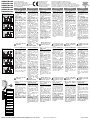
DWB01/02/03 - 3-Phase voltage,
standard CT
DWB01/02/03 - 3-Phase voltage, MI CT
DWB0XCM2310A - 1-Phase voltage,
direct connection
PWB01/02/03 - 3-Phase voltage,
standard CT
PWB01/02/03 - 3-Phase voltage, MI CT
PWB0XCM2310A - 1-Phase voltage,
direct connection
Input Range
ON:
10 A
OFF: 5 A / MI CT
Relay
ON: N.D.
OFF: N.E.
Contact input
(SW3 OFF)
ON:
Latch
OFF:
Inhibit
Contact input mode
ON: Start/Stop
OFF: Latch/Inhibit
Measuring voltage V
AC
(DWB02/03-
PWB02/03 only)
SW5 ON ON OFF OFF
SW6 ON OFF ON OFF
M23 208 220 230 240
M48 380 400 415 480
M69 600 690 600 690

DWB01/02/03CMxx10A-PWB01/02/03CMxx10A/R0/instr/MF/08.02.05 code 8020680 http://www.carlogavazzi.com/ CARLO GAVAZZI
ENGLISH DEUTSCH FRANÇAIS
ESPAÑOL
ITALIANO DANSK
4 Setting of function and
input range
SW2 selects the relay work-
ing mode: normally de-ener-
gized (relay energized in
alarm condition) or normally
energized (relay de-ener-
gized in alarm condition).
SW3 selects the contact
input working mode:
Start/Stop or Latch/Inhibit
function.
SW4 selects the contact
input function: latch or
inhibit of alarm enable.
SW4
does not affect the work-
ing mode if SW3 is ON.
Do not open the DIP
switches cover if the
power supply is ON!
5 Contact input
Latch function (SW3 OFF,
SW4 ON):
The relay latches
in the alarm condition if
ther
e is no connection
between the terminals Z1
and U1 (DWB01/02/03) or 2
and 9 (PWB01/02/03).
Inhibit function (SW3 OFF,
SW4 OFF):
To inhibit the
a
larm status short circuit the
terminals Z1 and U1
(DWB01/02/03) or 2 and 9
(PWB01/02/03).
Start/stop function (SW3
ON):
The device is active
when the terminals Z1 and
U1 (DWB01/02/03) or 2 and
9 (PWB01/02/03) are con-
nected.
6 Mechanical mounting
(DWB01/02/03)
Hang the device to the DIN-
rail being sure that the
spring closes. Use a screw-
driver to r
emove the pr
oduct
as shown in figure.
7 Startup and adjustment
Check if the cur
r
ent input
range is correct. Turn the
power supply ON.
The gr
een LED is ON.
Adjust the upper and lower
levels on the absolute scale
setting the left and right
centre knobs respectively.
Adjust the alarm and power
ON delay setting the right
and left lower knob.
See datasheet for the work-
ing mode explanation.
8 Note
The packing material should
be kept for redelivery in
case of replacement or
repair.
9 Terminals
3-Phase power supply
1-Phase power supply
(short circuit L2, L3 or 6, 7)
Current input (Direct or
standar
d CT)
Current input (MI CT)
Latch/Inhibit (SW3 OFF) or
Start/Stop (SW3 ON) contact
Relay output
Each terminal can accept up
to 2 x 2.5 mm
2
wir
es
(DWB01/02/03).
4 Paramétrage de la fonc-
tion et réglage de la
gamme d'entrée
SW2 sélectionne le mode
de fonctionnement du
relais: normalement désac-
tivé (relais actif en condi-
tion d'alarme) ou normale-
m
ent désactivé (relais
inactif en condition d'alar-
me). SW3 sélectionne le
mode de fonctionnement
des contacts d'entrée:
Marche/Arrêt ou fonction
mémorisation/interdiction.
SW4 sélectionne la fonction
des contacts d'entrée:
mémorisation/interdiction
de l'activation de l'alarme.
SW4 n'affecte pas le mode
de fonctionnement si SW3
est ON.
Ne pas ouvrir le capot
des DIP switch lorsque
l'alimentation est active.
5 Entrée contact
Fonction mémoire (SW3
OFF, SW4 ON):
Le relais
mémorise en position d'a-
larme s'il n'y a pas de con-
nexion entre les bornes Z1
et U1 (DWB01/02/03) et 2 et
9 (PWB01/02/03).
Fonction interdiction (SW3
OFF, SW4 OFF): Pour inter-
dire le fonctionnement de
l'alarme, court circuiter les
bornes Z1 et U1
(DWB01/02/03) et 2 et 9
(PWB01/02/03).
Fonction démarrage/arrêt
(SW3 ON):
l'appareil est
actif quand les bornes Z1 et
U1 (DWB01/02/03) ou 2 et 9
(PWB01/02/03) sont raccor-
dées.
6 Montage mécanique
(DWB01/02/03)
Accrocher l'appareil au rail
DIN et s'assurer que le res-
sort se referme bien. Pour
déposer l'appareil, utiliser
un tour
nevis comme illustré
sur la figure.
7 Démarrage et réglage
Vérifier que la gamme du
courant d'entrée est correc-
te. Mettre l'alimentation
sous tension.
La LED verte s'allume.
Régler les niveaux supérieur
et inférieur sur l’échelle, en
agissant respectivement sur
les boutons gauche et dr
oit.
Régler l'alarme et le temps
de mise sous tension en
agissant respectivement sur
les boutons gauche et droit.
Se référer à la fiche techni-
que pour l'explication sur le
mode de fonctionnement.
8 Nota
Conserver les matériaux de
conditionnement pour une
éventuelle réexpédition en
cas de remplacement ou de
réparation
9 Bornes
Alimentation triphasée
Alimentation monophasée
(court circuit L2, L3 or 6, 7)
Courant d'entrée (Continu
ou TC standard)
Courant d'entrée (TC MT)
Contact de mémorisation/
inter
diction (SW3 désactivé)
ou démarrage/arrêt (SW3
activé) r
elais de sor
tie activé
Relais de sortie
Chaque borne accepte jus-
qu'à deux conducteurs de
2,5 mm
2
(DWB01/02/03).
4 Ajuste de funciones y
rango de entrada
SW2 selecciona el modo de
trabajo del relé: normalmen-
te desactivado (relé ON en
condición de alarma) o nor-
malmente activado (relé
OFF en condición de alar-
ma).
SW3 selecciona la entrada
de contacto del modo de
trabajo : Arranque/Parada o
función de Enclavar/Inhibir
SW4 selecciona la función
de contacto de la entrada:
alarma enclavada o inhibi-
da.
SW4 no afecta al modo
de trabajo si SW3 está en
ON.
No abra la cubierta de
los interruptores DIP si
está conectada la ali-
mentación!
5 Entrada de contacto
Función de enclavamiento
(SW3·OFF, SW4 ON):
El relé
se enclava en condición de
alarma, si no hay conexión
entre los terminales Z1 y U1
(DWB1/02/03) ó entre 2 y 9
(PWB01/02/03).
Función de inhibición (SW3
OFF, SW4 OFF): Para inhibir
el estado de alarma, corto-
circuitar los terminales Z1 y
U1 (DWB01/02/03) o 2 y 9
(PWB01/02/03).
Función de arranque/para-
da (SW3 ON): El equipo está
activado cuando están
conectados los terminales
Z1 y U1 (DWB1/02/03) o 2 y
9 (PWB01/02/03).
6 Montaje mecánico
(DWB01/02/03)
Colocar el equipo en el car-
ril DIN, asegurándose que el
muelle cierra. Utilizar un
destornillador para
desprender el equipo como
se indica.
7 Puesta en marcha y ajuste
Compr
obar que la escala de
entrada de intensidad es
correcta. Conectar el equi-
po.
El LED ver
de se ilumina.
Ajustar los niveles superior
e inferior sobra la escala
con los potenciómetros
superiores izquierdo y dere-
cho r
espectivamente.
Ajustar la alarma y el retardo
de la alimentación con los
potenciómetros inferiores
derecho e izquierdo.
Véase su hoja de datos para
la explicación del modo de
operación
8 Nota
Conser
var el embalaje en
caso de devolver el equipo
para su cambio o r
epara
-
ción.
9 Terminales
Alimentación trifásica
Alimentación monofásica
(cortocircuitar L2, L3 o 6 y 7)
Entrada de intensidad (direc-
ta o con trafo estándar)
Entrada de intensidad (trafo
de intensidad MI)
Salida de r
elé de contacto:
Enclavar/Inhibir (SW3 OFF) o
Ar
ranque/Parada (SW3 ON)
Salida de relé
Cada terminal acepta
cables de hasta 2 x 2,5 mm
2
(DWB01/02/03).
4 Messa a punto della por-
tata d'ingresso e della fun-
zione.
SW2 seleziona il modo di
funzionamento del relè: nor-
malmente eccitato (relè dis-
eccitato in stato di allarme)
o normalmente diseccitato
(
relè eccitato in stato di
allarme).
SW3 seleziona il modo di
funzionamento dell’ingresso
di contatto: Start/Stop
oppure
Bloccaggio/Inibizione.
SW4 seleziona la funzione
dell’ingresso di contatto:
bloccaggio o inibizione del
funzionamento del relè.
SW4 non influenza il fun-
zionamento se SW3 è ON.
Non aprire lo sportello
DIP-switch se l'alimen-
tazione è collegata!
5 Ingresso di contatto
Funzione di Latch (SW3
OFF, SW4 ON):
Il relè rima-
ne bloccato in posizione di
allarme se non c’è collega-
mento fra i morsetti Z1 e U1
(DWB01/02/03) oppure 2 e 9
(PWB01/02/03).
Funzione di Inibizione
(SW3 OFF, SW4 ON): Per
inibire lo stato di allarme
collegare i morsetti Z1 e U1
(DWB01/02/03) oppure 2 e 9
(PWB01/02/03).
Funzione Start/stop (SW3
ON): Lo strumento è attivo
quando i morsetti Z1 e U1
(DWB01/02/03) oppure 2 e 9
(PWB01/02/03).
6 Montaggio sulla guida DIN
(DWB01/02/03)
Agganciare lo strumento alla
guida DIN verificando la
chiusura della molla. Per
rimuovere il prodotto dalla
guida usar
e un cacciavite
come mostrato in figura.
7 Accensione e regolazione
Controllare che la gamma
della corrente di ingresso
sia corretta. Alimentare lo
strumento. Il LED verde si
accende.
Impostar
e le soglie minima e
massima sulla scala agen-
do sulle manopole centrali
di sinistra e destra rispetti
-
vamente.
Impostar
e il ritar
do all’inser
-
zione e all’avvio agendo
sulle manopole in basso di
destra e sinistra rispettiva-
mente.
Vedere datasheet per il
modo di funzionamanto
8 Nota
Conservare l'imballo origi-
nale in caso di sostituzione
o riparazione.
9 Terminali di collegamento
Alimentazione trifase
Alimentazione monofase
(collegare L2 e L3 o 6 e 7)
Ingr
esso in corrente (Inserz.
diretta o TA standard)
Ingr
esso in cor
r
ente (TA tipo
MI)
Ingresso di Latch/Inibiz.
(SW3 OFF) o Star
t/Stop
(SW3 ON)
Uscita relè
Ad ogni morsetto possono
essere collegati 2 fili di
2,5 mm
2
(DWB01/02/03).
4 Indstilling af funktions- og
indgangsområde
Med SW2 vælges relæfunk-
tionen: normalt deaktiveret
(relæ aktiveret i alarmtil-
stand) eller normalt aktiveret
(relæ deaktiveret i alarmtil-
stand).
Med SW3 vælges kontak-
tindgangsdriftsfunktionen:
Start/stop- eller
selvholde/spærrefunktion.
Med SW4 vælges kontak-
tindgangsfunktionen: akti-
vering af selvholdefunktion
eller alarmspærring.
SW4
påvirker ikke driftsfunktio-
nen, hvis SW3 er aktiveret.
Dækslet til DIP-switche-
n
e må ikke åbnes, hvis
strømmen er tilsluttet!
5 Kontaktindgang
Selvholdefunktion (SW3
deaktiveret, SW4 aktive-
ret):
Relæet selvholder i
alar
mtilstanden, hvis der
ikke er forbindelse mellem
klemme Z1 og U1
(DWB01/02/03) eller 2 og 9
(PWB01/02/03).
Spærrefunktion (SW3
deaktiveret, SW4 deaktive-
ret): For at spærre alarmtil-
standen skal klemme Z1 og
U1 (DWB01/02/03) eller 2 og
9 (PWB01/02/03) kortsluttes.
Start/stop-funktion (SW3
aktiveret): Enheden er aktiv,
når klemme Z1 og U1
(DWB01/02/03) eller 2 og 9
(PWB01/02/03) er tilsluttet.
6 Mekanisk montering
(DWB01/02/03)
Når enheden monteres på
DIN-skinnen, skal det sikres,
at fjederen lukker. Brug en
skruetrækker til at fjerne
pr
oduktet som vist på illu
-
strationen.
7 Opstart og justering
Kontrollér, at indgangsstrø-
mområdet er korrekt. Tænd
for strømforsyningen.
Den grønne lysdiode er
TÆNDT.
Indstil vær
dier
ne for øvre og
nedre nivau på skalæn ved
at indstille midterste knap i
henholdsvis venstr
e og
højre side.
Juster alar
m- og indkobling
-
sforsinkelsen ved at indstille
nederste knap i højre og
venstre side.
Se datablad for beskrivelse
af funktion.
8 Bemærk
Emballagematerialet skal
opbevar
es og anvendes til
returnering ved udskiftning
eller reparationer.
9 Terminaler
3-faset forsyningsspænding
1-faset forsyningsspænding
(kortslut L2, L3 eller 6, 7)
Indgangsstrøm (dir
ekte eller
standard-strømmåletran-
sfor
mator)
Indgangsstrøm (MI-strøm-
måletransformator)
Selvholde/spær
r
e-kontakt
(SW3 deaktiveret) eller
start/stop-kontakt (SW3
aktiveret)
Relæstyret udgang
Hver klemme er klassificer
et
til ledninger på op til 2 x 2,5
mm
2
(DWB01/02/03).
4 Einstellung von Funktion
und Eingangsbereich
SW2: Relaisstatus wählen:
In Ruhe nicht erregt (Relais
bei Alarmbedingung erregt)
oder in Ruhe erregt (Relais
bei Alarmbedingung nicht
erregt). SW3: Betriebsart
des Relais wählen: Start-
/Stop-Funktion oder
Funktion
Selbsthalten/Sperren. SW4:
Funktion des
Kontakteingangs wählen:
Selbsthalten oder Sperren
des Alarms freigeben.
Steht
SW3 3 auf EIN, hat SW4
keinen Einfluß auf die
Betriebsart.
Öffnen Sie die
Abdeckung der DIP-
Schalter nicht bei ein-
geschalteter
Betriebsspannung!
5 Kontakteingang
Selbsthaltefunktion (SW3
AUS, SW4 EIN):
Das Relais
hält sich selbst bei einem
Alarm, wenn der Kontakt zwi-
schen den Klemmen Z1 und
U1 (DWB01/02/03) oder 2 und
9 (PWB01/02/03) geöffnet ist.
Sperrfunktion (SW3 AUS,
SW4 AUS): Um den Alarm
zu sperren, muß der Kontakt
zwischen den Klemmen Z1
und U1 (DWB01/02/03) oder
2 und 9 (PWB01/02/03)
geschlossen sein.
Star
t-/Stop-Funktion (SW3
EIN):
Die Funktion ist aktiviert,
wenn der Kontakt zwischen den
Klemmen Z1 und U1
(DWB01/02/03) oder 2 und 9
(PWB01/02/03) geschlossen ist.
6 Montage (DWB01/02/03)
Hängen Sie das Relais in die
DIN-Schiene ein;
achten Sie darauf, daß die
Feder bei der Befestigung
einrastet. Verwenden Sie
einen Schraubendreher,
um das Relais wieder aus
-
zubauen, wie im nebenste-
henden Bild gezeigt.
7 Einschalten und
Einstellungen
Prüfen Sie, ob der
Eingangsstrombereich rich-
tig gewählt ist. Schalten Sie
die Betriebsspannung EIN.
Die grüne LED leuchtet.
Stellen Sie den ober
en bzw
.
unter
en Gr
enzwer
t mit dem
linken bzw. rechten mittleren
Dr
ehknopf auf der Skala ein.
Stellen Sie Alarmverzögerung
und Einschaltverzögerung
mit dem rechten und dem
linken unteren Drehknopf
ein.
Erklär
ung zur Arbeitsweise
siehe Datenblatt
8 Hinweis
Bitte heben Sie die
Originalverpackung für
eventuelle Rücksendungen
auf.
9 Anschlußklemmen
Betriebsspannung
Drehstrom-Netz
Betriebsspannung 1-
Phasennetz
(L2, L3 oder 6,7 überbrücken)
Stromeingang (Direkt oder
über Standar
dwandler)
Str
omeingang
(Stromwandler MI)
Kontakt für Selbsthalten/
Sperren (SW3 AUS) oder
Start/Stop (SW3 EIN)
Relaisausgang
Kelemmenanschluß bis
max. 2 x 2,5 mm
2
je Klemme
(DWB01/02/03).
DWB01/02/03
PWB01/02/03
L1, L2, L3
5, 6, 7
L1, L2 5, 6
I1, I2 11, 10
U1, U2 9, 8
Z1, U1 2, 9
15, 16, 18 1, 4, 3
“UL notes”
•
For Canadian application, these devices shall be supplied by a secondary circuit, which is not directly derived from the primary circuit and where the short-circuit limit between conductors or
between conductors and gr
ound is 1500 VA or less: the short-circuit volt ampere limit is the product of the open circuit voltage and the short circuit ampere. For other applications additional
consideration shall be evaluated in the final use.
•
“Use 60 or 75°C copper (CU) conductor and wire size No. 30-14 AWG, stranded or solid”.
• “Terminal tightening torque of 4 Lb-In”.
• Being these devices Overvoltage Category III they are: "For use in a circuit where devices or system, including filters or air gaps, are used to control overvoltages at the maximum rated
impulse withstand voltage peak of 6 .0 kV. Devices or system shall be evaluated using the requirements in the Standard for Transient Voltage Surge Suppressors, UL 1449 and shall also with-
stand the available short circuit current in accordance with UL 1449".
-
 1
1
-
 2
2


CARLO GAVAZZI DWB01CM6910A Guida d'installazione
- Tipo
- Guida d'installazione
- Questo manuale è adatto anche per
in altre lingue
Documenti correlati
-
CARLO GAVAZZI DWA01CM235A Guida d'installazione
-
-
-
-
CARLO GAVAZZI PIB01CD4850MA Guida d'installazione
-
-
-
-
-