ABB CP-A RU Istruzioni per l'uso
- Categoria
- Proteggi cavi
- Tipo
- Istruzioni per l'uso
Questo manuale è adatto anche per

Printed in Germany - Doc.no. 1SVC 427 071 M5200 B (02/16)
CP-A RU
(DE) Betriebs- und Montageanleitung
Redundanzeinheit für primär getaktete Schaltnetzteile CP Reihe
Hinweis: Diese Betriebs- und Montageanleitung enthält nicht sämtliche Detailinformationen zu allen Typen der Produktreihe und
kann auch nicht jeden Einsatzfall der Produkte berücksichtigen. Alle Angaben dienen ausschließlich der Produktbeschreibung
und sind nicht als vertraglich vereinbarte Beschaffenheit aufzufassen. Weiterführende Informationen und Daten erhalten Sie in den
Katalogen und Datenblättern der Produkte, über die örtliche ABB-Niederlassung sowie auf der ABB Homepage unter www.abb.com.
Technische Änderungen jederzeit vorbehalten. In Zweifelsfällen gilt der deutsche Text.
Warnung! Gefährliche Spannung! Installation nur durch elektrotechnische Fachkraft. Landesspezifische Vorschriften (z.B.
VDE, etc.) beachten. Vor der Installation diese Betriebs- und Montageanleitung sorgfältig lesen und beachten. Die Geräte
sind wartungsfreie Einbaugeräte.
(EN) Operating and installation instructions
Redundancy unit for primary switch mode power supplies CP range
Note: These operating and installation instructions cannot claim to contain all detailed information of all types of this product range
and can even not consider every possible application of the products. All statements serve exclusively to describe the product and
have not to be understood as contractually agreed characteristics. Further information and data is obtainable from the catalogues
and data sheets of this product, from the local ABB sales organisations as well as on the ABB homepage www.abb.com. Subject to
change without prior notice. The German text applies in cases of doubt.
Warning! Hazardous voltage! Installation by person with electrotechnical expertise only and in accordance with the specific
national regulations (e.g., VDE, etc). Before installing this unit, read these operating and installation instructions carefully and
completely. The devices are maintenance-free chassis-mounted units
(FR) Instructions de montage et de mise en service
Module redondant pour alimentations à découpage primaire, gamme CP
Note: Ces instructions de service et de montage ne contiennent pas toutes les informations relatives à tous les types de cette
gamme de produits et ne peuvent pas non plus tenir compte de tous les cas d’application. Toutes les indications ne sont données
qu’à titre de description du produit et ne constituent aucune obligation contractuelle. Pour de plus amples informations, veuillez-vous
référer aux catalogues et aux fiches techniques des produits, à votre agence ABB ou sur notre site www.abb.com. Sous réserve de
modifications techniques. En cas de divergences, le texte allemand fait foi.
Avertissement! Tension électrique dangereuse! Installation uniquement par des personnes qualifiées en électrotechnique et
en conformité avec les prescriptions nationales (p.e. VDE, etc.). Avant l’installation de cet appareil veuillez lire l’intégralité de
ces instructions. Ces produits sont des appareils encliquetables, qui ne nécessitent pas d’entretien.
(ES) Instrucciones de servicio y de montaje
Module redondant pour alimentations à découpage primaire, gamme CP
Nota: Estas instrucciones no contienen todas las informaciones detalladas relativas a todos los tipos del producto ni pueden
considerar todos los casos de operación. Todas las indicaciones son a título descriptivo del producto y no constituyen ninguna
obligación contractual. Para más información, consulte los catálogos, las hojas de características, la sucursal local de ABB o la Web
www.abb.com. Sujeto a cambios técnicos sin previo aviso. En caso de duda, prevalece el texto alemán.
¡Advertencia! ¡Tensión peligrosa! La instalación deberá ser realizada únicamente por electricistas especializados. Es
necesario respetar las normas especificas del país (p.ej. VDE, etc.). Antes de la instalación lea completamente estas
instrucciones. Estos aparatos son equipos para su montaje en conjuntos y son de libre mantenimiento.
(IT) Istruzioni per l’uso ed il montaggio
Modulo ridondante per alimentatori a commutazione primaria, serie CP
Nota: Le presenti istruzioni per l’uso ed il montaggio non contengono tutte le informazioni di dettaglio sull‘intera gamma di prodotti
e non possono trattare tutti i casi applicativi. Tutte le indicazioni servono esclusivamente a descrivere il prodotto e non costituiscono
alcuna obbligazione contrattuale. Per ulteriori informazioni consultare i cataloghi ed i data sheet dei prodotti, o la nostra homepage
www.abb.com, oppure rivolgersi alla filiale locale di ABB. Ci riserviamo il diritto di effettuare eventuali modifiche tecniche. In caso di
discrepanze o fraintendimenti fa fede il testo in lingua tedesca.
Avvertenza! Tensione pericolosa! Far installare solo da un elettricista specializzato. Bisogna osservare le specifiche norme
nazionali p.e. VDE, etc.). Prima dell’installazione leggere attentamente le seguenti istruzioni. Questi prodotti sono apparecchi
ad incasso, che non hanno bisogno di manutenzione.
ABB STOTZ-KONTAKT GmbH, Eppelheimer Straße 82, 69123 Heidelberg / Germany; www.abb.com/lowvoltage

(RU) Инструкция по установке и эксплуатации
Модуль резервирования для первичных импульсных источников питания серии СР
Примечание: Настоящая инструкция по установке и эксплуатации не претендует на полноту содержащейся здесь
информации по всем типам изделий серии и не рассматривает все возможности применения настоящего изделия.
Вся информация служит исключительно для его описания и не должна рассматриваться в качестве гарантированных
характеристик, имеющих юридическую силу. Дополнительную информацию и данные можно получить из каталогов и листа
тех. данных на настоящее изделие в местном представительстве компании АВВ, а также на сайте компании АВВ по адресу:
www.abb.com. Возможны изменения без предварительного уведомления. При возникновении сомнений текст на немецком
языке имеет приоритет.
Oсторожно! Опасное напряжение! Монтаж должен выполняться только специалистом-электриком в соответствии
с нормативным законодательством (т.к. VDE, итд). Перед установкой элемента внимательно ознакомьтесь с
инструкцией. После установки и настройки блок не требует обслуживания.
(ZH)
֡ፕᇑҾጎኸళ
රᇆڇᇮLjᆩᇀ؛पਸ࠲ۉᇸ
CP
ׂ၍
ጀᅪǖԨ֡ፕኸళփԈࡤरຍຕࢅඇևᆌᆩຫLjᆶຕኻਏᆶܔׂ༬ႠႜຫڦፕᆩLjᅺُփਏԢ݆ୱၳᆌăၘဦຫ
൩֖ለरຍᄣԨईஏ
ABB
ړںӸ๚تई៓બ
ABB
ྪበDŽ
www.abb.com
Džăසᆶ߸߀ທփཚኪăժᅜڤ࿔ྺՔጚă
য়ߢƽླ၃ۉუƽৈᆯۉഘጆᄽටᇵҾጎႴޙࢇ༬ۨڦࡔॆࡀۨDŽස
VDE
ڪDžăҾጎമLj൩ጮဦඇևለ܁Ҿጎຫăׂُྺ
௨ྼࢺڹӱҾጎഗॲă
Additional information relating to cULs approval:
Power, input and output (I/O) wiring must be in accordance with Class I, Div. 2 wiring methods - Article 501-10(B) (1) of the National
Electrical Code.
- SUITABLE FOR USE IN CLASS I, DIVISION 2, GROUPS A, B, C, D OR NON-HAZARDOUS LOCATIONS ONLY.
- WARNING - EXPLOSION HAZARD - SUBSTITUTION OF COMPONENTS MAY IMPAIR SUITABILITY FOR CLASS I, DIVISION 2.
- WARNING - EXPLOSION HAZARD - DO NOT DISCONNECT EQUIPMENT UNLESS POWER HAS BEEN SWITCHED OFF OR
THE AREA IS KNOWN TO BE NON-HAZARDOUS.
Information complémentaire relative à la certification cULus:
Le câblage de puissance et des entrées/sorties doit être conforme aux méthodes de câblage de la classe I, div. 2 – article 501-10 (B) (1)
du National Electrical Code.
- POUR UTILISATION SELON LA CLASSE I, DIVISION 2, GROUPES A, B, C, D OUR ENVIRONMENTS NON DANGEREUX.
- AVERTISSEMENT - RISQUE D’EXPLOSION – LA SUBSTITUTION DE COMPOSANTS PEUT NUIRE À LA CONFORMITÉ
CLASSE I, DIVISION 2.
- AVERTISSEMENT - RISQUE D’EXPLOSION - NE PAS DÉBRANCHER UN COMPOSANT AVANT D’AVOIR COUPÉ
L’ALIMENTATION OU D’ÊTRE EN PRÉSENCE D’UNE ZONE NON DANGEREUSE
2

(A)
(A)
(B)
(B)
56,5 2.22”
130 5.12”
135.5
5.35”
2CDC 272 013 F0b09
I
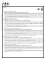
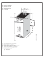
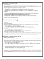
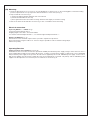
(DE) Produktabbildung
(EN) Illustrations of the product
(FR) Présentation du produit
(ES) Presentación del producto
(IT) Illustrazione del prodotto
(RU)
Внешний вид изделия
(ZH)
ׂྔႚຫ
(DE) Mindestabstände zu benachbarten Geräten
(EN) Minimum distances to other units
(FR) Distances minimales par rapports à d’autres modules
(ES) Distancia mínima con aparatos cercanos
(IT) Distanze minime rispetto agli apparecchi vicini
(RU)
Минимальное расстояние до других блоков
(ZH)
Ҿጎ้ᇑഄഗॲڦፌၭਐ
(A) = 10 mm (0.39 in)
(B) = 50 mm (1.97 in)
3

CP-...
< 20 A
CP-...
< 20 A
L+ L+ L- L-
CP-A RU
INPUT 1 INPUT 2
+ + - -
OUTPUT
+ - + -
L N PE L N PE
L1
L2
L3
N
PE
Load
2CDC 272 023 F0208
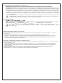
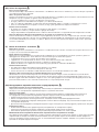
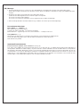
IV Echte Redundanz
> 20 A
L+ L-
CP-A RU
INPUT 1 INPUT 2
++--
OUTPUT
+-+-
L+ L-
> 20 A
L+ L-L+ L-
CP-A RU
INPUT 1 INPUT 2
++--
OUTPUT
+-+-
2CDC 272 027 F0205
Load
2CDC 272 012 F0b04
2CDC 272 013 F0b04
V Connection diagram
2CDC 272 019 F0005
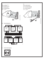
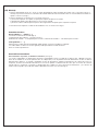
II
(DE) Produkt anbringen
(EN) Fix product
(FR) Montage du produit
(ES) Fijar el producto
(IT) Montare il prodotto
(RU)
Установка изделия
(ZH)
ׂҾጎ
III
(DE) Produkt entfernen
(EN) Remove product
(FR) Démontage du produit
(ES) Desmontar el producto
(IT) Rimuovere il prodotto
(RU)
Снятие изделия
(ZH)
ׂႂጎ
4

(DE) Sicherheits- und Warnhinweise
Anlage freischalten!
Vor Installations-, Wartungs- oder Änderungsarbeiten: Anlage spannungsfrei schalten, vor Wiedereinschalten sichern.
Vor Inbetriebnahme:
Achtung! Unsachgemäße Installation/Betrieb kann die Sicherheit beeinträchtigen und zu Betriebsstörungen oder zur Zerstörung
des Gerätes führen. Vor der Inbetriebnahme ist Folgendes sicherzustellen:
• Anschluss gemäß den landesspezifischen Vorschriften durchführen.
• Zuleitungen und Gerät ausreichend dimensionieren bzw. absichern.
• Ausgangsleitungen für den Ausgangsstrom ausreichend dimensionieren und polrichtig anschließen.
• Abstände zu benachbarten Geräten beachten (siehe Abbildung I) um eine ausreichende Kühlung zu gewährleisten
Im Betrieb:
• Keinerlei Änderungen an der Installation (primär- und sekundärseitig) vornehmen!
Gefahr von Lichtbögen und elektrischem Schlag (Lebensgefahr)!
• Verbrennungsgefahr: In Abhängigkeit der Betriebsbedingungen kann die Gehäusetemperatur hohe Werte annehmen.
Achtung: Hochspannung! Gespeicherte Energie! Gefährliche Energie am Ausgang!
In Netzteilen befinden sich Bauelemente mit hoher gespeicherter Energie und Stromkreise mit Hochspannung!
Bei einigen Geräten dieser Serie kann der Ausgang gefährlich hohe Energiemengen abgeben. Deshalb keine Gegenstände in die
nachgeschaltete Redundanzeinheit einführen und die Geräte nicht öffnen. Sicherstellen, dass Bedienpersonal vor versehentlicher
Berührung energieführender Teile geschützt ist.
(EN) Safety instructions and warnings
Disconnect system from supply network!
Before any installation, maintenance or modification work: Disconnect the system from the supply network and protect against
switching on.
Before start of operation:
Attention! Improper installation/operation may impair safety and cause operational difficulties or destruction of the unit.
Before operation the following must be ensured:
• Connect according to the specific national regulations.
• Power supply cables and unit must be sufficiently fused and rated.
• Rate the output lines sufficiently for the output current and connect them with the correct polarity.
• In order to ensure sufficient air-cooling the distance to other devices has to be considered (see figure I)
In operation:
• Do not modify the installation (primary and secondary side)!
Risk of electric arcs and electric shock (danger to life)!
• Risk of burns: Depending on the operation conditions the enclosure can become very hot
Warning: High voltage! Stored energy! Energy hazard at output!
Power supply units contain components with high stored energy and circuits with high voltage! With some units of this range the
output is capable of providing hazardous energy. Do not introduce any objects into the downstream redundancy unit, and do not
open the units. Ensure that the service personnel is protected against inadvertent contact with parts carrying energy.
(FR) Indications de sécurité et mises en garde
Mettre l’installation hors tension!
Avant le début des travaux d’installation, d’entretien ou de modification : mettre le module hors tension et s’assurer qu’il ne peut
pas être remis sous tension par erreur.
Avant la mise en service:
Attention! Une installation non adaptée peut diminuer la sécurité, provoquer des disfonctionnements et amener la destruction du
module. Avant la mise en service il faut veiller aux points suivants :
• Le raccordement doit être effectué en conformité avec les prescriptions appliquées dans le pays concerné.
• Protéger et dimensionner les câbles suffisamment.
• Tous les câbles de sortie doivent être dimensionnés suffisamment pour le courant de sortie et raccordés correctement par
rapport à la polarité.
• Considérer la distance du module aux autres modules (voir Fig. I) pour garantir un refroidissement suffisant.
Sous tension:
• Ne pas effectuer de changements (côté primaire et secondaire) quand le module est sous tension!
Risque de formation d’arcs et de chocs électriques (danger de mort!)
• Risques de brûlures: Selon les conditions d’utilisation le boîtier peut devenir très chaud.
Attention: Haute tension! Energie emmagasinée! Energie dangereuse à la sortie!
Les alimentations renferme des composants emmagasinant de l’énergie et des circuits sous haute tension! La sortie de certains
appareils peut émettre d’importantes quantités d’énergie. Ne pas introduire d’objets dans le module redondant raccordé en série
et ne pas l’ouvrir les appareils! Il faut s’assurer que le personnel de maintenance soit protegé contre les contacts accidentels avec
des composants sous tension.
5

(ES) Avisos de seguridad
Desconecte la instalación!
Antes de iniciar trabajos de instalación, mantenimiento o modificación desconecte su instalación y cerciórese de que no pueda ser
conectada nuevamente por descuido.
Antes de la puesta en marcha:
Atención! Una instalación incorrecta o uso inadecuado puede afectar a la seguridad y al funcionamiento, hasta la destrucción total
del aparato. Hay que comprobar lo siguiente antes de la puesta en marcha:
• La conexión debe hacerse conforme a las disposiciones nacionales.
• Proteger y dimensionar adecuadamente el aparato y los cables de alimentación.
• Todos los cables de salida deben ser adecuados para la intensidad de salida y conectados con polarización correcta.
• Tener en cuenta la distancia con aparatos cercanos (ver Fig. I) para garantizar una refrigeración suficiente.
Durante el funcionamiento:
• En ningún caso efectuar modificaciones de la instalación (lado primario y secundario)!
Peligro de arcos voltáicos y choques eléctricos (peligro de muerte)!
• Peligro de quemaduras: Dependiendo de las condiciones de funcionamiento, la caja puede alcanzar temperaturas elevadas
Atención: Alta tensión! Energía acumulada! Riesgo de energía en los terminales de salida!
Fuentes de alimentación contienen conductores no protegidos bajo alta tensión, así como componentes que acumulan energía
elevada! En algunos dispositivos de esta serie, la salida puede emitir intensidades de energía peligrosas. No introducir objetos
en el módulo redundante postconectado y no abrir los aparatos. Es necesario la protección del personal de servicio, para evitar
contactos accidentales.
(IT) Norme di sicurezza e avvertenze
Disinserire il sistema!
Prima di eseguire lavori di installazione, manutenzione o modifica, disinserire il sistema, assicurarsi che sia privo di tensione e che
non possa essere reinserita inavvertitamente.
Prima della messa in funzione:
Attenzione! La scorretta installazione e il funzionamento inadeguato possono pregiudicare la sicurezza e portare a guasti e al
danneggiamento del dispositivo. Prima della messa in funzione bisogna accertarsi del seguente:
• Il collegamento deve essere conforme alle specifiche norme nazionali.
• L’apparecchio e i cavi d’alimentazione devono essere sicuri e dimensionati in modo sufficiente.
• Dimensionare tutti i cavi d’uscita idoneamente e collegarli con giusta polarità.
• Badare alle distanze verso apparecchi vicini (vedere Fig. I) per garantire un sufficiente raffredamento.
Durante il funzionamento:
• Non apportare modifiche all’installazione (parte primaria e secondaria)!
Pericolo di arco voltaico e shock di corrente (Pericolo di morte)!
• Pericolo di ustioni: A seconda delle condizioni di funzionamento, la custodia può diventare molto calda.
Attenzione: Alta tensione! Energia accumulata! Energia pericolosa all’uscita!
Gli alimentatori sono provvisti di componenti che accumulano moltissima energia, nonché di conduttori non protetti ad alta
tensione! In alcuni apparecchi di questa serie l’uscita può emettere pericolosamente elevati quantitativi di energia. Perciò non
introdurre oggetti nel modulo ridondante collegato in serie e non aprire gli apparecchi. Provvedere alla adeguate protezione del
personale di manutenzione contro eventuali contatti fortuiti con componenti portando energia.
(RU) Инструкции по мерам безопасности и предупреждения
Отключайте систему от сети электропитания!
Перед выполнением любых работ по монтажу, техническому обслуживанию или модернизации отключайте
систему от сети электропитания и принимайте меры от случайного включения.
Перед началом работ:
Внимание! Неправильная установка и эксплуатация устройства может привести к нарушению мер безопасности
и к затруднению эксплуатации или разрушению изделия. Перед началом эксплуатации убедитесь в том, что:
• Подключение выполнено в соответствии с национальными требованиями.
• Кабели электропитания и сам блок должны быть защищены соответствующими предохранителями.
• Номинальные параметры отводящих линий должны соответствовать выходному току блока питания и подключаться с
соблюдением полярности.
• Для обеспечения необходимого охлаждения изделия следует соблюдать расстояния до других устройств (см. Рисунок I)
В процессе работы:
• Не вносите изменения в конструкцию изделия (как первичной, так и вторичной стороне)!
Существует риск дугового разряда и поражения электрическим током (опасно для жизни)!
• Риск ожогов: при некоторых условиях эксплуатации кожух изделия может быть очень горячим
Внимание! Высокое напряжение! Накопление энергии! Опасное напряжение на выходе!
Источники питания содержат компоненты, которые способны накапливать значительную энергию, а также цепи с высоким
напряжением! На выходе источников питания возможны опасные уровни энергии. Не вставляйте никакие предметы в
блок и не разбирайте блоки. Убедитесь в том, что обслуживающий персонал надежно защищен от случайного контакта с
деталями, по которым передается энергия.
6

(ZH)
!Ҿඇኸళᇑጀᅪ๚ၜ
ᇑࠃۉဣཥਸƽ
ሞඪࢆҾጎĂྼࢺࢅႪ߀ኮമǖॽఇᇑࠃۉဣཥਸLjժՆ௨ԥဃฉۉă
ਸ๔߾ፕമǖ
ጀᅪƽҾጎ0֡ፕփኟඓీࣷᆖၚఇڦҾඇႠLjڞዂ߾ፕփኟLj࣋ఇăᅺُሞਸ๔߾ፕമLjՂႷԍኤǖ
• ۉഘথՂႷӀቷ༬ۨڦࡔॆՔጚྜׯă
• ࠃۉۉમࢅఇԥභഗᆶၳႜԍࢺLjሞܮۨኵᅜాă
• ߵۉୁስܮۨڦۉમLjժԍኤटႠথኟඓă
• ྺକඓԍഘૐඐᆶၳLjႴ୯ࢅ၎ତఇڦक़ਐDŽ֖९!
I
Dž!
߾ፕዐǖ
• փሎႹ߸߀ҾጎDŽᅃْ֨ࢅْܾ֨Džƽ!!
ᆶۉࢷࢅۉऍླ၃DŽླतิంDžƽ
• ጤฅླ၃ǖሏႜཉॲփཞLjఇڦྔీݥඤă!
য়ߢǖߛۉუƽټీଉئ٪ƽ֨ᆶీଉዂླ၃ƽ
ۉᇸఇాևټ٪ئᆶߛీଉڦഗॲLj࣮ୟټߛۉუƽ!ఇీዂླ၃ڦీଉăჹ্ሞරᇆఇዐݣഄLjჹ্ٶਸఇ
ྔă൩ඓණޜခටᇵᅜՆ௨ᅺࢮܸಸةڟߛీଉഗॲ
7

(DE) Montage:
1. DIN-Schiene (TH 35-15 oder TH 35-7.5 nach IEC/EN 60715) wie in Abbildung I dargestellt auf der Montageplatte befestigen,
horizontale Einbaulage, Eingangsklemmen oben, die Mindestabstände (siehe Abbildung I) zu benachbarten Geräten einhalten.
2. Gerät wie in Abbildung II dargestellt auf die DIN-Schiene aufschnappen.
1) Gerät leicht nach oben kippen und auf DIN-Schiene aufsetzen.
2) Bis zum Anschlag nach unten klappen.
3) Unten gegen die Vorderseite drücken, um zu verriegeln. Leicht am Gerät rütteln, um Verriegelung zu überprüfen.
3. Entfernen von der DIN-Schiene wie in Abbildung III dargestellt. Schraubendreher zur Entriegelung verwenden.
Elektrischer Anschluss:
Eingangsseite [INPUT 1 + - / INPUT 2 + -]:
Elektrische Verbindung der Eingangsklemmen herstellen (Abbildung V))
Abisolierlänge der Leitungen - siehe technische Daten
Linke Eingangsklemmen + - für Kanal 1, rechte Eingangsklemmen + - für Kanal 2
Ausgangsseite [OUTPUT + + - -]:
Leitungen nach maximalem Ausgangsstrom dimensionieren oder gesonderte Absicherung vorsehen.
Um Spannungsabfälle zu minimieren wird empfohlen die Querschnitte so groß wie möglich zu wählen.
Polung beachten.
Betrieb/Funktion:
Parallelbetrieb, echte Redundanz: (siehe Abbildung IV)
Um bei Fehlern (z.B. in der Verdrahtung, Auslösen der Sicherung im Primärstromkreis, Defekt einzelner Geräte) eine höhere
Verfügbarkeit zu erreichen, können Stromversorgungen redundant aufgebaut werden. Tritt im ersten Stromversorgungskreis ein
Fehler auf (sog. Erstfehler), wird die Stromversorgung aller Verbraucher vom zweiten, redundanten Versorgungskreis übernom-
men. Hierzu werden die parallel zu schaltenden Stromversorgungen so dimensioniert, dass der Gesamtstrombedarf aller
angeschlossenen Verbraucher von einer Stromversorgung vollständig abgedeckt werden kann, und die Ausgangskreise werden,
wie in Abbildung IV dargestellt, mit der Redundanzeinheit CP-A RU voneinander entkoppelt.
8

(EN) Mounting:
1. Fasten the DIN rail (TH 35-15 or TH 35-7.5 acc. IEC/EN 60715) as shown in Fig. I on the mounting plate, horizontal mounting
position, input terminals on top, respect the minimum distance to other units (see Fig. I)
2. Snap on DIN rail as shown in Fig. II
1) Tilt the unit slightly upwards and fit the unit on the DIN rail
2) Lift it downward until it hits the stop
3) Press against the bottom front side for locking. Shake the unit slightly to check the locking
3. Remove the unit from the DIN rail as shown in Fig. III. Use a screwdriver for the unlocking.
Electrical connection:
Input side [INPUT 1 + - / INPUT 2 + -]:
Connect the input terminals (Fig. V)
Stripping length of the cable – see technical data
For channel 1 left-hand input terminals + -, for channel 2 right-hand input terminals + -
Output side [OUTPUT + + - -]:
Rate the lines for the maximum output current or provide a separate fuse protection.
We recommend choosing the cable cross section as large as possible in order to minimize voltage drops.
Observe the polarity.
Operating/Function:
Parallel operation, true redundancy: (see Fig. IV)
Redundant circuits are used to increase the operational reliability and eliminate power supply outages. Events that can cause a
power supply failure include: incorrect wiring, blown fuses, or failure of a single power supply. If a fault event occurs (called initial
fault) in the first power supply circuit, power to all loads is then supplied by the second, redundant power supply. For this reason,
both power supplies must be sized to handle the total current requirement of all loads. The primary and the redundant power
supplies are decoupled from one another by the CP-A RU unit, as shown in Fig. IV.
9

(FR) Montage:
1. Fixer le profilé DIN (TH 35-15 ou TH 35-7.5 selon IEC/EN 60715) sur la platine de montage comme décrit dans la Fig. I,
position de montage horizontale, bornes d’entrée en haut, observer les distances minimales (voir Fig. I) par rapports à d’autres
modules.
2. Encliqueter le module sur le profilé DIN comme décrit dans la Fig. II
1) Basculer le module légèrement vers le haut et le placer sur le profilé
2) Pousser vers le bas jusqu’à la butée
3) Pousser vers l’avant pour encliqueter. Secouer légèrement pour vérifier l’encliquetage
3. Démonter du profilé DIN comme décrit dans la Fig. III. Utiliser un tournevis pour le désencliquetage.
Raccordement électrique:
Entrée [INPUT 1 + - / INPUT 2 + -]:
Raccorder les bornes d’entrée (Fig. V)
Longueur des câbles à dénuder – voir Données Techniques
Bornes d’entrée + - à gauche pour la voie 1, bornes d’entrée + - à droitepour la voie 2
Sortie [OUTPUT + + - -]:
Dimensionner les lignes pour le courant de sortie maximum ou les protéger par un fusible spécial.
Choisir des câbles de grande section, afin de réduire au minimum les chutes de tension.
Faire attention à la polarité.
Opération/Fonctionnement:
Fonctionnement en parallèle, vraie redondance: (voir Fig. IV)
Pour arriver à une fiabilité de fonctionnement plus élevée en cas d’erreurs (p.e. en câblage, déclenchement du fusible dans le
circuit primaire, défaut d’un module unique), on peut monter des circuits redondants. En cas de défaut dans le circuit primaire
de la première alimentation (dit premier erreur), le second cicuit redondant prend le relais pour assurer l’alimentation de tous les
consommateurs. Pour cela, les alimentations à brancher en parallèle doivent être dimensionnées de manière à ce qu’un seul
module puisse couvrir intégralement la demande totale en courant de tous les appareils consommateurs, et les circuits de sortie
sont découplés, comme décrit dans la Fig. IV, avec le module redondant CP-A RU.
10

(ES) Montaje:
1. Fijación del perfil DIN (TH 35-15 ó TH 35-7.5 según IEC/EN 60715) sobre una placa de montaje como se muestra en la Fig. 1,
montaje en posición horizontal, los terminales de entrada deben de estar hacía arriba, tener en cuenta la distancia mínima con
aparatos cercanos (ver Fig. I)
2. Fijación del aparato en el perfil como se muestra en la Fig. II
1) Posicionar el aparato en el perfil, encajar la parte superior de fijación en el perfil
2) Desplazar el aparato hacía abajo para su colocación en el perfil
3) Presionar sobre la cubierta para su fijación. Mover ligeramente el aparato para comprobar su fijación
3. Para desmontar el aparato se utiliza un destornillador como se muestra en la Fig. III.
Conexión eléctrica:
Entrada [INPUT 1 + - / INPUT 2 + -]:
Conectar los terminales de entrada (Fig. V)
Longitud a pelar del conductor - ver Datos Técnicos
Terminales de entrada + - a la izquierda para el canal 1, terminales de entrada + - a la derecha para el canal 2
Salida [OUTPUT + + - -]:
Dimensionar los cables para la intensidad de salida máxima o preveer un fusible por separado.
Los cables deben ser de la sección más grande posible para reducir la caída de tensión.
Tener en cuenta la polarización.
Servicio/Funcionamiento:
Funcionamiento en paralelo, redundancia verdadera: (ver Fig. IV)
Los circuitos redundantes se utilizan para aumentar la seguridad de servicio en caída de un defecto (p.ej. cableado incorrecto,
fusión de los fusibles en el circuito primario, fallo en el dispositivo). Si en la primaria fuente de alimentación se tiene un defecto
(llamado primer defecto), el segundo, redundante circuito de alimentación adopta la alimentación de corriente de todos los
receptores. A tal fin, las fuentes de alimentación a conectar en paralelo se dimensionan de forma, que el consumo de corriente
total de todos los receptores conectados se pueda cubrir por completo por una sola fuente de alimentación, y los circuitos de
salida son desacoplados por medio del módulo redundante CP-A RU, como muestra Fig. IV.
11

(IT) Montaggio:
1. Fissare la barra DIN (TH 35-15 o TH 35-7.5 in conformità con IEC/EN 60715) come descritto nella Fig. I sulla piastra di
montaggio, montare in posizione orizzontale, morsetti d’ingresso in alto, osservare le distanze minime (vedere Fig. I) rispetto gli
apparecchi vicini.
2. Applicare l’apparecchio come descritto nella Fig. II sulla guida di supporto
1) Tenere l’apparecchio leggermente inclinato verso l’alto, poggiarlo sul supporto sagomato
2) Premere verso il basso fino alla battuta
3) Spingere in avanti premendo in basso fino ad avvenuto arresto. Verificarne la stabilità scrollandolo leggermente
3. Rimuovere l’apparecchio dalla guida di supporto come descritto nella Fig. III. Usare un cacciavite per lo sbloccaggio.
Collegamento elettrico:
Ingresso [INPUT 1 + - / INPUT 2 + -]:
Collegare i morsetti d’ingresso (Fig. V)
Lunghezza della spelatura - vedere Dati Tecnici
Morsetti d’ingresso + - a sinistra per il canale 1, morsetti d’ingresso + - a destra per il canale 2
Uscita [OUTPUT + + - -]:
Dimensionare le linee a secondo della corrente d’uscita massima oppure prevedere una protezione separata.
Per minimizzare cadute di tensione raccomandiamo di scegliere delle sezioni più grandi possibile.
Considerare la polarità.
Operazione/Funzionamento:
Funzionamento in parallelo, vera ridondanza: (vedere Fig. IV)
Per aumentare l’affidabilità di funzionamento in caso di errori (p.e. di cablaggio, scatto del fusibile nel circuito di corrente
primario, difetto di un apparecchio singolo), si può costruire un circuito di corrente ridondante. Se sorge un difetto nel
primo circuito di alimentazione di corrente (cosiddetto primo errore), il secondo, ridondante circuito di alimentazione s’incarica
dell’alimentazione di corrente di tutti i carichi. Perciò è necessario dimensionare gli alimentatori da collegare in parallelo in modo
che il consumo di corrente totale di tutti i carichi collegati possa essere coperto completamente da un solo alimentatore. Bisogna
anche disaccoppiare i circuiti di uscita l’uno dall’altro, come descritto nella Fig. IV, mediante il modulo ridondante CP-A RU.
12

(RU)
Монтаж:
1. Установите DIN рейку (TH 35-15 или TH 35-7,5 согласно стандарту IEC/EN 60715) как показано на Рисунке I, на
монтажной панели в горизонтальном положении, входные клеммы сверху, сохраняя необходимое расстояние до
других изделий (см. Рисунок I)
2. Установите изделие на DIN рейку как показано на Рисунке II
1) Слегка наклоните изделие вверх и установите его на DIN рейку
2) Потяните его вниз до упора
3) Нажмите на нижний край лицевой панели для защелки. Слегка покачайте изделие, чтобы убедиться в его надежном
креплении
3. Демонтаж устройства с DIN рейки показан на Рисунке III. Для освобождения защелки используется отвертка.
Электрическое подключение:
На стороне входа [INPUT 1 + - / INPUT 2 + -]:
Подключите входные клеммы (Рисунок V)
длина зачистки кабеля указана в технических данных зделия
Для канала 1 ' левые входные клеммы + ', для канала 2 ' правые входные клеммы + '.
На стороне выхода [OUTPUT + + - -]:
Рассчитывайте номинальные параметры линий на максимальный выходной ток или используйте отдельные
предохранители.
Мы рекомендуем выбирать кабели с наибольшим сечением для минимизации потерь напряжения.
Соблюдайте полярность.
Эксплуатация/функционирование:
Параллельная работа, резервирование: (см. Рисунок IV)
Резервирование цепей используется для увеличения эксплуатационной надежности при возникновении ошибок (таких как
неправильное включение, перегорание предохранителей в цепях первичного питания, авария отдельных устройств). Если
неисправность возникает в цепи первого источника питания (так называемая первичная неисправность), электропитание
всех потребителей будет осуществляться от второго, резервного, источника питания. По этой причине, параллельно вклю-
чаемые блоки питания должны иметь такую мощность, чтобы обеспечить одним блоком электропитание всех потребителей,
а выходные цепи разъединяются посредством модуля резервирования CP-A RU, как это показано на Рис. IV
.
13

(ZH) Ҿጎǖ
1.
!සJ๖LjఇҾጎሞ
DIN
ڞࡆฉDŽ
TH 35-15
ई
TH 35-7.5
Ljޙࢇ
IEC/EN 60715
DžLjೝҾጎLj܋ጱ࿋ᇀఇฉݛLjጀᅪᇑ
ഄఇڦፌၭक़ਐDŽ֖९
I
Dž
2.
ॽఇਸ਼ڟEJOڞࡆฉLjසJJ๖ǖ
1)
!ྲྲၠฉൡၽఇLjࢫॽኮਸ਼ڟEJOڞࡆฉ!
2)
!ၠူൟუఇ݆ူუ!
3)
!ူუఇڹևമ܋ᅜLjࢫൟࣤఇॠֱޏᅙਸ਼ሞڞࡆฉ
3.
!ٗ
DIN
ڞࡆฉָႂఇLjස
III
ă๑ᆩᅃӝஅີژॽఇٗڞࡆฉਸă
ۉഘথǖ
܋
[INPUT 1 + - / INPUT 2 + -]:
থ܋ጱDŽ֖९
V
Dž
ڞ၍Ԋ၍܈!..!൩֖९रຍ֖ຕ
ཚڢ
1
ǖፑ֨܋ጱ
+ -
Ǘཚڢ
2
ǖᆸ֨܋ጱ
+ -
܋
[OUTPUT + + - -]:
ߵፌٷۉୁઠስڞ၍Ljई༵ࠃڇ܀ڦභഗԍࢺă
்ॺᅱስీٷপ௬ओڦڞ၍Ljᅜ३ณუইă
ጀᅪटႠă
! ሏႜ0ࠀీǖ
ժ߾ፕLjኈරᇆǖDŽ֖९
IV
Dž
රᇆ࣮ୟᆩᇀሺे߾ፕڦ੍Ⴀࢅ३ณࠃۉዐ൧ăీڞዂࠃۉࠤቱڦ൧ᆶǖথٱ၍ĂභഗฏۖĂగ߲ۉᇸࠤቱڪăැڼ
ᅃ߲ۉᇸ࣮ୟ݀ิࠤቱDŽྺ؛๔ࠤቱDžLjሶᆶሜڦࠃۉᆯڼ
2
߲ۉᇸ༵ࠃLjनරᇆࠃۉăᆯᇀኄ߲ᇱᅺLjժۉᇸڦࠀ୲ስ
ՂႷጀᅪǖᆶሜڦۉୁႴ൱ᆯ
1
߲ۉᇸఇྜඇࠃᆌă߲ࢅරᇆۉᇸཚࡗ
CP-A RU
၎ࢻ᳘Ljස
IV
๖ă
14

15

1) incl. lateral screw
2) This device is designed for connection to a safety extra-low voltage source. If no safety extra-low voltage is used at the input side, the lateral screw can be
used for grounding of the enclosure (protection class I).
3) According to UL this is the surrounding air temperature
When used use in combination with other power supplies than modules ABB series CP-S and CP-C, each input circuitry
shall be provided with overcurrent protection, Circuit breaker - Listed (DIVQ) Type S201 DC-K 6, manufactured by ABB
STOTZ-KONTAKT GmbH. Rated 60 Vdc, 6A
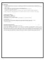
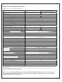
Technical data - Redundancy unit CP-A RU
Data at T
a
= 25
o
C, unless otherwise indicated
Type CP-A RU CP-A RU
in combination with CP-A CM
Input (+, -, +, -)
Rated input voltage U
in
24 V DC
Input voltage range per channel 10-28 V DC 13-28 V DC
Rated input current per channel
1-20 A
Max. input current per channel
30 A for 300 s
Transient overvoltage protection
yes
Output (L+, L+, L-, L-)
Rated output voltage U
out
24 V DC
Voltage drop
typ. 0.6 V, max. 0.9 V
Rated output current I
out
1-40 A
Output ratings per channel at T
a
= 60 °C
10-28 V DC / 40 A 13-28 V DC / 40 A
at T
a
= 70 °C
10-28 V DC / 30 A 13-28 V DC / 30 A
Derating
60 °C < T
a
<
70 °C
2.5 % per Kelvin temperature increase
Peak output current
60 A for 300 s
Resistance to reverse feed
< 40 V
General data
Mounting DIN rail (TH 35-15 or TH 35-7.5 acc. to IEC/EN 60715),
snap-on mounting without any tool
Mounting position
horizontal
Minimum distance to other units, horizontal/vertical
10 mm / 50 mm (0.39 in / 1.97 in)
Degree of protection housing / terminals
IP20 / IP20
Material of enclosure housing shell / cover
aluminium / zinc-coated sheet steel
Protection class ( EN 61140)
III
2)
Electrical connection
Wire size
fine-strand with wire end ferrule
2.5-10 mm
2
(14-8 AWG)
fine-strand without wire end ferrule
0.5-10 mm
2
(20-8 AWG)
rigid 0.5-16 mm
2
(20-6 AWG)
Stripping length
12 mm (0.47 in)
Tightening torque
1.2-1.5 Nm
Environmental data
Ambient temperature range
3)
operation -25...+70 °C (-13...+158 °F)
storage -40...+85 °C (-40...+185 °F)
Damp heat (IEC/EN 60068-2-3)
93 % at +40 °C, no condensation
Climatic class (IEC/EN 60721)
3K3
Isolation data
Insulation voltage input / output / housing 500 V AC (routine test)
Pollution degree (EN 50178)
2
16
-
 1
1
-
 2
2
-
 3
3
-
 4
4
-
 5
5
-
 6
6
-
 7
7
-
 8
8
-
 9
9
-
 10
10
-
 11
11
-
 12
12
-
 13
13
-
 14
14
-
 15
15
-
 16
16


ABB CP-A RU Istruzioni per l'uso
- Categoria
- Proteggi cavi
- Tipo
- Istruzioni per l'uso
- Questo manuale è adatto anche per
in altre lingue
- English: ABB CP-A RU Operating instructions
- français: ABB CP-A RU Mode d'emploi
- español: ABB CP-A RU Instrucciones de operación
- Deutsch: ABB CP-A RU Bedienungsanleitung
- русский: ABB CP-A RU Инструкция по эксплуатации
Documenti correlati
-
ABB CT-C Series Istruzioni per l'uso
-
-
-
ABB CM Series Istruzioni per l'uso
-
-
-
-
-
-