Allied Telesis AT-MC13 Guida d'installazione
- Categoria
- Convertitori multimediali di rete
- Tipo
- Guida d'installazione

AT-MC13
AT-MC14
AT-MC15
AT-MC16
Ethernet Media Converters
Installation Guide
PN 613-10724-00 Rev C

Copyright 2001 Allied Telesyn International Corp.
960 Stewart Drive Suite B, Sunnyvale CA 94086 USA
All rights reserved. No part of this publication may be reproduced without prior written
permission fro
Allied Telesyn International Corp.
Ethernet is a registered trademark of Xerox Corporation. All other product names,
company names, logos or other designations mentioned herein are trademarks or
registered trademarks of their respective owners.
Allied Telesyn International Corp. reserves the right to make changes in specifications
and other information contained in this document without prior written notice. The
information provided herein is subject to change without notice. In no event shall Allied
Telesyn International Corp. be liable for any incidental, special, indirect, or
consequential damages whatsoever, including but not limited to lost profits, arising out
of or related to this manual or the information contained herein, even if Allied Telesyn
International Corp. International Corp. has been advised of, known, or should have
known, the possibility of such damages.

iii
Electrical Safety and Emission Compliance
Statement
Standards: This product meets the following standards.
U.S. Federal Communications Commission
DECLARATION OF CONFORMITY
Manufacture Name: Allied Telesyn International Corp.
Manufacture Address: 960 Stewart Drive, Suite B
Sunnyvale, CA 94085 USA
Manufacture Telephone: 408-730-0950
Declares that the product: Ethernet Media Converters
Model Numbers: AT-MC13, AT-MC14, AT-MC15, AT-MC16
This product complies with FCC Part 15B, Class B Limits:
This device complies with part 15 of the FCC Rules. Operation is subject
to the following two conditions: (1) This device must not cause harmful
interference, and (2) this device must accept any interference received,
including interference that may cause undesired operation.
RADIATED ENERGY
Note: This equipment has been tested and found to comply with the
limits for a Class B digital device pursuant to Part 15 of FCC Rules.
These limits are designed to provide reasonable protection against
harmful interference in a residential installation. This equipment
generates, uses and can radiate radio frequency energy and, if not
installed and used in accordance with instructions, may cause harmful
interference to radio or television reception, which can be determined by
turning the equipment off and on. The user is encouraged to try to correct
the interference by one or more of the following measures:
- Reorient or relocate the receiving antenna.
- Increase the separation between the equipment and the receiver.
- Connect the equipment into an outlet on a circuit different from that to
which the receiver is connected.
- Consult the dealer or an experienced radio/TV technician for help.
Changes and modifications not expressly approved by the manufacturer
or registrant of this equipment can void your authority to operate this
equipment under Federal Communications Commission rules.
Industry Canada
This Class B digital apparatus meets all requirements of the Canadian
Interference-Causing Equipment Regulations.
Cet appareil numérique de la classe B respecte toutes les exigences du
Règlement sur le matériel brouilleur du Canada.

iv
Warning: In a domestic environment this product may cause radio
interference in which case the user may be required to take adequate
measures.
RFI Emission EN55022 Class B
$ 1
Immunity EN55024 $ 2
Warning (AT-MC13, AT-MC14, AT-MC16): This product requires shielded cables to
comply with emission and immunity standards. If it is used with unshielded
cables, the user may be required to take measures to correct the interference
problem at their own expense.
$ 3
Electrical Safety TUV-EN60950, UL1950, CSA 950
$ 4
Laser EN60825 $ 5
Important: Appendix B contains translated safety statements for installing
this equipment. When you see the
$, go to Appendix B for the translated
safety statement in your language.
Wichtig: Anhang B enthält übersetzte Sicherheitshinweise für die
Installation dieses Geräts. Wenn Sie
$ sehen, schlagen Sie in Anhang B den
übersetzten Sicherheitshinweis in Ihrer Sprache nach.
Vigtigt: Tillæg B indeholder oversatte sikkerhedsadvarsler, der vedrører
installation af dette udstyr. Når De ser symbolet
$, skal De slå op i tillæg B
og finde de oversatte sikkerhedsadvarsler i Deres eget sprog.
Belangrijk: Appendix B bevat vertaalde veiligheidsopmerkingen voor het
installeren van deze apparatuur. Wanneer u de
$ ziet, raadpleeg Appendix
B voor vertaalde veiligheidsinstructies in uw taal.
Important: L'annexe B contient les instructions de sécurité relatives à
l'installation de cet équipement. Lorsque vous voyez le symbole
$, reportez-
vous à l'annexe B pour consulter la traduction de ces instructions dans votre
langue.
Tärkeää: Liite B sisältää tämän laitteen asentamiseen liittyvät käännetyt
turvaohjeet. Kun näet
$-symbolin, katso käännettyä turvaohjetta liitteestä
B.
Importante: l’Appendice B contiene avvisi di sicurezza tradotti per
l’installazione di questa apparecchiatura. Il simbolo
$, indica di consultare
l’Appendice B per l’avviso di sicurezza nella propria lingua.
Viktig: Tillegg B inneholder oversatt sikkerhetsinformasjon for installering
av dette utstyret. Når du ser
$, åpner du til Tillegg B for å finne den
oversatte sikkerhetsinformasjonen på ønsket språk.
Importante: O Anexo B contém advertências de segurança traduzidas para
instalar este equipamento. Quando vir o símbolo
$, leia a advertência de
segurança traduzida no seu idioma no Anexo B.
Importante: El Apéndice B contiene mensajes de seguridad traducidos para
la instalación de este equipo. Cuando vea el símbolo
$, vaya al Apéndice B
para ver el mensaje de seguridad traducido a su idioma.
Obs! Bilaga B innehåller översatta säkerhetsmeddelanden avseende
installationen av denna utrustning. När du ser
$, skall du gå till Bilaga B
för att läsa det översatta säkerhetsmeddelandet på ditt språk.

v
Table of Contents
Electrical Safety and Emission Compliance Statement . . . . . . . . . . . . iii
Welcome to Allied Telesyn . . . . . . . . . . . . . . . . . . . . . . . . . . . . . . . . . . . . . . vii
Where to Find Web-based Guides . . . . . . . . . . . . . . . . . . . . . . . . . . . . . . . . . vii
Document Conventions . . . . . . . . . . . . . . . . . . . . . . . . . . . . . . . . . . . . . . . . . . vii
Contacting Allied Telesyn Technical Support . . . . . . . . . . . . . . . . . . . . . . . . viii
Online Support . . . . . . . . . . . . . . . . . . . . . . . . . . . . . . . . . . . . . . . . . . . . viii
Telephone and Fax Support . . . . . . . . . . . . . . . . . . . . . . . . . . . . . . . . . . viii
Technical Support E-mail Addresses . . . . . . . . . . . . . . . . . . . . . . . . . . . . .ix
Returning Products . . . . . . . . . . . . . . . . . . . . . . . . . . . . . . . . . . . . . . . . . . . . . . ix
FTP Server. . . . . . . . . . . . . . . . . . . . . . . . . . . . . . . . . . . . . . . . . . . . . . . . . . . . . ix
For Sales or Corporate Information . . . . . . . . . . . . . . . . . . . . . . . . . . . . . . . . . . x
Tell Us What You Think . . . . . . . . . . . . . . . . . . . . . . . . . . . . . . . . . . . . . . . . . . . x
Chapter 1
Overview . . . . . . . . . . . . . . . . . . . . . . . . . . . . . . . . . . . . . . . . . . . . . . . . . . . . . . 1
Key Features . . . . . . . . . . . . . . . . . . . . . . . . . . . . . . . . . . . . . . . . . . . . . . . . . . . . 3
Status LEDs. . . . . . . . . . . . . . . . . . . . . . . . . . . . . . . . . . . . . . . . . . . . . . . . . . . . . 3
MDI/MDI-X Switch . . . . . . . . . . . . . . . . . . . . . . . . . . . . . . . . . . . . . . . . . . . . . . . 4
Fiber Link Test Switch . . . . . . . . . . . . . . . . . . . . . . . . . . . . . . . . . . . . . . . . . . . . 5
Auto-negotiation . . . . . . . . . . . . . . . . . . . . . . . . . . . . . . . . . . . . . . . . . . . . . . . . . 6
MissingLink . . . . . . . . . . . . . . . . . . . . . . . . . . . . . . . . . . . . . . . . . . . . . . . . . . . . . 7
Terminator Switch (AT-MC15 Only) . . . . . . . . . . . . . . . . . . . . . . . . . . . . . . . . . 8
External AC/DC Power Adapter . . . . . . . . . . . . . . . . . . . . . . . . . . . . . . . . . 9
Network Topologies. . . . . . . . . . . . . . . . . . . . . . . . . . . . . . . . . . . . . . . . . . . . . . 10
Standalone Topology . . . . . . . . . . . . . . . . . . . . . . . . . . . . . . . . . . . . . . . . . 10
Back-to-Back Topology . . . . . . . . . . . . . . . . . . . . . . . . . . . . . . . . . . . . . . . 11
Chapter 2
Installing the Media Converter . . . . . . . . . . . . . . . . . . . . . . . . . . . . . . . . . 13
Verifying Package Contents . . . . . . . . . . . . . . . . . . . . . . . . . . . . . . . . . . . . . . . 13
Planning the Installation . . . . . . . . . . . . . . . . . . . . . . . . . . . . . . . . . . . . . . . . . 13
Reviewing Safety Precautions . . . . . . . . . . . . . . . . . . . . . . . . . . . . . . . . . 15
Installing the Media Converter . . . . . . . . . . . . . . . . . . . . . . . . . . . . . . . . . . . . 16
Warranty Registration . . . . . . . . . . . . . . . . . . . . . . . . . . . . . . . . . . . . . . . . . . . 17

vi
Chapter 3
Troubleshooting . . . . . . . . . . . . . . . . . . . . . . . . . . . . . . . . . . . . . . . . . . . . . . . 19
Appendix A
Technical Specifications . . . . . . . . . . . . . . . . . . . . . . . . . . . . . . . . . . . . . . . 23
Physical . . . . . . . . . . . . . . . . . . . . . . . . . . . . . . . . . . . . . . . . . . . . . . . . . . . . . . 23
Temperature . . . . . . . . . . . . . . . . . . . . . . . . . . . . . . . . . . . . . . . . . . . . . . . . . . 23
Electrical Rating . . . . . . . . . . . . . . . . . . . . . . . . . . . . . . . . . . . . . . . . . . . . . . . 23
Agency Certifications. . . . . . . . . . . . . . . . . . . . . . . . . . . . . . . . . . . . . . . . . . . . 24
Appendix B
Translated Safety and Emission Information. . . . . . . . . . . . . . . . . . . . . 25
Appendix C
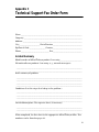
Technical Support Fax Order Form . . . . . . . . . . . . . . . . . . . . . . . . . . . . . 39
Incident Summary. . . . . . . . . . . . . . . . . . . . . . . . . . . . . . . . . . . . . . . . . . . . . . 39

vii
Welcome to Allied Telesyn
This guide contains instructions on how to install the AT-MC1x Series
Ethernet Media Converters.
Where to Find Web-based Guides
The Allied Telesyn web site at www.alliedtelesyn.com provides you with an
easy way to access the most recent documentation and technical information
for all of our products. For product guides, you can go directly to the following
web page: www.alliedtelesyn.com/support/prd_libs.htm.
Document Conventions
This guide uses several conventions that you should become familiar with first
before installing the product.
Note
A note provides additional information.
Caution
A caution indicates that performing or omitting a specific action may
result in equipment damage or loss of data.
Warning
A warning indicates that performing or omitting a specific action may
result in bodily injury.

Welcome to Allied Telesyn
viii
Contacting Allied Telesyn Technical Support
You can contact Allied Teleysn technical support online or by telephone, fax, or
e-mail.
Online Support
You can request technical support online by filling out the Online Technical
Support Form at www.alliedtelesyn.com/support/supportf.asp or by
accessing the Technical Support Knowledge Base from Allied Telesyn’s North
American web site. You can use the Knowledge Base to submit questions to our
technical support staff and review answers to previously asked questions.
Telephone and Fax Support
For Technical Support via fax, please fill out the “Technical Support Fax
Order” on page 35 and send it to the appropriate location listed below.
Americas
United States, Canada, Mexico,
Central America, South America
Tel: 1 (800) 428-4835, option 4
Fax: 1 (425) 481-3790
Germany
Germany, Switzerland, Austria, Eastern
Europe
Tel: (+49) 30-435-900-126
Fax: (+49) 30-435-70-650
Asia
Singapore, Taiwan, Thailand, Malaysia,
Indonesia, Korea, Philippines, China,
India, Hong Kong
Tel: (+65) 3815-612
Fax: (+65) 3833-830
Italy
Italy, Spain, Portugal, Greece, Turkey,
Israe
l
Tel: (+39) 02-41-30-41
Fax: (+39) 02-41-30-42-00
Australia
Tel: 1 (800) 000-880
Fax: (+61) 2-9438-4966
Japan
Tel: (+81) 3-3443-5640
Fax: (+81) 3-3443-2443
France
France, Belgium, Luxembourg,
The Netherlands, Middle East, Africa
Tel: (+33) 0-1-60-92-15-25
Fax: (+33) 0-1-69-28-37-49
United Kingdom
United Kingdom, Denmark, Norway,
Sweden, Finland
Tel: (+0044) 1235-442500
Fax: (+44) 1-235-442680

AT-MC1x Series Installation Guide
ix
Technical Support E-mail Addresses
United States and Canada
TS1@alliedtelesyn.com
Latin America, Mexico, Puerto Rico, Caribbean, and Virgin Islands
latin_america@alliedtelesyn.com
Europe
support_europe@alliedtelesyn.com
Returning Products
Products for return or repair must first be assigned a Return Materials
Authorization (RMA) number. A product sent to Allied Telesyn without a RMA
number will be returned to the sender at the sender’s expense.
To obtain an RMA number, contact Allied Telesyn’s Technical Support at one
of the following locations:
FTP Server
If you need management software for an Allied Telesyn managed device and
you know the file name of the software, you can download the software by
connecting directly to our FTP server at ftp.alliedtelesyn.com. At login,
enter ‘anonymous’ as the user name and your e-mail address for the password.
North America
Toll-free: 1-800-428-4835, option 4
Fax: 1-425-481-3790
Europe, Africa, and the Middle East
Tel: +44-1793-501401
Fax: +44-1793-431099
Latin America, the Caribbean, and
Virgin Islands
Tel: international code + 425-481-3852
Fax: international code + 425-481-3895
Puerto Rico
Tel: 1-800-424-5012, ext 3852 or
1-800-424-4284, ext 385
2
Mexico
Toll-free: 800-424-5012, ext 3852
Fax: international code + 425-481-3895
Asia and Southeast Asia
Tel: +65-381-5612
Fax: +65-383-3830
Australia
Toll-free: 1-800-000-880
Fax: +61-2-9438-4966
New Zealand
Toll-free: 0800-45-5782

Welcome to Allied Telesyn
x
For Sales or Corporate Information
You can contact Allied Telesyn for sales or corporate information at one of the
locations below:
Allied Teleyn International Corp.
19800 North Creek Parkway, Suite 200
Bothell, WA 98011
Tel: 1 (425) 487-8880
Fax: 1 (425) 489-9191
Allied Telesyn International Corp.
960 Stewart Drive, Suite B
Sunnyvale, CA 94085
Tel: 1 (800) 424-4284 (US and Canada)
Fax: 1 (408) 736-0100
Tell Us What You Think
If you have any comments or suggestions on how we might improve this or
other Allied Telesyn documents, please fill out the Send Us Feedback Form at
www.alliedtelesyn.com/contact/feedbackf.asp.

1
Chapter 1
Overview
The AT-MC1x Series Ethernet Media Converters includes the following
models:
These media converters are designed to extend the distance of your network by
interconnecting twisted pair cabling to single-mode or multimode fiber optic
cabling or thinnet cabling. The AT-MC1x Series Media Converters allow you to
interconnect LAN devices over large distances.
The AT-MC13, AT-MC14, and AT-MC16 media converters feature a 10Base-T
twisted pair port and a 10Base-F fiber optic port. The twisted pair port has an
RJ-45 connector and a maximum operating distance of 100 meters (328 feet).
The fiber optic port has an ST or SC connector and a maximum operating
distance of 2 kilometers (1.2 miles) to 100 kilometers (62 miles), depending on
the model. These media converters operate at 10 Mbps and feature half- and
full-duplex operation.
The AT-MC15 features a 10Base-T twisted pair port and a 10Base2 thinnet
port. The twisted pair port has an RJ-45 connector and a maximum operating
distance of 100 meters (328 feet). The thinnet port has a BNC-type connector
and a maximum operating distance of 185 meters (606 feet). The AT-MC15
operates at 10 Mbps and features half-duplex operation.
The AT-MC1x Series Media Converters can be used on a desktop or in an
AT-MCR12 chassis. These media converters are easy to install and do not
require software configuration or management.
q AT-MC13 q AT-MC15
q AT-MC14 q AT-MC16

2
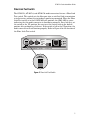
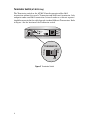
Figure 1 illustrates an AT-MC1x Series Media Converter.
Figure 1 AT-MC1x Series Media Converter (AT-MC13 model)
Table 1 lists the maximum operating distances for the AT-MC13, AT-MC14,
and the AT-MC16 media converters.
Table 1 Maximum Operating Distances
Table 2 lists the maximum operating distances for the AT-MC15 media
converter.
Table 2 Maximum Operating Distances
Model
10Base-F 10Base-T
Connector
Maximum Operating
Distance
1
1. Maximum operating distance may be less depending on the duplex mode of the end stations and the type of fiber
optic cabling used with the port.
Connector
Maximum Operating
Distance
AT-MC13 ST 2 km (1.2 mi) RJ-45 100 m (328 ft)
AT-MC14 SC 2 km (1.2 mi) RJ-45 100 m (328 ft)
AT-MC16 ST 15 km (9.3 mi) RJ-45 100 m (328 ft)
Model
10Base2 10Base-T
Connector
Maximum Operating
Distance
Connector
Maximum Operating
Distance
AT-MC15 BNC 185 m (606 ft) RJ-45 100 m (328 ft)
10Base-F
REC
LNK
TX RX
MC13 ETHERNET MEDIA CONVERTER
MDI MDI-X
10Base-T
REC
LNK
PWR
NML
FIBER
LINK TEST

AT-MC1x Series Installation Guide
3
Key Features
The media converters have the following key features:
q LEDs for unit and port status
q Full- or half-duplex mode operation (except AT-MC15)
q Half-duplex mode operation (AT-MC15 only)
q MissingLink notifies end-nodes of link failures (fiber models only)
q Link Test feature performs a link test on the media converter’s fiber
port
q MDI/MDI-X switch that eliminates the need for a crossover cable
q Internal termination on the BNC port (AT-MC15 only)
q External AC/DC power adapter
q Standard, compact size for desktop use or in an AT-MCR12 rackmount
chassis
Status LEDs
Table 3 lists the status LEDs for the AT-MC1x Series Media Converters.
Table 3 Status LEDs for the Media Converters
LED Color Description
All Models
PWR Green Power is applied to the media converter.
LNK Green A link has been established on the port.
REC Green Data is being received.
AT-MC13, AT-MC14 and AT-MC16 only
NML Green
OFF
The MissingLink feature is enabled and the media converter is
functioning in normal operating mode.
The MissingLink feature is disabled and the media converter is
performing a link test.

4
MDI/MDI-X Switch
An RJ-45 port on a 10 Mbps Ethernet network device can have one of two
possible wiring configurations: MDI or MDI-X. The RJ-45 port on a PC, router
or bridge is typically wired as MDI, while the twisted pair port on a switch or
hub is usually MDI-X.
To connect two 10 Mbps network devices together that have dissimilar port
wiring configurations, such as MDI to MDI-X, you use a straight-through cable.
To connect two network devices that have an RJ-45 port with the same wiring
configuration, such as MDI to MDI, you use a crossover cable.
The RJ-45 port on the media converters feature an MDI/MDI-X button. You can
use this button to configure the twisted pair port on the media converter as
either MDI or MDI-X, thus eliminating the need for a crossover cable
regardless of the type of network device you are connecting to the unit.
Table 4 lists the pinouts of the RJ-45 ports for both MDI and MDI-X wiring
configurations.
Table 4 RJ-45 Pinout
AT-MC15 Only
TX Green Data is being transmitted on the BNC port.
RX Green Data is being received on the BNC port.
ONLINE Green The BNC port is connected to an active 10Base2 segment.
COL Green The BNC port is sensing a collision signal.
MDI Pinout MDI-X Pinout
Pin Signal Pin Signal
1 TD + 1 RD+
2TD-2RD-
3 RD+ 3 TD+
6 RD- 6 TD-
4, 5, 7, 8 N/A 4, 5, 7, 8 N/A
Table 3 Status LEDs for the Media Converters (Continued)
LED Color Description

AT-MC1x Series Installation Guide
5
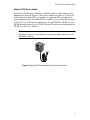
Fiber Link Test Switch
The AT-MC13, AT-MC14, and AT-MC16 media converters feature a Fiber Link
Test switch. This switch sets the fiber port into an artificial link transmission
state for testing without the twisted pair port being connected. When the Fiber
Link Test switch is in the DOWN (default) position, the NML LED is green
indicating that the media converter is functioning normally. For a link test, set
the switch in the UP position. Be sure to set the switch back to the default
position after performing a link test. If the switch is left in the UP position, the
media converter will not function properly. Refer to Figure 2 for the location of
the Fiber Link Test switch.
Figure 2 Fiber Link Test Switch
10Base-F
REC
LNK
TX RX
MC13 ETHERNET MEDIA CONVERTER
MDI MDI-X
10Base-T
REC
LNK
PWR
NML
FIBER
LINK TEST
FIBER
LINK TEST

6
Auto-negotiation
Auto-negotiation determines the duplex mode of the ports. The duplex mode
refers to the manner in which an end-node sends and receives data on the
network. Depending on its capabilities, an end-node can operate in either half-
or full-duplex mode. An end-node operating in half-duplex can either send or
receive data, but not both at the same time. However, an end-node operating
in full-duplex can send and receive data simultaneously. The best network
performance is achieved when an end-node can operate in full-duplex mode.
The AT-MC13, AT-MC14, and AT-MC16 media converters can operate in
either full- or half-duplex mode. However, it is important to note that the end-
nodes connected to these media converters must operate in the same duplex
mode to avoid a duplex mode mismatch which can result in poor network
performance.
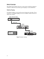
Figure 1 shows an example of a duplex mode mismatch. A repeater (Unit 1),
capable of operating in half-duplex mode only, is connected to the 10Base-F
port on the media converter, while a switch (Unit 2), capable of either half- or
full-duplex mode, is connected to the 10Base-T port on the media converter.
Figure 1 Example of a Duplex Mode Mismatch
In attempting to auto-negotiate with Unit 1, the media converter will
determine that the repeater is capable of half-duplex only and will set the port
connected to the unit appropriately. In auto-negotiating with Unit 2, the
media converter will determine that the switch can manage full-duplex and
will set the port connected to the switch to full-duplex. The result is a duplex
mode mismatch, with one unit operating in half-duplex and the other unit
operating in full-duplex. You can resolve the duplex mode mismatch by
manually configuring Unit 2, if possible, so that the port connected to the
media converter is set to half-duplex.
Unit 1
Unit 2
100Base-TX Repeater
Media Converter 100Base-TX Switch
REC
LNK
TX RX
MDI MDI-X
FIBER
LINK TEST
10Base-T
REC
LNK
PWR
NML
10Base-F

AT-MC1x Series Installation Guide
7
MissingLink
The MissingLink feature enables the ports on the media converter to pass the
“Link” status of their connections to each other. When the media converter
detects a problem with one of the ports, such as the loss of connection to a end-
node, the media converter shuts down the connection to the other port, thus
notifying the end-node that the connection has been lost.
For example, if the network twisted pair cable on an AT-MC14 were to fail, the
module would respond by dropping the link on the fiber optic port. In this way,
the AT-MC14 notifies the end-node connected to the fiber optic port that the
connection on the twisted pair port has been lost. If the failure had started with
the fiber optic cabling, the unit would drop the link to the twisted pair port.
The value to this type of network monitoring and fault notification is that some
hubs and switches can be configured to take a specific action in the event of the
loss of connection on a port. In some cases, the unit can be configured to seek a
redundant path to a disconnected end-node or send out a trap to a network
management station, alerting the network administrator of the problem.
Note
MissingLink is disabled when you perform a link test with the Fiber
Link Test switch. Consequently, to ensure that MissingLink is enabled
on the media converter, always set the Fiber Link Test switch to the
DOWN position during normal network operations.

8
Terminator Switch (AT-MC15 Only)
The Terminator switch on the AT-MC15 media converter offers 50 Ω
termination without the use of a T-connector and 50 Ω barrel terminator. Only
end-point nodes need 50 Ω termination. Internal nodes on a thinnet segment
should be connected to the cable through standard 10Base2 T-connectors. Refer
to Figure 3 for the location of the Terminator switch.
Figure 3 Terminator Switch
10Base2
MC15 ETHERNET MEDIA CONVERTER
MDI MDI-X
10Base-T
TX
RX
ONLINE
COL
RX
TX
PWR
LNK
TERMINATOR
O
F
F
O
N
TERMINATOR
O
F
F
O
N

AT-MC1x Series Installation Guide
9
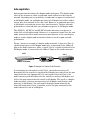
External AC/DC Power Adapter
An external AC/DC power adapter is included with the media converter for
desktop operation (see Figure 4). The power adapter supplies 12 V DC to the
media converter. Allied Telesyn supplies an approved safety compliant AC
power adapter for the 120 and 240 V AC versions with an unregulated output
of 12 V DC at 1 A. The power requirement for the AT-MC13, AT-MC14, and
AT-MC16 media converters is 12 V DC, 500 mA. The power requirement for the
AT-MC15 is 12 V DC, 300 mA
Note
The power adapter is not used if you install the media converter in an
AT-MCR12 chassis.
Figure 4 External AC/DC Power Adapter (North American Version)

10
Network Topologies
The AT-MC1x Series Media Converters can be used in two different topologies:
standalone and back-to-back. Both types of topologies are described below.
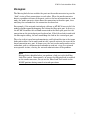
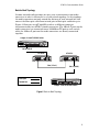
Standalone Topology
A standalone topology uses one media converter between the end-nodes. Figure
5 illustrates a standalone topology that uses an AT-MC13 media converter to
connect two switches.
Figure 5 Standalone Topology
STATUS
RESET
FAULT
RPS
PWR
10BASE-T / 100BASE-TX
FAST ETHERNET SWITCH
1
2
3
4
5
6
7
8
9
10
11
12
13
14
15
16
17
18
19
20
21
22
23
24
10BASE-T / 100BASE-TX
1X 3X 5X 7X
2X 4X 6X 8X
9X 11X 13X 15X
10X 12X 14X 16X
17X 19X 21X 23X
18X 20X 22X 24X
A
B
RS-232
TERMINAL PORT
100M LINK / ACTIVITY 10M LINK / ACTIVITY
HALF DUP/
COL
FULL DUP
PORT ACTIVITY
L/A
L/A
D/C
D/C
L/A
D/C
10Base-F
REC
LNK
TX RX
MC13 ETHERNET MEDIA CONVERTER
MDI MDI-X
10Base-T
REC
LNK
PWR
NML
FIBER
LINK TEST
AT-MC13
Fiber Optic
Twisted Pair
AT-8224XL Switch
10Base-F Fiber Optic Switch
2 km (1.2 mi)
100 m (328 ft)
La pagina si sta caricando...
La pagina si sta caricando...
La pagina si sta caricando...
La pagina si sta caricando...
La pagina si sta caricando...
La pagina si sta caricando...
La pagina si sta caricando...
La pagina si sta caricando...
La pagina si sta caricando...
La pagina si sta caricando...
La pagina si sta caricando...
La pagina si sta caricando...
La pagina si sta caricando...
La pagina si sta caricando...
La pagina si sta caricando...
La pagina si sta caricando...
La pagina si sta caricando...
La pagina si sta caricando...
La pagina si sta caricando...
La pagina si sta caricando...
La pagina si sta caricando...
La pagina si sta caricando...
La pagina si sta caricando...
La pagina si sta caricando...
La pagina si sta caricando...
La pagina si sta caricando...
La pagina si sta caricando...
La pagina si sta caricando...
La pagina si sta caricando...
La pagina si sta caricando...
-
 1
1
-
 2
2
-
 3
3
-
 4
4
-
 5
5
-
 6
6
-
 7
7
-
 8
8
-
 9
9
-
 10
10
-
 11
11
-
 12
12
-
 13
13
-
 14
14
-
 15
15
-
 16
16
-
 17
17
-
 18
18
-
 19
19
-
 20
20
-
 21
21
-
 22
22
-
 23
23
-
 24
24
-
 25
25
-
 26
26
-
 27
27
-
 28
28
-
 29
29
-
 30
30
-
 31
31
-
 32
32
-
 33
33
-
 34
34
-
 35
35
-
 36
36
-
 37
37
-
 38
38
-
 39
39
-
 40
40
-
 41
41
-
 42
42
-
 43
43
-
 44
44
-
 45
45
-
 46
46
-
 47
47
-
 48
48
-
 49
49
-
 50
50


Allied Telesis AT-MC13 Guida d'installazione
- Categoria
- Convertitori multimediali di rete
- Tipo
- Guida d'installazione
in altre lingue
Documenti correlati
Altri documenti
-
 StarTech.com FIBLCST10 Scheda dati
-
Tektronix P6703B Manuale utente
-
Intellinet 506502 Istruzioni per l'uso
-
König CMP-RCT21 specificazione
-
Lego 21060 Architecture Building Instructions
-
Intel EE110TX24 Manuale utente
-
3com OfficeConnect 9 Manuale utente
-
Yamaha ACU16 Manuale del proprietario
-
SMC Networks Stereo Receiver SMCWMR-AG Manuale utente
-
D-Link Food Warmer DES-1526 Manuale utente
