
87-900-879-01 (A)
APRIL 2002
INSTRUCTION MANUAL
Turbo-V70
controller
Eurocard
Model 969-9514
vacuum technologies

TABLE OF CONTENTS
Section Page
- Safety summary
1
I Description
1-1 General 2
1-2 Turbo-V70 controller eurocard description 2
1-3 Controller specifications 2
1-4 Controller outline 3
II Installation
2-1 General 4
2-2 J2 connector 4
2-3 J3 connector 4
2-4 J4 connector 4
2-5 J5 RS-232 interface connector 4
2-6 RS-232 communication description 5
III Operation
3-1 General 7
3-2 Switching on/off the pump 7
3-3 Low speed activation/deactivation 7
3-4 Error reset 7
IV Maintenance
4-1 General 8
4-2 Error messages 8
4-3 Accessories and spare parts 8


87-900-879-01 (A)
1
SAFETY SUMMARY
Operators and service personnel must be aware of all hazards associated with this equipment. They must know how
to recognize hazardous and potentially hazardous conditions, and know how to avoid them. The consequences of
unskilled, improper, or careless operation of the equipment can be serious. This product must only be operated and
maintained by trained personnel. Every operator or service person must read and thoroughly understand
operation/maintenance manuals and any additional information provided by Varian.
All warnings and cautions should be read carefully and strictly observed. Address any safety, operation, and/or
maintenance questions to your nearest Varian office.
The following format is used in this manual to call attention to hazards:
!
Warning are used when failure to observe instructions or precautions could result in injury or death.
Cautions are used when failure to observe instructions could result in damage to equipment, whether Varian supplied or
other associated equipment.
NOTE
Infomation to aid the operatr in obtaining the best performance from the equipment.
WARNING!
CAUTION!

SECTION I - DESCRIPTION
87-900-879-01 (A)2
1-1 General
The Turbo-V70 controller eurocard is a microprocessor-
controlled, solid-state, frequency converter with self-
diagnosis and protection features.
The controller drives the Turbo V-70 pump series by
controllling the voltage and current respect to the
speed reached by pump.
It incorporates all the facilities required for the
operation of the Turbo-V70 pump series: pump
start/stop, digital current and speed control, analog
signals for external indicators.
The power is externally supplied.
All the input/output connections are performed on three
connectors (J2, J3 and J4).
The controller is also designed to be controlled by a
host computer via an RS-232 connection (connector
J5).
1-2 Turbo-V70 controller eurocard description
The controller is a solid-state frequency converter
which is driven by a single chip microcomputer and is
composed of a PCB which includes all the circuitry
necessary for its operation.
The microcomputer generates the variable output
voltage according to the software and the gas load
condition of the pump.
Moreover, it manages signals from sensors,
input/output connection information, and gives output
for a fully automatic operation.
The controller can be operated via remote signals
through an RS-232 connection. The RS-232 signals are
available on J5 connector.
The controller can be operated in local mode through
suitable switches connected between the input pins of
J4 connector and ground (see para. 2-4 for a detailed
description of the input signal present on J4 connector).
1-3 Controller specifications
Imput:
- Voltage
- Power
20.4 to 32.2 Vdc
with 2 Vpp max ripple
60 W min.
Output:
- Voltage
- Frequency
- Power
42 Vac nominal ±10%,
3-phase
1250 Hz, ±2%
54 W maximum
Operating temperaure 0°C to + 40 °C
Storage temperature -20°C to + 70°C
Weight 0.5 Kg (1.1 Ibs)

SECTION I - DESCRIPTION
87-900-879-01 (A)3
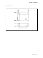
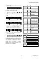
1-4 Controller outline
The outline dimension for the controller are shown in
Fig. 1-1.
Figure 1-1 Controller outline

SECTION II - INSTALLATION
87-900-879-01 (A)4
2-1 General
Inspect the controller for any shipping damage.
The controller is designed to be installed into a rack.
All the connections are fitted to J2, J3, J4 and J5
connectors.
Should the controller be connected to a host computer
via the-RS-232 interface, a suitable cable must be
prepared.
In the following paragraphs are detailed the
input/output signals.
NOTE
The PCB installed into the customer system must be
positioned so that cold air (forced or natural
convection) can flow through the PCB components.
2-2 J2 connector
The signals of J2 connector are the following:
• Pins 1/2 Power supply 24. Vdc (20 to 32 Vdc) (pin
2 positive).
• Pins 4/3 Kl relay contacts. The relay switches when
the output frequency overrides the set threshold
(800 Hz). The threshold overriding is indicated also
on pin 6 of J4 connector.
2-3 J3 connector
The signals of J3 connector are the following:
• Pin 1 42 Vac 3-phase output to pump motor stator
(phase T).
• Pin 2 42 Vac 3-phase output to. pump motor stator
(phase S).
• Pin 3 42 Vac 3-phase output to pump motor stator
(phase R).
• Pins 5/4 Pump temperature sensor.
2-4 J4 connector
The signals of J4 connector are the following:
• Pin 3 Failure. When a fault condition is detected,
the pump is stopped and a signal is present on this
pin.
• Pin 5 Low Speed mode activated. When the Low
Speed mode is activated a signal is present on this
pin.
• Pin 6 When the output frequency is less than 800
Hz, a signal is present on this pin.
• Pin 7 Analog output. A voltage from 0 to 10 Vdc
proportional to the supply current (from 0 to 2.5 A).
• Pin 8 Analog output. A voltage from 0 to 10 Vdc
proportional to the output pump motor driving
frequency (from 0 to 1250 Hz).
• Pin 11 Error reset command. Should an operation
fault be detected (presence of signal on pin 3 of J4),
the pump is stopped. To reset the fault you must
connect pin I I to ground (pin 15 of J4) for at least I
sec.
• Pin 12 ON/OFF pump. To stop the pump you must
connect pin 12 to ground (pin 15 of J4); to start the
pump you must remove the contact between pin 12
and ground.
• Pin 13 Low Speed mode activation. When the
contact between pin 13 and ground (pin 15 of J4)
closes, the turbopump runs at low speed and when
the contact opens, the turbopump reverts to high
speed mode. When the Low Speed mode is
activated an output signal is present on pin 5 of J4.
The Low Speed frequency is 830 Hz.
2-5 J5 RS-232 interface connector
The signal of J5, the RS-232 interface connector, are
the following:
• Pin 1 Ground.
• Pin 2 RXD. Received data.
• Pin 3 TXD. Transmitted data.

SECTION II - INSTALLATION
87-900-879-01 (A)5
2-6 RS-232 communicafion description
Communication format:
• 8 data bit
• no parity
• stop bit
• The baud rate is programmable via a set of jumper
between 4800 and 9600 baud. The controller is
factory-set for 9600 baud operation.
Communication protocol
The communication protocol is of the masterslave type,
where:
• Host = Master
• Eurocard controller = slave
NOTE
To send
a
command by the serial interface, the
controller must be set to "REMOTE OFF” of operation,
otherwise
it is
only possible to read the data.
The master send to the slave a word according to the
following format:
slave
address
where:
• Slave Address: controller number requested by the
master. In RS-232 version the address is set equal
to "001";
• Parameter Number: it points out to the controller
about which parameter the master wants to
operate, and about the kind of operation
(read/write). It consists of:
12345
0=
parameter
reading
1 =
parameter
writing
always 0 000 to 299 = commands
300 to 699 = status
700 to 999 = parameter
• Data Field Lenght: it points out the next field lenght
in characters. In this protocol the possible
combinations are:
02 = parameter reading request
06 = parameter, writing
• Data: in this controller it can be:
“=?”: in the case of parameter reading request
"000000" or "111111": in the case of YES/NO
command or parameter writing
a six numeric character string 0 to 9
pointing out the value of a configuration parameter
or an analogic measure
a six character string pointing out an error
• Checksum: it is the sum of the string ASCII values
up to the first character of the checksum with a 8 bit
cutting-off and a conversion to a decimal number.
• CR: < OxD>
All the fields are set on the right with the "O" character
used as filling character.
When a string with an address number equal to the
card one (001 in this case) is received, the controller
answers as detailed in the following:
• in the case of a parameter request with a string
having the same size described before, but the first
character of the "Parameter Number" field set to 1.
Example for a low speed status request:
Master to Controller:
0010000202= ?097< OxD >
Controller to Master:
0011000206111111016< OxD >
where " 111111" is for low speed status ON
• in the case of a parameter writing, with a string
including the parameter value that has been set out.
Example for a low speed status ON writing:
Master to Controller:
0011000206111111016< OxD >
Controller to Master:
0011000206111111016< OxD >
parameter
number
data
check-
sum
CR
data
field
lenght

SECTION II - INSTALLATION
87-900-879-01 (A)6
• in the case of a string with a lenght greater than 40
characters, with:
NAKCR
Controller address
• in the case of a wrong checksum, with:
NAKCR
Controller address
• in the case of a parameter number not present,
with:
10 06NO-DEF
contoll.
address
param.
address
check-
sum
CR
• in the case of an out-limit value, with:
10 06-RANGE
contoll.
address
param.
address
check-
sum
CR
• in the case of an attempt of writing a logic
parameter with a value not equal to " 000000" or " I
I I I I 1", or when the parameter is a read only one,
with:.
10 06-LOGIC
contoll.
address
param.
address
check-
sum
CR
• in the case of a time between two characters
greater than 1 second, with:
NAKCR
Controller address
Information obtained by the serial interface are listed in
the following table where the column "TYPE" points out
a logic variable with “D” (allowed values "000000" or
"111111") and a numeric variable with "N".
Variables with the first character of "Parameter
Number" equal to X can be either written or read.
Variables with that character equal to “1” can be only
read, equal to "1" can be only written.
PARAMETER
NUMBER
TYPE DESCRIPTION
X0002 D Low speed ON/OFF
X0003 D Pump ON/OFF
X0008 D Remote ON/OFF
10009 D Error acknowledgment:
error status clearing
00302 D K1 status
00303 N Error code: error code
displaying (see the
following table)
00306 D Normal YES/NO
00307 D Starting YES/NO
00309 N Output frequency (Hz)
00310 N Pump current * 100 (A)
00311 N Temperature (°C)
00312 N Software version
The controller sends
"QExxxx" where "xxxx” is
the CRC16 of EPROM
00313 N Power (W)
00314 N Pump life (hours)
00315 N Number of cycles
00316 N Last cycle time (minutes)
00317 N Software version. The
controller sends “Paxxxx”
where "xxxx" is the CRC16
of EEPROM
X0700 N Run up time (minutes)
(read only)
X0701 N Threshold (Hz)
X0702 D Soft-start YES/NO
X0703 D Reduced output power
(YES)
Full output power (NO)
Error Code Table
CODE DESCRIPTION
00E000 No error
OOEOO1 Output current > 15 A
0OE002 Not connected pump
0OE003 Output current > 1.5 A for 15 sec.
0OE004 Bearing temperature > 60 °C
0OE005 Heat exchanger temperature > 60 °C
0OE006 Normal not reached at run up time
0OE007 Input voltage < 16 V for 5 sec.
00EOOS Operating voltage < 10 V for 5 sec.
0OE009 Vp voltage 8V lower than no~ for 5 sec.
OOE010 Soft start ramp not ended within the
expected time

SECTION III - OPERATION
87-900-879-01 (A)7
3-1 General
Make all vacuum manifold and electrical connections
and refer to Turbo-V pump instruction manual prior to
operating the Turbo-V controller.
WARNING
To avoid injury to personnel and damage to the
equipment, if the pump is laying on a table make sure it
is steady.
Never operate the Turbo-V pump if the pump inlet is
not connected to the system or blanked off.
The controller operates completely automatically after
the remote start command is given.
3-2 Switching on/off the pump
To switch on the pump is necessary to remove the
connection between pin 12 of J4 connector and pin 15
(ground) of the same connector.
To switch off the pump is necessary to connect pin 12
of J4 connector to pin IS (ground) of the same
connector.
3-3 Low speed activation/deactivation
To activate the Low Speed status it is necessary to
connect pin 13 of J4 connector to pin 15 (ground) of the
same connector.
To deactivate the Low Speed status it is necessary to
disconnect pin 13 of J4 connector from pin 15 (ground)
of the same connector.
The low speed status is available on pin 5 of the same
connector.
The low speed frequency is equal to 830 Hz.
3-4 Error reset
If the controller identifies an error, the pump is switched
off. After the error cause has been removed, the pump
does not automatically run up. It is necessary to reset
the error status: this is performed connecting pin 11 of
J4 connector to pin 15 (ground) of the same connector
for at least I second.

SECTION IV - MAINTENANCE
87-900-879-01 (A)8
4-1 General
Replacement controllers are available on an advance
exchange basis through Varian. If necessary,
information is provided to aid the operator in
determining malfunctions and corrective steps to be
taken.
WARNING
Voltages developed in the unit are dangerous and may
be fatal. Service must be performed by authorized
personnel only.
4-2 Error messages
For a certain type of failure, the controller will self-
diagnose the error and the following messages will be
displayed.
The controller signals the error occurred by means of a
diagnostic LED located on the board, and on the
RS 232 port.
The LED blinks in a coded mode:
it flashes a number of time equal to the error
code (see the following table) and then stays off, and
so on.
Error Code Table
LED
BLINKING
NUMBER
DESCRIPTION
0 No error
1 Output current> 15 A
2 Not connected pump
3 Output current > 1.5
A for 15 sec.
4 Bearing temperature > 60 °C
5 Heat exchanger temperature
> 60 °C
6 Normal not reached at run up time
7 Input voltage < 16 V for 5 sec.
8 Operating voltage < 10 V for 5 sec.
9 Vp voltage 8V lower than nominal for 5
sec.
10 Soft start ramp not ended within the
expected time
4-3 Accessories and spare parts
DESCRIPTION PART NUMBER
Cable 60 cm long with connector 969-9868

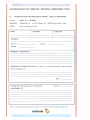
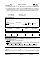
Request for Return
1. A Return Authorization Number (RA#) WILL NOT be issued until this Request for Return is completely filled out,
signed and returned to Varian Customer Service.
2. Return shipments shall be made in compliance with local and international Shipping Regulations (IATA, DOT, UN).
3. The customer is expected to take the following actions to ensure the
Safety
of workers at Varian: (a) Drain any oils or
other liquids, (b) Purge or flush all gasses, (c) Wipe off any excess residues in or on the equipment, (d) Package the
equipment to prevent shipping damage, (for Advance Exchanges please use packing material from replacement unit).
4. Make sure the shipping documents clearly show the RA# and then return the package to the Varian location nearest you.
North and South America
Varian Vacuum Technologies
121 Hartwell Ave
Lexington, MA 02421
Phone : +1 781 8617200
Fax: +1 781 8609252
Europe and Middle East
Varian SpA
Via Flli Varian 54
10040 Leini (TO) – ITALY
Phone: +39 011 9979111
Fax: +39 011 9979330
Asia and ROW
Varian Vacuum Technologies
Local Office
CUSTOMER INFORMATION
Company name: ..………………….……..……………….………………………………..……………………...…………..….
Contact person: Name: ……………………………………..… Tel: ……………………….…...…………….….…....
Fax: …………………………….…...…..…… E-Mail: ..……………………..…………..…..…..…..
Ship Method: …………….……....…… Shipping Collect #: ………….…..………… P.O.#: ………………….…......………..
Europe only: VAT reg. Number: ………………..……………... USA only:
Taxable
Non-taxable
Customer Ship To: ………………………….……… Customer Bill To: …………………..……………...
……………..…………………... ..………………………………...
………………..………………... ..………………………………...
PRODUCT IDENTIFICATION
Product Description Varian P/N Varian S/N Purchase Reference
TYPE OF RETURN (check appropriate box)
Paid Exchange
Paid Repair
Warranty Exchange
Warranty Repair
Loaner Return
Credit
Shipping Error
Evaluation Return
Calibration
Other ……………….
HEALTH and SAFETY CERTIFICATION
Varian Vacuum Technologies CAN NOT ACCEPT any equipment which contains BIOLOGICAL HAZARDS or
RADIOACTIVITY. Call Varian Customer Service to discuss alternatives if this requirement presents a problem.
The equipment listed above (check one):
HAS NOT
been exposed to any toxic or hazardous materials
OR
HAS
been exposed to any toxic or hazardous materials. In case of this selection, check boxes for any materials that
equipment was exposed to, check all categories that apply:
Toxic Corrosive Reactive Flammable Explosive Biological Radioactive
List all toxic or hazardous materials. Include product name, chemical name and chemical symbol or formula.
.……………………………………………………………………………………………………………………..
Print Name: …………………………………. Customer Authorized Signature: ……………...…………………….
Print Title: …………………………………... Date: ..…../..…../……
NOTE:
If a product is received at Varian which is contaminated with a toxic or hazardous material that was not disclosed,
the customer
will be held responsible
for all costs incurred to ensure the safe handling of the product, and
is liable
for any harm or injury to Varian
employees as well as to any third party occurring as a result of exposure to toxic or hazardous materials present in the product.
Do not write below this line
Notification (RA)#: ……………………….……….. Customer ID#: ……….…………. Equipment #: ……………………..

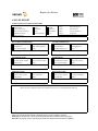
Request for Return
FAILURE REPORT
TURBO PUMPS and TURBOCONTROLLERS
POSITION PARAMETERS
Does not start
Noise
Vertical
Power: Rotational Speed:
Does not spin freely
Vibrations
Horizontal
Current: Inlet Pressure:
Does not reach full speed
Leak
Upside-down
Temp 1: Foreline Pressure:
Mechanical Contact
Overtemperature
Other: Temp 2: Purge flow:
Cooling defective …………………. OPERATION TIME:
TURBOCONTROLLER ERROR MESSAGE:
ION PUMPS/CONTROLLERS VALVES/COMPONENTS
Bad feedthrough
Poor vacuum
Main seal leak
Bellows leak
Vacuum leak
High voltage problem
Solenoid failure
Damaged flange
Error code on display
Other
Damaged sealing area
Other
Customer application:
Customer application:
LEAK DETECTORS INSTRUMENTS
Cannot calibrate
No zero/high backround
Gauge tube not working
Display problem
Vacuum system unstable
Cannot reach test mode
Communication failure
Degas not working
Failed to start
Other
Error code on display
Other
Customer application:
Customer application:
PRIMARY PUMPS DIFFUSION PUMPS
Pump doesn’t start
Noisy pump (describe)
Heater failure
Electrical problem
Doesn’t reach vacuum
Over temperature
Doesn’t reach vacuum
Cooling coil damage
Pump seized
Other
Vacuum leak
Other
Customer application:
Customer application:
FAILURE DESCRIPTION
(Please describe in detail the nature of the malfunction to assist us in performing failure analysis):
NOTA: Su richiesta questo documento è disponibile anche in Tedesco, Italiano e Francese.
REMARQUE : Sur demande ce document est également disponible en allemand, italien et français.
HINWEIS: Auf Aufrage ist diese Unterlage auch auf Deutsch, Italienisch und Französisch erhältlich.

Sales and Service Offices
Argentina
Varian Argentina Ltd.
Sucursal Argentina
Av. Ricardo Balbin 2316
1428 Buenos Aires
Argentina
Tel: (54) 1 783 5306
Fax: (54) 1 786 5172
Australia
Varian Australia Pty Ltd.
679-701 Springvale Road
Mulgrave, Victoria ZZ 3170
Australia
Tel: (61) 395607133
Fax: (61) 395607950
Benelux
Varian Vacuum Technologies
Rijksstraatweg 269 H,
3956 CP Leersum
The Netherlands
Tel: (31) 343 469910
Fax: (31) 343 469961
Brazil
Varian Industria e Comercio Ltda.
Avenida Dr. Cardoso de Mello 1644
Vila Olimpia
Sao Paulo 04548 005
Brazil
Tel: (55) 11 3845 0444
Fax: (55) 11 3845 9350
Canada
Central coordination through:
Varian Vacuum Technologies
121 Hartwell Avenue
Lexington, MA 02421
USA
Tel: (781) 861 7200
Fax: (781) 860 5437
Toll Free: (800) 882 7426
China
Varian Technologies - Beijing
Room 1201, Jinyu Mansion
No. 129A, Xuanwumen Xidajie
Xicheng District
Beijing 1000031 P.R. China
Tel: (86) 10 6608 1530
Fax: (86) 10 6608 1534
France and Wallonie
Varian s.a.
7 avenue des Tropiques
Z.A. de Courtaboeuf – B.P. 12
Les Ulis cedex (Orsay) 91941
France
Tel: (33) 1 69 86 38 13
Fax: (33) 1 69 28 23 08
Germany and Austria
Varian Deutschland GmbH
Alsfelder Strasse 6
Postfach 11 14 35
64289 Darmstadt
Germany
Tel: (49) 6151 703 353
Fax: (49) 6151 703 302
India
Varian India PVT LTD
101-108, 1st Floor
1010 Competent House
7, Nangal Raya Business Centre
New Delhi 110 046
India
Tel: (91) 11 5548444
Fax: (91) 11 5548445
Italy
Varian Vacuum Technologies
Via F.lli Varian, 54
10040 Leini, (Torino)
Italy
Tel: (39) 011 997 9111
Fax: (39) 011 997 9350
Japan
Varian Vacuum Technologies
Sumitomo Shibaura Building, 8th Floor
4-16-36 Shibaura
Minato-ku, Tokyo 108
Japan
Tel: (81) 3 5232 1253
Fax: (81) 3 5232 1263
Korea
Varian Technologies Korea, Ltd.
Shinsa 2nd Bldg. 2F
966-5 Daechi-dong
Kangnam-gu, Seoul
Korea 135-280
Tel: (82) 2 3452 2452
Fax: (82) 2 3452 2451
Mexico
Varian S.A.
Concepcion Beistegui No 109
Col Del Valle
C.P. 03100
Mexico, D.F.
Tel: (52) 5 523 9465
Fax: (52) 5 523 9472
Ta i w a n
Varian Technologies Asia Ltd.
18F-13 No.79, Hsin Tai Wu Road
Sec. 1, Hsi Chih
Taipei Hsien
Taiwan, R.O.C.
Tel: (886) 2 2698 9555
Fax: (886) 2 2698 9678
UK and Ireland
Varian Ltd.
28 Manor Road
Walton-On-Thames
Surrey KT 12 2QF
England
Tel: (44) 1932 89 8000
Fax: (44) 1932 22 8769
United States
Varian Vacuum Technologies
121 Hartwell Avenue
Lexington, MA 02421
USA
Tel: (781) 861 7200
Fax: (781) 860 5437
Toll Free: (800) 882 7426
Other Countries
Varian Vacuum Technologies
Via F.lli Varian, 54
10040 Leini, (Torino)
Italy
Tel: (39) 011 997 9111
Fax: (39) 011 997 9350
Internet Users:
Customer Service & Technical Support:
vtt.customer.service@varianinc.com
Worldwide Web Site:
www.varianinc.com/vacuum
Order On-line:
www.evarian.com
Representatives in most countries
11/01
-
 1
1
-
 2
2
-
 3
3
-
 4
4
-
 5
5
-
 6
6
-
 7
7
-
 8
8
-
 9
9
-
 10
10
-
 11
11
-
 12
12
-
 13
13
-
 14
14
-
 15
15


Varian Turbo-V70 Instructions Manual
- Tipo
- Instructions Manual
- Questo manuale è adatto anche per
in altre lingue
- English: Varian Turbo-V70
Documenti correlati
-
Varian Turbo-V 81 969-9538 Manuale utente
-
-
-
-
-
-
-
-
-
