
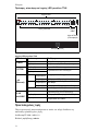
Gigabit Smart Switch
Quick Installation Guide
Guida per l'installazione rapida
Hõ zlõ Kurulum Kõ lavuzu
Οδηγός γρήγορης εγκατάστασης
R24.0720.00
rev 3.3 05/07

2

1
Contents
English . . . . . . . . . . . . . . . . . . . . . . . . . . . . . . . . . . . . . . 1
Introduction ............................................................................1
Installation ............................................................................ 5
Troubleshooting...................................................................... 9
Additional Information ............................................................10
Italiano . . . . . . . . . . . . . . . . . . . . . . . . . . . . . . . . . . . . . .11
Introduzione .......................................................................... 11
Installazione .........................................................................15
Risoluzione di problemi ..........................................................19
Informazioni aggiuntive ......................................................... 20
Türkçe . . . . . . . . . . . . . . . . . . . . . . . . . . . . . . . . . . 21
Giriş ................................................................................. 21
Kurulum ............................................................................ 25
Sorun Giderme ................................................................... 29
Ek Bilgiler ......................................................................... 30
Ελληνικά . . . . . . . . . . . . . . . . . . . . . . . . . . . . . . . . . 31
Εισαγωγή .......................................................................... 31
Εγκατάσταση ..................................................................... 35
Αντιμετώπιση προβλημάτων ................................................ 39
Πρόσθετες πληροφορίες ...................................................... 40
Support / Servizio assistenza / Destek / Υποστήριξη . . 41

2

English
1
English
Introduction
This guide covers installation of the following Gigabit Smart Switch models:
! 7624
A—24-Port 10/100 PoE + 4-Port Gigabit Smart Switch
! 7716
A—10/100/1000 Mbps 16-Port Smart Switch
! 7724
A—10/100/1000 Mbps 24-Port Smart Switch
! 7748—10/100/1000 Mbps 48-Port Smart Switch
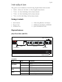
Package Contents
Physical Features
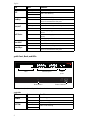
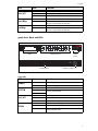
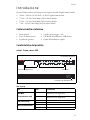
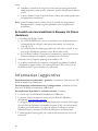
7624A Front, Back, and LEDs
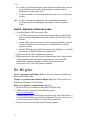
Model 7624A. 24-Port 10/100 PoE + 4-Port Gigabit Smart Switch.
7624
A LEDs
! Smart Switch ! 2 Mounting Brackets and Screws
! Power Cord ! USRobotics Installation CD-ROM
! 4 Rubber Feet ! Quick Installation Guide
LED State Condition
PWR MAX
On Not enough power for additional PoE-powered
device
Off Enough power for additional PoE-powered
device
FAN
OK Fan is working
Fail Fan is not working
PWR
On Receiving power
Off Not receiving power
AC IN
LEDs PoE ports
Power connector
1 3 5 7
PWR
SYS
Fail
FAN
PWR MAX
OK
1 3 5 7 9 11 13 15 1 7 19 21 23
2 4 6 8 10 12 14 1 6 18 20 22 24 25 26 27 2 8
1000BASE-T
100Mbps
Link/ACT
PoE Status
100Mbps
Link/ACT
PoE Status
1000Mbps
Link/ACT
100Mbps
mini-GBIC
2 4 6 8
9 11 13 15
10 12 14 1 6
17 19 21 2 3
18 20 22 2 4
RESET
24-Port 10/100 PoE
+ 4-Port Gigabit Smart Switch
26 26 28
25 27
25 mini-GBIC
Reset button
Gigabit Ethernet ports
GBIC ports

2
English
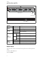
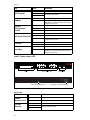
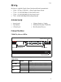
7716A Front, Back, and LEDs
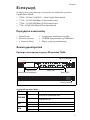
Model 7716A. 10/100/1000 Mbps 16-Port Smart Switch.
7716
A LEDs
SYS
Blinking CPU is working
On
CPU is not working
Off
100Mbps
On Link rate is 100 Mbps
Off Link rate is 10 Mbps or 1000 Mbps, or no active
device is connected to the port
Link/ACT
On Link is up
Blinking Port is transmitting or receiving data
Off Link is down
PoE Status
Green Port is supplying power to the connected
device
Red Port cannot supply power to the connected
device
Off No PoE-compatible device is connected
mini-GBIC
On Mini-GBIC connection is active
Off Mini-GBIC connection is not active
1000 Mbps
On Link rate is 1000 Mbps
Off Link rate is 10 Mbps or 100 Mbps, or no active
device is connected to the port
LED State Condition
POWER
On Receiving power
Off Not receiving power
SYSTEM
Blinking CPU is working
On
CPU is not working
Off
LED State Condition
RESET
AC LINE
100-240VAC
50-60 Hz,1.2A
1
53
7
13 159
11
264 8 14 1610 12
POWER
SYSTEM
Link/ACT
1000Mbps
100Mbps
1000Mbps
Link / ACT
12
3
4
56
7
89
10
11 12
13
14
15 1516 16
15 16
mini-GBIC
mini-GBIC
10/100/1000 Mbps
16-Port Smart Switch
LEDs Ethernet ports GBIC
ports
Reset button Power connector

English
3
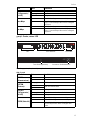
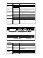
7724A Front, Back, and LEDs
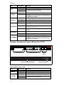
Model 7724A. 10/100/1000 Mbps 24-Port Smart Switch.
7724
A LEDs
Link/ACT
On Link is up
Blinking Port is transmitting or receiving data
Off Link is down
1000 Mbps
On Link rate is 1000 Mbps
Off Link rate is 10 Mbps or 100 Mbps, or no active
device is connected to the port
100Mbps
On Link rate is 100 Mbps
Off Link rate is 10 Mbps or 1000 Mbps, or no active
device is connected to the port
LED State Condition
POWER
On Receiving power
Off Not receiving power
SYSTEM
Blinking CPU is working
On
CPU is not working
Off
Link/ACT
On Link is up
Blinking Port is transmitting or receiving data
Off Link is down
SPEED
Amber Link rate is 100 Mbps
Green Link rate is 1000 Mbps
Off Link rate is 10 Mbps or no active device is con-
nected to the port
LED State Condition
LEDs Ethernet ports GBIC
ports
Reset button Power connector
SPEED
Link/ACT
POWER
SYSTEM
SPEED
Link / ACT
23
24
mini-GBIC
1357
2468
9111315 17192123
10 12 14 16 18 20 22 24
23 24
mini-GBIC
10/100/1000 Mbps
24-Port Smart Switch
24
6 8 10
12 14
16 18 20
22 24
13
5 7 9
11 13
15 17 19
21 23
RESET
AC LINE
100-240VAC
50-60 Hz,1.2A

4
English
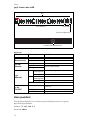
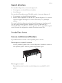
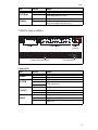
7748 Front, Back, and LEDs
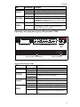
Model 7748. 10/100/1000 Mbps 48-Port Smart Switch.
7748 LEDs
Default Values
All of the smart switches documented in this guide have the following default
values:
IP address:
192.168.0.1
Password: admin
LED State Condition
POWER
On Receiving power
Off Not receiving power
SYSTEM
Blinking CPU is working
On
CPU is not working
Off
1–48
(Ethernet)
Green Solid or
blinking
Link rate is 1000 Mbps
Blinking Port is transmitting or receiving data
Amber Solid or
blinking
Link rate is 10 Mbps or 100 Mbps
Blinking Port is transmitting or receiving data
Off Link is down
45–48
mini-GBIC
On Mini-GBIC module is installed and connected
Blinking Port is transmitting or receiving data
Off No mini-GBIC module is installed
10/100/1000 Mbps
48-Port Smart Switch
LEDs
Ethernet ports
GBIC
ports
Reset button
Power connector
AC LINE 100-240 VAC
50-60Hz 1.4A

English
5
System Requirements
To install the switch, you need the following:
! A computer with an Ethernet adapter installed
! An Ethernet cable
For access to the switch’s Web User Interface, you need the following:
! A computer with an Ethernet adapter installed
! An HTML 4.01-compliant Web Browser (such as Internet Explorer 5.5 or
later or Netscape 8.0 or later) with JavaScript enabled
To use the Smart Switch Configuration Utility, the computer must be running
one of the following operating systems: Windows Vista™, Windows® XP, or
Windows® 2000. If you are not using one of these operating systems, you can
perform all configuration functions through the Web User Interface.
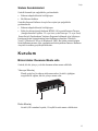
Installation
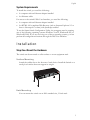
Step One: Mount the Hardware
The switch can be mounted on a flat surface or on an equipment rack.
Surface Mounting
Attach the rubber feet to the bottom of each device. Install the Switch on a
sturdy, level surface that can support its weight.
Rack Mounting
You can mount the switch on an EIA standard-size, 19-inch rack.

6
English
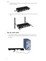
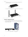
1. Attach a bracket to each side of the switch, and secure the brackets with
the provided screws:
2. Use screws provided with the equipment rack to mount the switch in the
rack.:
Step Two: Attach Cables
1. Use an Ethernet cable to connect any Ethernet port on the switch to the
Ethernet port on a computer. The computer will be used to set the switch’s
IP address.
1
53
7
13 159
11
264 8 14 1610 12
POWER
SYSTEM
Link/ACT
1000Mbps
100Mbps
1000Mbps
Link / ACT
12
3
4
56
7
89
10
11 12
13
14
15 1516 16
15 16
mini-GBIC
mini-GBIC
10/100/1000 Mbps
16-Port Smart Switch

English
7
2. Connect the power cord to the 100-240VAC port on the switch, then plug
the power cord into a standard power outlet.
Step Three: Assign an IP Address to the Switch
If you are using an operating system other than Windows, see the User Guide on
the USRobotics Installation CD-ROM for instructions on assigning an IP
address to the switch.
If you are using a Windows operating system, the Smart Switch Configuration
Utility is the easiest way to set up the switch’s basic configuration. For informa-
tion about other features available in the utility, see the User Guide on the
USRobotics Installation CD-ROM.
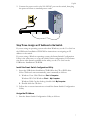
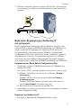
Install the Smart Switch Configuration Utility
1. Insert the USRobotics Installation CD-ROM in the CD or DVD drive.
If the CD doesn’t start automatically, start it manually as follows:
A. Windows Vista: Click Windows
Start > Computer.
Windows XP: Click Windows Start > My Computer.
Windows 2000: On the desktop, double-click
My Computer.
B. Double-click the CD drive.
2. Follow the on-screen instructions to install the Smart Switch Configuration
Utility.
Assign the IP Address
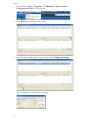
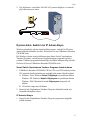
1. Start the Smart Switch Configuration Utility as follows:
1
53
7
13 159
11
264 8 14 1610 12
POWER
SYSTEM
Link/ACT
1000Mbps
100Mbps
1000Mbps
Link / ACT
12
3
4
56
7
89
10
11 12
13
14
15 1516 16
15 16
mini-GBIC
mini-GBIC
10/100/1000 Mbps
16-Port Smart Switch

8
English
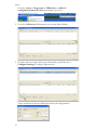
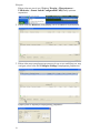
Click Windows Start > Programs > USRobotics > Smart Switch
Configuration Utility as shown below:
2. Click Discover to find the smart switch.
3. Click the smart switch entry to select it; then click Configure Settings:
The Configuration setting window appears:

English
9
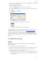
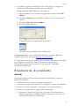
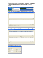
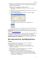
4. You can assign a static IP address to the switch or configure the switch to get
its address from a DHCP server.
Setting a Static IP Address:
A. Enter the IP Address that you want the switch to have.
B. Enter the Gateway address of the network to which you will connect the
switch.
C. In Password, enter
admin.
D. Click Set:
The utility confirms the configuration of the switch:
The switch is now accessible at its new IP address.
Congratulations. You have successfully completed the installation proce-
dure. Please register your Gigabit Smart Switch at
www.usr.com/productreg/
.
You can now connect the switch to the network and access its Web User
Interface to configure other features of the switch. For more information about
using the Web User Interface, see the User Guide on the USRobotics Installation
CD-ROM.
Troubleshooting
General
This procedure addresses a number of symptoms that you might experience
during installation:
1. Verify that all cables are connected properly.
2. Ensure that the power outlet to which the switch is connected is a live outlet.
3. Restart the switch by removing and then reconnecting its power cable.
4. Consider the following environmental factors:
A. Install the switch in a cool and dry place. For acceptable temperature and
humidity operating ranges, see the User Guide on the USRobotics Installa-
tion CD-ROM.

10
English
B. Install the switch in a site free from strong electromagnetic field genera-
tors (such as motors), vibration, dust, and direct exposure to sunlight.
C. Leave at least 10cm of space at the front and rear of the switch for venti-
lation.
Note:If you decide to reset the switch, record the configuration settings first.
Resetting the switch causes all values to revert to their factory settings.
If the switch does not appear in the Discovery List:
1. Check the LEDs on the switch:
" If the Power LED is not on, check the power cable and ensure that it is
connected to a live outlet. The switch uses 100-240 Volts AC.
" If the System LED is not blinking, try rebooting the switch. If rebooting
does not solve the problem, press the Reset button on the switch.
" If no LED indicates link or activity for the Ethernet port connected to
the computer, check your Ethernet cable.
2. Make sure your computer has an IP address.
3. If you are using a firewall on your computer, configure it to allow the Smart
Switch Configuration Utility. The utility uses UDP packets with destination
port 64515 to communicate with the switches.
Additional Information
For regulatory and warranty information, see the User Guide on the
USRobotics Installation CD-ROM.
For operation and configuration information, see the User Guide on the
USRobotics Installation CD-ROM.
For additional troubleshooting and technical support, see:
1. The User Guide on the USRobotics Installation CD-ROM.
2. The Support section of the USRobotics Web site at
www.usr.com/support/
.
Many of the most common difficulties that users experience have been
addressed in the FAQ and Troubleshooting Web pages for your Smart
Switch. The Support pages also contain current support contact information
and documentation.
3. The support contact information on the last page of this guide.

Italiano
11
Italiano
Introduzione
Questa Guida contiene informazioni sui seguenti modelli Gigabit Smart Switch:
! 7624
A—24-Port 10/100 PoE + 4-Port Gigabit Smart Switch
! 7716
A—10/100/1000 Mbps 16-Port Smart Switch
! 7724
A—10/100/1000 Mbps 24-Port Smart Switch
! 7748
—10/100/1000 Mbps 48-Port Smart Switch
Contenuto della confezione
Caratteristiche del prodotto
7624A - Fronte, retro e LED
Modello 7624A. 24-Port 10/100 PoE + 4-Port Gigabit Smart Switch.
LED di 7624
A
! Smart Switch ! 2 staffe di montaggio e viti
! Cavo di alimentazione ! CD-ROM di installazione USRobotics
! 4 piedini di gomma ! Guida all'installazione rapida
LED Stato Condizione
PWR MAX
(Alimentazione max)
Acceso Alimentazione non sufficiente per
dispositivo PoE aggiuntivo
Spento Alimentazione sufficiente per
dispositivo PoE aggiuntivo
FAN (Ventilatore)
OK Ventilatore funzionante
Fail (Errore) Ventilatore non funzionante
PWR (Alimentazione)
Acceso Alimentato
Spento Non alimentato
AC IN
LED Porte PoE
Connettore di alimentazione
1 3 5 7
PWR
SYS
Fail
FAN
PWR MAX
OK
1 3 5 7 9 11 13 15 1 7 19 21 23
2 4 6 8 10 12 14 1 6 18 20 22 24 25 26 27 28
1000BASE-T
100Mbps
Link/ACT
PoE Status
100Mbps
Link/ACT
PoE Status
1000Mbps
Link/ACT
100Mbps
mini-GBIC
2 4 6 8
9 11 13 15
10 12 14 1 6
17 19 21 2 3
18 20 22 2 4
RESET
24-Port 10/100 PoE
+ 4-Port Gigabit Smart Switch
26 26 28
25 27
25 mini-GBIC
Tasto Reset (Ripristino)
Porte Ethernet Gigabit
Porte GBIC

12
Italiano
7716A - Fronte, retro e LED
Modello 7716A. 10/100/1000 Mbps 16-Port Smart Switch.
LED di 7716
A
SYS (Sistema)
Lampeggiante CPU funzionante
Acceso
CPU non funzionante
Spento
100Mbps
Acceso Velocità di collegamento: 100 Mbps
Spento Velocità di collegamento di 10 Mbps o
1000 Mbps, o nessun dispositivo attivo
collegato alla porta
Link/ACT
(Collegamento/
attività)
Acceso Collegamento attivato
Lampeggiante Trasmissione o ricezione di dati in corso
Spento Collegamento non attivato
PoE Status (Stato PoE)
Verde Dispositivo connesso alimentato
Rosso Dispositivo connesso non alimentato
Spento Non è connesso alcun dispositivo
compatibile con PoE
mini-GBIC
Acceso Connessione Mini-GBIC attiva
Spento Connessione Mini-GBIC non attiva
1000 Mbps
Acceso Velocità di collegamento: 1000 Mbps
Spento Velocità di collegamento di 10 Mbps o
100 Mbps, o nessun dispositivo attivo
collegato alla porta
LED Stato Condizione
POWER
(Alimentazione)
Acceso Alimentato
Spento Non alimentato
SYSTEM
(Sistema)
Lampeggiante CPU funzionante
Acceso
CPU non funzionante
Spento
LED Stato Condizione
RESET
AC LINE
100-240VAC
50-60 Hz,1.2A
1
53
7
13 159
11
264 8 14 1610 12
POWER
SYSTEM
Link/ACT
1000Mbps
100Mbps
1000Mbps
Link / ACT
12
3
4
56
7
89
10
11 12
13
14
15 1516 16
15 16
mini-GBIC
mini-GBIC
10/100/1000 Mbps
16-Port Smart Switch
LED Porte Ethernet Porte GBIC
Tasto Reset (Ripristino) Connettore di alimentazione

Italiano
13
7724A - Fronte, retro e LED
Modello 7724A. 10/100/1000 Mbps 24-Port Smart Switch.
LED di 7724
A
Link/ACT
(Collegamento/
attività)
Acceso Collegamento attivato
Lampeggiante Trasmissione o ricezione di dati in corso
Spento Collegamento non attivato
1000 Mbps
Acceso Velocità di collegamento: 1000 Mbps
Spento Velocità di collegamento di 10 Mbps o 100
Mbps, o nessun dispositivo attivo collegato
alla porta
100 Mbps
Acceso Velocità di collegamento: 100 Mbps
Spento Velocità di collegamento di 10 Mbps o 1000
Mbps, o nessun dispositivo attivo collegato
alla porta
LED Stato Condizione
POWER
(Alimentazione)
Acceso Alimentato
Spento Non alimentato
SYSTEM
(Sistema)
Lampeggiante CPU funzionante
Acceso
CPU non funzionante
Spento
Link/ACT
(Collegamento/
attività)
Acceso Collegamento attivato
Lampeggiante Trasmissione o ricezione di dati in corso
Spento Collegamento non attivato
SPEED (Velocità)
Ambra Velocità di collegamento: 100 Mbps
Verde Velocità di collegamento: 1000 Mbps
Spento Velocità di collegamento di 10 Mbps, o
nessun dispositivo attivo collegato alla
porta
LED Stato Condizione
LED Porte Ethernet Porte GBIC
Tasto Reset (Ripristino) Connettore di alimentazione
SPEED
Link/ACT
POWER
SYSTEM
SPEED
Link / ACT
23
24
mini-GBIC
1357
2468
9111315 17192123
10 12 14 16 18 20 22 24
23 24
mini-GBIC
10/100/1000 Mbps
24-Port Smart Switch
24
6 8 10
12 14
16 18 20
22 24
13
5 7 9
11 13
15 17 19
21 23
RESET
AC LINE
100-240VAC
50-60 Hz,1.2A

14
Italiano
7748 - Fronte, retro e LED
Modello 7748. 10/100/1000 Mbps 48-Port Smart Switch.
LED di 7748
Valori predefiniti
Tutti gli Smart Switch a cui si riferisce questa Guida presentano le seguenti
impostazioni predefinite:
Indirizzo IP:
192.168.0.1
Password: admin
LED Stato Condizione
POWER
(Alimentazione)
Acceso Alimentato
Spento Non alimentato
SYSTEM
(Sistema)
Lampeggiante CPU funzionante
Acceso
CPU non funzionante
Spento
1–48
(Ethernet)
Verde Acceso o
lampeggiante
Velocità di collegamento: 1000 Mbps
Lampeggiante Trasmissione o ricezione di dati in corso
Ambra Acceso o
lampeggiante
Velocità di collegamento: 10 o 100 Mbps
Lampeggiante Trasmissione o ricezione di dati in corso
Spento Collegamento non attivato
45–48
mini-GBIC
Acceso Il modulo Mini-GBIC è installato e
connesso
Lampeggiante Trasmissione o ricezione di dati in corso
Spento Non è installato alcun modulo Mini-GBIC
10/100/1000 Mbps
48-Port Smart Switch
LED
Porte Ethernet
Porte GBIC
Tasto Reset (Ripristino)
Connettore di alimentazione
AC LINE 100-240 VAC
50-60Hz 1.4A

Italiano
15
Requisiti del sistema
Per installare il dispositivo, è necessario disporre di:
! Un computer con scheda Ethernet installata
! Cavo Ethernet
Per accedere all'interfaccia utente Web dello switch, è necessario disporre di:
! Un computer con scheda Ethernet installata
! Browser Web compatibile con HTML 4.01 (Internet Explorer 5.5 o versione
successiva oppure Netscape 8.0 o versione successiva) e con JavaScript
abilitato
Per usare l'utilità di configurazione Smart Switch, il computer deve disporre di
uno dei seguenti sistemi operativi: Windows Vista™, Windows® XP o
Windows® 2000. Se si utilizza un sistema operativo diverso, è possibile eseguire
tutte le funzioni di configurazione tramite l'interfaccia utente Web.
Installazione
Fase uno: installazione dell'hardware
È possibile montare lo switch su una superficie piana o un rack.
Montaggio su superficie piana
Fissare i piedini di gomma sotto a ciascun dispositivo. Installare lo switch su
una superficie piana e solida, in grado di supportarne il peso.
Montaggio su rack
È possibile montare lo switch su rack di dimensioni standard EIA di 19
pollici.

16
Italiano
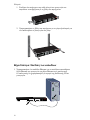
1. Posizionare una staffa su ciascun lato dello switch e fissarla con le viti
fornite in dotazione:
2. Usare le viti fornite in dotazione con il rack per fissare lo switch nel rack:
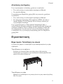
Fase due: collegamento dei cavi
1. Usare un cavo Ethernet per collegare una porta Ethernet dello switch alla
porta Ethernet del computer. È necessario usare il computer per impostare
l'indirizzo IP dello switch.
1
53
7
13 159
11
264 8 14 1610 12
POWER
SYSTEM
Link/ACT
1000Mbps
100Mbps
1000Mbps
Link / ACT
12
3
4
56
7
89
10
11 12
13
14
15 1516 16
15 16
mini-GBIC
mini-GBIC
10/100/1000 Mbps
16-Port Smart Switch
La pagina si sta caricando...
La pagina si sta caricando...
La pagina si sta caricando...
La pagina si sta caricando...
La pagina si sta caricando...
La pagina si sta caricando...
La pagina si sta caricando...
La pagina si sta caricando...
La pagina si sta caricando...
La pagina si sta caricando...
La pagina si sta caricando...
La pagina si sta caricando...
La pagina si sta caricando...
La pagina si sta caricando...
La pagina si sta caricando...
La pagina si sta caricando...
La pagina si sta caricando...
La pagina si sta caricando...
La pagina si sta caricando...
La pagina si sta caricando...
La pagina si sta caricando...
La pagina si sta caricando...
La pagina si sta caricando...
La pagina si sta caricando...
La pagina si sta caricando...
La pagina si sta caricando...
La pagina si sta caricando...
La pagina si sta caricando...
-
 1
1
-
 2
2
-
 3
3
-
 4
4
-
 5
5
-
 6
6
-
 7
7
-
 8
8
-
 9
9
-
 10
10
-
 11
11
-
 12
12
-
 13
13
-
 14
14
-
 15
15
-
 16
16
-
 17
17
-
 18
18
-
 19
19
-
 20
20
-
 21
21
-
 22
22
-
 23
23
-
 24
24
-
 25
25
-
 26
26
-
 27
27
-
 28
28
-
 29
29
-
 30
30
-
 31
31
-
 32
32
-
 33
33
-
 34
34
-
 35
35
-
 36
36
-
 37
37
-
 38
38
-
 39
39
-
 40
40
-
 41
41
-
 42
42
-
 43
43
-
 44
44
-
 45
45
-
 46
46
-
 47
47
-
 48
48


US Robotics 7624A Quick Installation Manual
- Tipo
- Quick Installation Manual
- Questo manuale è adatto anche per
Altri documenti
-
D-Link Food Warmer DES-1526 Manuale utente
-
Trendnet RB-TL2-G244 Scheda dati
-
-
Trendnet TEG-160WS Scheda dati
-
Trendnet RB-TEG-424WS Scheda dati
-
Nortel 2361 Manuale utente
-
Trendnet TEG-2248WS Scheda dati
-
-
-
Cisco 7606 Guida d'installazione