Mode AVIC F9310 BT Manuale del proprietario
- Categoria
- Microfoni
- Tipo
- Manuale del proprietario
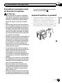
Questo manuale è adatto anche per

Installation Manual
Manuel d’installation
NAVIGATION AV SYSTEM
SYSTEME DE NAVIGATION AV
SISTEMA DI NAVIGAZIONE AV
SISTEMA DE NAVEGACIÓN AV
NAVIGATIONS-/AV-SYSTEM
AV NAVIGATIESYSTEEM
AVIC-F9310BT
Some wiring and installation are described in the
separate installation manual.
Certains câblages et procédés d’installation sont décrits
dans le manuel d’installation séparé.
Alcuni dati di cablaggio e installazione sono descritti nel
Manuale d’installazione separato.
En el manual de instalación independiente se describe
parte del proceso de cableado e instalación.
Gewisse Verkabelungs- und Installationsarbeiten sind in
der separaten Einbauanleitung beschrieben.
Sommige bedradings- en installatie-informatie staat in
de afzonderlijke installatiehandleiding.
English NederlandsDeutschEspañolItalianoFrançais

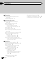
Precautions
Your new navigation system and this
manual 3
Important safeguards 3
Connecting the system
Precautions before connecting the
system 4
Before installing this product 4
To prevent damage 5
– Notice for the blue lead 5
– Notice for the violet/white lead 5
Parts supplied 6
Connecting the system 8
When connecting to separately sold power
amp 10
When connecting a rear view camera 12
When connecting the external video
component 13
– Using an AV input (AV1) 13
– Using an AV input (AV2) 14
When connecting the rear display 14
– When using a rear display connected to
rear video output 14
Installation
Precautions before installation 15
To avoid electromagnetic interference 15
Before installing 15
Installing the navigation system 16
– Installation notes 16
Concealing the metal brackets 17
Installing the GPS aerial 18
– Installation notes 18
– Parts supplied 18
– When installing the aerial inside the
vehicle (on the dashboard or rear
shelf) 19
Installing the microphone 20
– Parts supplied 20
– Mounting on the sun visor 20
– Installation on the steering column 21
– Adjusting the microphone angle 21
Contents
Engb
2

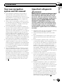
Your new navigation
system and this manual
! The navigation features of this product
(and the rear view camera option if pur-
chased) are intended solely to aid you in
the operation of your vehicle. It is not a sub-
stitute for your attentiveness, judgement
and care when driving.
! Never use this navigation system to route
to hospitals, police stations, or similar facil-
ities in an emergency. Please call the ap-
propriate emergency number.
! Do not operate this navigation system (or
the rear view camera option if purchased) if
doing so will divert your attention in any
way from the safe operation of your vehicle.
Always observe safe driving rules and fol-
low all existing traffic regulations. If you ex-
perience difficulty in operating the system
or reading the display, park your vehicle in
a safe location and apply the handbrake be-
fore making the necessary adjustments.
! This manual explains how to install this na-
vigation system in your vehicle. However,
some wiring and installation are described
in the separate installation manual. Opera-
tion of this navigation system is explained
in a separate manual.
! Do not install this product where it may (i)
obstruct the driver’s vision, (ii) impair the
performance of any of the vehicle’s operat-
ing systems of safety features, including
airbags, hazard lamp buttons, or (iii) impair
the driver’s ability to safely operate the vehi-
cle. In some cases, it may not be possible
to install this product because of the vehi-
cle type or the shape of the vehicle inter-
ior.
Important safeguards
WARNING
Pioneer does not recommend that you install
your navigation system yourself. We recom-
mend that only authorised Pioneer service
personnel, who have special training and ex-
perience in mobile electronics, set up and in-
stall this product. NEVER SERVICE THIS
PRODUCT YOURSELF. Installing or servi-
cing this product and its connecting cables
may expose you to the risk of electric shock
or other hazards, and can cause damage to
the navigation system that is not covered by
warranty.
! Read this manual fully and carefully before
installing your navigation system.
! Keep this manual handy for future refer-
ence.
! Pay close attention to all warnings in this
manual and follow the instructions care-
fully.
! This navigation system may in certain cir-
cumstances display inaccurate position of
your vehicle, the distance of objects shown
on the screen, and compass directions. In
addition, the system has certain limita-
tions, including the inability to identify one-
way streets, temporary traffic restrictions
and potentially unsafe driving areas. Please
exercise your own judgement in the light of
actual driving conditions.
! As with any accessory in your vehicle’s in-
terior, the navigation system should not di-
vert your attention from the safe operation
of your vehicle. If you experience difficulty
in operating the system or reading the dis-
play, please make adjustments while safely
parked.
! Please remember to wear your seat belt at
all times while operating your vehicle. If
you are in an accident, your injuries can be
considerably more severe if your seat belt
is not properly fastened.
! Certain country and government laws may
prohibit or restrict the placement and use
of this system in your vehicle. Please com-
ply with all applicable laws and regulations
regarding the use, installation and opera-
tion of your navigation system.
Engb
3
English
Section
01
Precautions

Precautions before
connecting the system
CAUTION
! If you decide to perform the installation
yourself, and have special training and ex-
perience in the mobile electronics instal-
lations, please carefully follow all of the
steps in the installation manual.
! Secure all wiring with cable clamps or
electrical tape. Do not allow any bare wir-
ing to remain exposed.
! It is extremely dangerous to allow cables
to become wound around the steering col-
umn or gearstick. Be sure to install this
product, its cables, and wiring away in
such so that they will not obstruct or hin-
der driving.
! Make sure that the cables and wires will
not interfere with or become caught in
any of the vehicle’s moving parts, espe-
cially the steering wheel, gearstick, hand-
brake, sliding seat tracks, doors, or any of
the vehicle’s controls.
! Do not route wires where they will be ex-
posed to high temperatures. If the insula-
tion heats up, wires may become
damaged, resulting in a short circuit or
malfunction and permanent damage to
the product.
! Do not cut the GPS aerial cable to shorten
it or use an extension to make it longer.
Altering the aerial cable could result in a
short circuit or malfunction.
! Do not shorten any leads. If you do, the
protection circuit (fuse holder, fuse resis-
tor or filter, etc.) may fail to work properly.
! Never feed power to other electronic pro-
ducts by cutting the insulation of the
power supply lead of the navigation sys-
tem and tapping into the lead. The current
capacity of the lead will be exceeded,
causing overheating.
Before installing this product
! Use this unit with a 12-volt battery and ne-
gative earthing only. Failure to do so may
result in a fire or malfunction.
! To avoid shorts in the electrical system, be
sure to disconnect the (–) battery cable be-
fore installation.
Engb
4
Section
02
Connecting the system

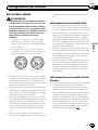
To prevent damage
WARNING
! Use speakers over 50 W (output value)
and between 4 W to 8 W (impedance value).
Do not use 1 W to 3 W speakers for this
unit.
! When replacing the fuse, be sure to only
use a fuse of the rating prescribed on this
product.
! When disconnecting a connector, pull the
connector itself. Do not pull the lead, as
you may pull it out of the connector.
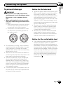
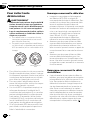
! This product cannot be installed in a vehi-
cle without ACC (accessory) position on
the ignition switch.
A
C
C
O
N
S
T
A
R
T
O
F
F
O
N
S
T
A
R
T
O
F
F
ACC position No ACC position
! To avoid short-circuiting, cover the discon-
nected lead with insulating tape. It is espe-
cially important to insulate all unused
speaker leads, which if left uncovered may
cause a short circuit.
! Refer to the owner’s manual for details on
connecting the power amp and other units,
then make connections accordingly.
! Since a unique BPTL circuit is employed,
do not directly earth the * side of the
speaker lead or connect the * side of an-
other side of the speaker lead together. Be
sure to connect the * side of the speaker
lead to the * side of the speaker lead on
this navigation system.
! If the RCA pin jack on this product will not
be used, do not remove the caps attached
to the end of the connector.
Notice for the blue lead
! When the ignition switch is turned on (ACC
ON), a control signal is output through the
blue lead. Connect to an external power
amp’s system remote control terminal, the
auto-aerial relay control terminal, or the
aerial booster power control terminal (max.
300 mA 12 V DC). The control signal is out-
put through the blue lead, even if the audio
source is switched off.
! Be sure not to use this lead as the power
supply lead for the external power amps.
Such connection could cause excessive
current drain and malfunction.
! Be sure not to use this lead as the power
supply lead for the auto-aerial or aerial
booster. Such connection could cause ex-
cessive current drain and malfunction.
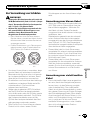
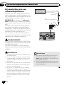
Notice for the violet/white lead
! The violet/white lead must be connected so
that the navigation system can detect
whether the vehicle is moving forwards or
backwards. Connect the violet/white lead to
the lead whose voltage changes when the
reverse gear is engaged. Unless connected,
the sensor may not detect your vehicle tra-
velling forwards/backwards properly, and
thus your vehicle position as detected by
the sensor may not correspond to the ac-
tual position.
Engb
5
English
Section
02
Connecting the system

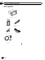
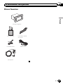
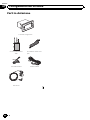
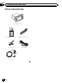
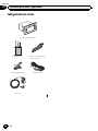
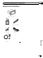
Parts supplied
The navigation unit
RDS-TMC tuner USB and mini-jack
connector
RCA connector GPS aerial
Microphone
Engb
6
Section
02
Connecting the system

Engb
7
English
Section
02
Connecting the system

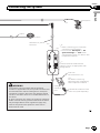
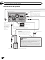
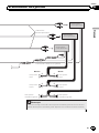
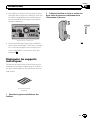
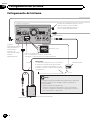
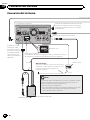
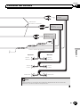
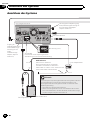
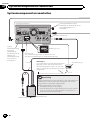
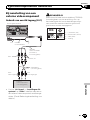
Connecting the system
The navigation unit
Wired remote input
Please refer to the
instruction manual
for the Wired Remote
Control Adapters
(sold separately).
Vehicle Bus adapter input
Please refer to the instruction
manual for the Vehicle Bus
adapter (sold separately).
Power cord
For connection, refer to the wiring and
installation manual separately supplied.
Audio source will be set to mute or attenuate, while the
following sounds will not be muted or attenuated. For details,
refer to Operation Manual.
— voice guidance of the navigation
— incoming ringtone and incoming voice of the mobile
phone that is connected to this navigation system via
Bluetooth wireless technology
15 cm
Note
RCA connector
Yellow/black
If you use an equipment with mute
function, connect that equipment to the
Audio Mute lead. If not, keep this lead free
of any connections.
RDS-TMC tuner
Vehicle aerial
Fuse (10 A)
Aerial jack
30 cm
30 cm
1 m
Engb
8
Section
02
Connecting the system

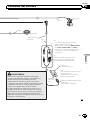
Dock
Connector
port
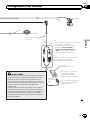
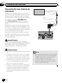
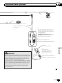
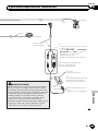
WARNING
· To avoid the risk of accident and the potential
violation of applicable laws, this product should never
be used while the vehicle is being driven except for
navigation purposes. And, also rear displays should
not be in a location where it is a visible distraction to
the driver.
· In some countries, the viewing of images on a display
inside a vehicle even by persons other than the driver
may be illegal. Where such regulations apply they
must be obeyed and this product’s video source
should not be used.
USB and mini-jack
connector
(
*
2)
— When connecting your iPod, both
connections are necessary.
— You must set “AV1 Input” in “AV
System Settings” to “iPod” when
connecting the iPod. (For details, refer
to Operation Manual.)
(
*
2)
USB Interface Cable for iPod
(CD-IU51V) (sold separately)
iPod with
Dock Connector (*3)
(*3)
For details concerning
operations and compatibility,
refer to Operation Manual.
2 m
4 m
Microphone
3.55 m
GPS aerial
(
*
1)
Connect either the USB Interface
Cable for iPod or an appropriate USB
storage device.
(
*
1)
Engb
9
English
Section
02
Connecting the system

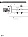
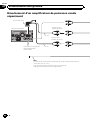
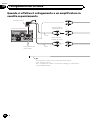
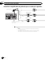
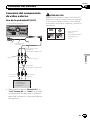
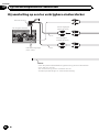
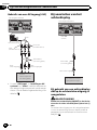
When connecting to separat ely sold power amp
The navigation unit
RCA connector
Subwoofer outputs
(SWL, SWR)
To system control terminal of the power amp
(max. 300 mA 12 V DC).
For connection, refer to the wiring and installation
manual separately supplied.
Blue
Rear outputs
(REAR OUTPUT)
Front outputs
(FRONT OUTPUT)
15 cm
15 cm
Engb
10
Section
02
Connecting the system

Left Right
System remote control
You can change the RCA output of the subwoofer depending on your subwoofer
system. (Refer to Operation Manual.)
Note
Power amp
(sold separately)
Power amp
(sold separately)
Power amp
(sold separately)
Front speaker Front speaker
Rear speaker Rear speaker
Subwoofer Subwoofer
RCA
cables
(sold separately)
Engb
11
English
Section
02
Connecting the system

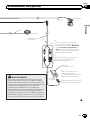
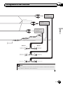
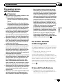
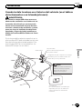
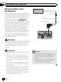
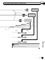
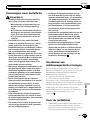
When connecting a rear
view camera
When this product is used with a rear view
camera, it is possible to automatically switch
from the video to rear view image when the
gearstick is moved to REVERSE (R). Rear
View mode also allows you to check what is
behind you while driving.
When you use a rear view camera, please be
sure to connect the violet/white lead. Other-
wise the rear view camera picture will not ap-
pear automatically when the vehicle is
reversing.
Instructions for proper connection of the vio-
let/white lead are contained in the wiring and
installation manual that is supplied separately.
WARNING
USE INPUT ONLY FOR REVERSE OR MIRROR
IMAGE REAR VIEW CAMERA. OTHER USE MAY
RESULT IN INJURY OR DAMAGE.
CAUTION
! The screen image may appear reversed.
! The rear view camera is used as an aid to
keep an eye on trailers, or backing into a tight
parking spot. Do not use this function for en-
tertainment purposes.
! Objects in rear view may appear closer or
more distant than in reality.
! Please note that the image area shown by the
rear view camera may differ slightly when full-
screen images are displayed when backing
and when checking the rear of the vehicle
while moving forward.
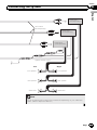
The navigation unit
20 cm
(e.g. ND-BC4)
(sold separately)
Rear view camera
To video output
RCA cable
Brown
(REAR VIEW CAMERA IN)
RCA connector
Notes
! This mode is available when the rear view
camera setting is set to “On”. (For details,
refer to Operation Manual.)
! Connect the navigation system to the rear
view camera only. Do not connect to any
other equipment.
Engb
12
Section
02
Connecting the system

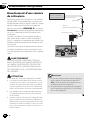
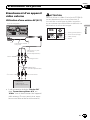
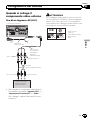
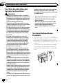
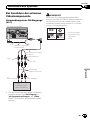
When connecting the
external video component
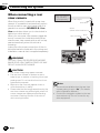
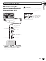
Using an AV input (AV1)
The navigation unit
RCA cables
(sold separately)
Yellow
Red, white
External video
component
(sold separately)
To video output
To audio outputs
Mini-jack AV cable
(CD-RM10)
(sold separately)
USB and
mini-jack connector
2 m
! You must set “AV1 Input” in “AV System
Settings” to “Video” when connecting the
external video component. (For details,
refer to Operation Manual.)
CAUTION
Be sure to use a mini-jack AV cable (CD-RM10)
(sold separately) for wiring. If you use other
cables, the wiring position might differ resulting
in disturbed images and sounds.
OK
G
V
R
L
G
R
V
L
L : Left audio (White)
R : Right audio (Red)
V : Video (Yellow)
G : Earth
Engb
13
English
Section
02
Connecting the system

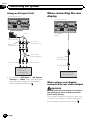
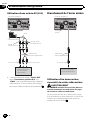
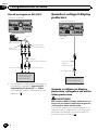
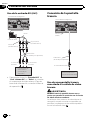
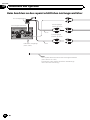
Using an AV input (AV2)
To audio outputs
Yellow
(VIDEO INPUT)
RCA connector
Red, white
(AUDIO INPUT)
RCA cables
(sold separately)
To video output
The navigation unit
External video
component
(sold separately)
20 cm
! You must set “AV2 Input” in “AV System
Settings” to “Video” when connecting the
external video component. (For details,
refer to Operation Manual.)
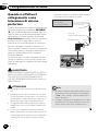
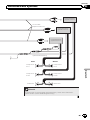
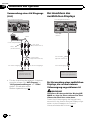
When connecting the rear
display
The navigation unit
Rear display with
RCA input jacks
Yellow
(VOUT)
RCA cable
(sold separately)
To video input
When using a rear display
connected to rear video output
WARNING
NEVER install the rear display in a location
that enables the driver to watch the video
source while driving.
This navigation system’s rear video output is for
connection of a display to enable passengers in
the rear seats to watch the video source.
Engb
14
Section
02
Connecting the system

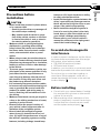
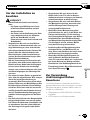
Precautions before
installation
CAUTION
! Never install this product in places where,
or in a manner that:
— Could injure the driver or passengers if
the vehicle stops suddenly.
— May interfere with the driver’s opera-
tion of the vehicle, such as on the floor
in front of the driver’s seat, or close to
the steering wheel or gearstick.
! Make sure there is nothing behind the
dashboard or panelling when drilling
holes in them. Be careful not to damage
fuel lines, brake lines, electronic compo-
nents, communication wires or power
cables.
! When using screws, do not allow them to
come into contact with any electrical lead.
Vibration may damage wires or insulation,
leading to a short circuit or other damage
to the vehicle.
! To ensure proper installation, use the sup-
plied parts in the manner specified. If any
parts other than the supplied ones are
used, they may damage internal parts of
this product or they may work loose and
the product may become detached.
! It is extremely dangerous to allow cables
to become wound around the steering col-
umn or gearstick. Be sure to install this
product, its cables, and wiring away in
such so that they will not obstruct or hin-
der driving.
! Make sure that leads cannot get caught in
a door or the sliding mechanism of a seat,
resulting in a short circuit.
! Please confirm the proper function of
your vehicle’s other equipment after in-
stallation of the navigation system.
! Do not install this navigation system
where it may (i) obstruct the driver’s vi-
sion, (ii) impair the performance of any of
the vehicle’s operating systems or safety
features, including airbags, hazard lamp
buttons or (iii) impair the driver’s ability
to safely operate the vehicle.
! Install the navigation system between the
driver’s seat and front passenger seat so
that it will not be hit by the driver or pas-
senger if the vehicle stops quickly.
! Never install the navigation system in
front of or next to the place in the dash-
board, door, or pillar from which one of
your vehicle’s airbags would deploy.
Please refer to your vehicle’s owner’s
manual for reference to the deployment
area of the frontal airbags.
To avoid electromagnetic
interference
In order to prevent interference, set the follow-
ing items as far as possible from this naviga-
tion system, other cables or leads:
! FM, MW/LW aerial and its lead
! GPS aerial and its lead
In addition, you should lay or route each aerial
lead as far as possible from other aerial leads.
Do not bind, lay or route them together, or
cross them. Electromagnetic noise will in-
crease the potential for errors in the vehicle's
location display.
Before installing
! Consult with your nearest dealer if installa-
tion requires drilling holes or other modifi-
cations of the vehicle.
! Before making a final installation of this
product, temporarily connect the wiring to
confirm that the connections are correct
and the system works properly.
Engb
15
English
Section
03
Installation

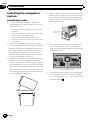
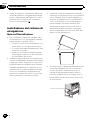
Installing the navigation
system
Installation notes
! Do not install the navigation system in
places subject to high temperatures or hu-
midity, such as:
— Places close to a heater, vent or air con-
ditioner.
— Places exposed to direct sunlight, such
as on top of the dashboard.
— Places that may be exposed to rain,
such as close to the door or on the vehi-
cle’s floor.
! Install this navigation system in an area
strong enough to bear its weight. Choose a
position where this navigation system can
be firmly installed, and install it securely. If
this navigation system is not securely in-
stalled, the current location of the vehicle
cannot be displayed correctly.
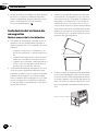
! Install the navigation unit horizontally on a
surface within 0 to 30 degrees tolerance
(within 5 degrees to the lef t or right). Impro-
per installation of the unit with the surface
tilted more than these tolerances increases
the potential for errors in the vehicle's loca-
tion display, and might otherwise cause re-
duced display performance.
30°
5° 5°
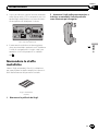
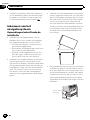
! When installing, to ensure proper heat dis-
persal when using this unit, make sure you
leave ample space behind the rear panel
and wrap any loose cables so they are not
blocking the vents.
5cmcm
Leave ample
space
5 cm
5 cm
! The cords must not cover the area shown
in the figure below. This is necessary to
allow the amps and navigation mechanism
to dissipate heat.
Do not cover this area.
! The semiconductor laser will be damaged
if it overheats, so don’t install the naviga-
tion unit anywhere hot — for instance, near
a heater outlet.
Engb
16
Section
03
Installation

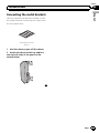
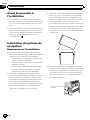
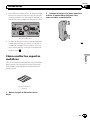
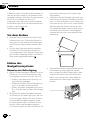
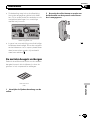
Concealing the metal brackets
Use the supplied self-adhesive sheets to hide
the metal brackets inside that are visible from
the front panel slits.
Self-adhesive sheet
(4 pcs.)
1 Peel the release paper off the sheets.
2 Attach the sheets at the top and bot-
tom on both sides of the panel as illu-
strated below.
Engb
17
English
Section
03
Installation

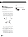
Installing the GPS aerial
CAUTION
Do not cut the GPS aerial lead to shorten it
or use an extension to make it longer. Alter-
ing the aerial cable could result in a short cir-
cuit or malfunction and permanent damage
to the navigation system.
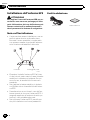
Installation notes
! The aerial should be installed on a level sur-
face where radio waves will be blocked as
little as possible. Radio waves cannot be re-
ceived by the aerial if reception from the sa-
tellite is blocked.
Dashboard Rear shelf
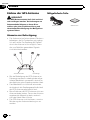
! When installing the GPS aerial inside the
vehicle, be sure to use the metal sheet pro-
vided with your system. If this is not used,
the reception sensitivity will be poor.
! Do not cut the accessory metal sheet. This
would reduce the sensitivity of the GPS aer-
ial.
! Take care not to pull the aerial lead when
removing the GPS aerial. The magnet at-
tached to the aerial is very powerful, and
the lead may become detached.
! Do not paint the GPS aerial, as this may af-
fect its performance.
Parts supplied
GPS aerial Metal sheet
Engb
18
Section
03
Installation

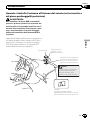
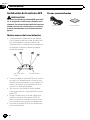
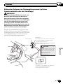
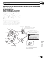
When installing the aerial inside the vehicle (on the dashboard or
rear shelf)
WARNING
Do not install the GPS aerial over any sen-
sors or vents on the dashboard of the vehicle,
as doing so may interfere with the proper
functioning of such sensors or vents and may
compromise the ability of the metal sheet
under the GPS aerial to properly and se-
curely affix to the dashboard.
Affix the metal sheet on the surface as level as
possible where the GPS aerial faces the win-
dow. Place the GPS aerial on the metal sheet.
(The GPS aerial is fastened with its magnet.)
The metal sheet contains a
strong adhesive which may
leave a mark on the surface if
it is removed.
Note
Clamps
Use separately sold clamps
to secure the lead where necessary
inside the vehicle.
GPS aerial
Metal sheet
Peel off the protective sheet
on the rear.
Make sure the surface is
free of moisture, dust,
grime, oil, etc., before
affixing the metal sheet.
Notes
! When attaching the metal sheet, do not cut
it into small pieces.
! Some models use window glass that does
not allow signals from GPS satellites to
pass through. On such models, install the
GPS aerial on the outside of the vehicle.
Engb
19
English
Section
03
Installation

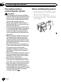
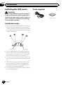
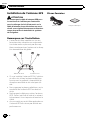
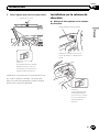
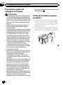
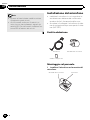
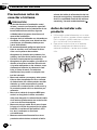
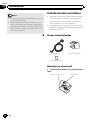
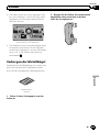
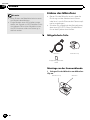
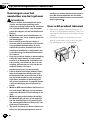
Installing the microphone
! Install the microphone in a place where its
direction and distance from the driver
make it easiest to pick up the driver’s voice.
! Make sure to connect the microphone to
the navigation system after the system is
turned off (ACC OFF).
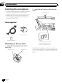
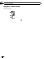
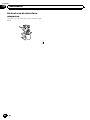
Parts supplied
Microphone Microphone clip
Double-sided tape
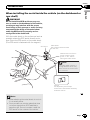
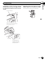
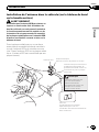
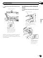
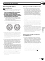
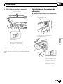
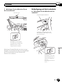
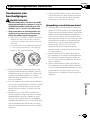
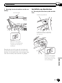
Mounting on the sun visor
1 Install the microphone in the micro-
phone clip.
Microphone clip Microphone
2 Attach the microphone clip to the sun
visor.
Microphone clip
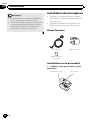
Clamps
Use separately sold clamps
to secure the lead where ne-
cessar y inside the vehicle.
Install the microphone on the sun visor when
it is in the up position. It cannot recognise the
driver’s voice if the sun visor is in the down po-
sition.
Engb
20
Section
03
Installation
La pagina sta caricando ...
La pagina sta caricando ...
La pagina sta caricando ...
La pagina sta caricando ...
La pagina sta caricando ...
La pagina sta caricando ...
La pagina sta caricando ...
La pagina sta caricando ...
La pagina sta caricando ...
La pagina sta caricando ...
La pagina sta caricando ...
La pagina sta caricando ...
La pagina sta caricando ...
La pagina sta caricando ...
La pagina sta caricando ...
La pagina sta caricando ...
La pagina sta caricando ...
La pagina sta caricando ...
La pagina sta caricando ...
La pagina sta caricando ...
La pagina sta caricando ...
La pagina sta caricando ...
La pagina sta caricando ...
La pagina sta caricando ...
La pagina sta caricando ...
La pagina sta caricando ...
La pagina sta caricando ...
La pagina sta caricando ...
La pagina sta caricando ...
La pagina sta caricando ...
La pagina sta caricando ...
La pagina sta caricando ...
La pagina sta caricando ...
La pagina sta caricando ...
La pagina sta caricando ...
La pagina sta caricando ...
La pagina sta caricando ...
La pagina sta caricando ...
La pagina sta caricando ...
La pagina sta caricando ...
La pagina sta caricando ...
La pagina sta caricando ...
La pagina sta caricando ...
La pagina sta caricando ...
La pagina sta caricando ...
La pagina sta caricando ...
La pagina sta caricando ...
La pagina sta caricando ...
La pagina sta caricando ...
La pagina sta caricando ...
La pagina sta caricando ...
La pagina sta caricando ...
La pagina sta caricando ...
La pagina sta caricando ...
La pagina sta caricando ...
La pagina sta caricando ...
La pagina sta caricando ...
La pagina sta caricando ...
La pagina sta caricando ...
La pagina sta caricando ...
La pagina sta caricando ...
La pagina sta caricando ...
La pagina sta caricando ...
La pagina sta caricando ...
La pagina sta caricando ...
La pagina sta caricando ...
La pagina sta caricando ...
La pagina sta caricando ...
La pagina sta caricando ...
La pagina sta caricando ...
La pagina sta caricando ...
La pagina sta caricando ...
La pagina sta caricando ...
La pagina sta caricando ...
La pagina sta caricando ...
La pagina sta caricando ...
La pagina sta caricando ...
La pagina sta caricando ...
La pagina sta caricando ...
La pagina sta caricando ...
La pagina sta caricando ...
La pagina sta caricando ...
La pagina sta caricando ...
La pagina sta caricando ...
La pagina sta caricando ...
La pagina sta caricando ...
La pagina sta caricando ...
La pagina sta caricando ...
La pagina sta caricando ...
La pagina sta caricando ...
La pagina sta caricando ...
La pagina sta caricando ...
La pagina sta caricando ...
La pagina sta caricando ...
La pagina sta caricando ...
La pagina sta caricando ...
La pagina sta caricando ...
La pagina sta caricando ...
La pagina sta caricando ...
La pagina sta caricando ...
La pagina sta caricando ...
La pagina sta caricando ...
La pagina sta caricando ...
La pagina sta caricando ...
La pagina sta caricando ...
La pagina sta caricando ...
La pagina sta caricando ...
La pagina sta caricando ...
La pagina sta caricando ...
La pagina sta caricando ...
La pagina sta caricando ...
La pagina sta caricando ...
-
 1
1
-
 2
2
-
 3
3
-
 4
4
-
 5
5
-
 6
6
-
 7
7
-
 8
8
-
 9
9
-
 10
10
-
 11
11
-
 12
12
-
 13
13
-
 14
14
-
 15
15
-
 16
16
-
 17
17
-
 18
18
-
 19
19
-
 20
20
-
 21
21
-
 22
22
-
 23
23
-
 24
24
-
 25
25
-
 26
26
-
 27
27
-
 28
28
-
 29
29
-
 30
30
-
 31
31
-
 32
32
-
 33
33
-
 34
34
-
 35
35
-
 36
36
-
 37
37
-
 38
38
-
 39
39
-
 40
40
-
 41
41
-
 42
42
-
 43
43
-
 44
44
-
 45
45
-
 46
46
-
 47
47
-
 48
48
-
 49
49
-
 50
50
-
 51
51
-
 52
52
-
 53
53
-
 54
54
-
 55
55
-
 56
56
-
 57
57
-
 58
58
-
 59
59
-
 60
60
-
 61
61
-
 62
62
-
 63
63
-
 64
64
-
 65
65
-
 66
66
-
 67
67
-
 68
68
-
 69
69
-
 70
70
-
 71
71
-
 72
72
-
 73
73
-
 74
74
-
 75
75
-
 76
76
-
 77
77
-
 78
78
-
 79
79
-
 80
80
-
 81
81
-
 82
82
-
 83
83
-
 84
84
-
 85
85
-
 86
86
-
 87
87
-
 88
88
-
 89
89
-
 90
90
-
 91
91
-
 92
92
-
 93
93
-
 94
94
-
 95
95
-
 96
96
-
 97
97
-
 98
98
-
 99
99
-
 100
100
-
 101
101
-
 102
102
-
 103
103
-
 104
104
-
 105
105
-
 106
106
-
 107
107
-
 108
108
-
 109
109
-
 110
110
-
 111
111
-
 112
112
-
 113
113
-
 114
114
-
 115
115
-
 116
116
-
 117
117
-
 118
118
-
 119
119
-
 120
120
-
 121
121
-
 122
122
-
 123
123
-
 124
124
-
 125
125
-
 126
126
-
 127
127
-
 128
128
-
 129
129
-
 130
130
-
 131
131
-
 132
132


Mode AVIC F9310 BT Manuale del proprietario
- Categoria
- Microfoni
- Tipo
- Manuale del proprietario
- Questo manuale è adatto anche per
in altre lingue
- français: Mode AVIC F9310 BT Le manuel du propriétaire
- español: Mode AVIC F9310 BT El manual del propietario
- Deutsch: Mode AVIC F9310 BT Bedienungsanleitung
- Nederlands: Mode AVIC F9310 BT de handleiding