ACO Light Shaft Assembly Instructions Manual
- Tipo
- Assembly Instructions Manual

Montageset
ACO Lichtschacht
begehbar
Art.-Nr. 35595
Montageanleitung
Achtung: Bitte auch Angaben im Prospekt beachten!
ACO Lichtschacht
ACO Hochbau Vertrieb GmbH Postfach 11 25 · 97661 Bad Kissingen · Neuwirtshauser Straße 14 · 97723 Oberthulba/Reith
Tel. 09736 41–60 · Fax 09736 41–20 · www.aco-hochbau.de
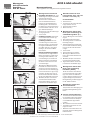
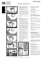
Montage ACO Lichtschacht
begehbar/befahrbar (a. – g.)
a. Vor Montage Rost einlegen und Rostab-
hebesicherung befestigen.
b. Anzeichnen der Lichtschachtober-
kante zur Geländeoberkante. Bei
Gebrauch der ACO Montagehilfe ist
OK Montagehilfe = OK Lichtschacht.
Der Abstand von Fensterunterkante bis
Lichtschachtboden sollte mind. 15 cm
(gem. DIN 18195) betragen
c. Anzeichnen der zwei oberen Bohrungen
mit eingelegtem Rost
d. Löcher bohren
e. Ausführung begehbar: Dübel setzen
und Lichtschacht anschrauben. Ggf.
Schlitzscheibe einsetzen.
Ausführung befahrbar: Die Licht-
schachtmontage muss direkt an der
Kellerwand erfolgen. Schwerlastanker
mit aufgeschraubter Mutter einschla-
gen. Mutter entfernen, Lichtschacht
einhängen, mit Scheibe und Mutter
festschrauben
Montage auf Dämmung begehbar:
Schwerlastanker mit aufgeschraubter
Mutter durch Dämmung in Kellerwand
einschlagen. Mutter entfernen, Licht-
schacht einhängen, mit Scheibe und
Mutter festschrauben. Anschließend
die unteren Löcher bohren und Licht-
schacht befestigen.
f. Mit homogenen Material lagenweise
hinterfüllen und verdichten. Beim Ver-
dichten muss der Rost eingelegt sein.
Den Abstand zwischen Verdichtungsge-
rät und Lichtschacht von Lage zu Lage
vergrößern. Die letzte Lage rund um
den Lichtschacht händisch verdichten.
Hierbei ist die DIN 18300 zu beachten.
g. Mit Rüttler, Stampfer und schwerem
Gerät ausreichend Abstand halten.
Angrenzendes Pflaster rund um den
Lichtschacht in ein Mörtelbett legen.
9-29
Verstellbereich in cm
37-58
65-86
a.
b.
c.
d.
e.
g.
h.
4002626 355959
max. 12 cm
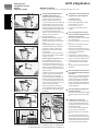
e.2
Höhenkorrektur für ACO
Lichtschächte 100 x 100 x 40
und 100 x 130 x 40 (e. 2)
Vor dem Verfüllen
1. Schrauben lösen
2. Lichtschacht in die gewünschte Höhe
bringen (maximal +12 cm)
3. Schrauben wieder anziehen
4. Weiter mit Punkt „f“
Montage ACO Aufstockele-
ment (alte Ausführung) aus-
schließlich begehbar: (h.)
1. Erst nach Montage des Lichtschachtes
möglich
2. Rost in Aufstockelement einlegen.
3. Aussteifungsrahmen in Lichtschacht-
Rostauflage einlegen.
4. Gewünschte Höhe durch Aufstockele-
ment herstellen. Die Höhenverstellung
kann nur über das unterste Element
erfolgen.
5. Löcher bohren
6. Aufstockelemente verschrauben.
7. Mit homogenen Material wie unter
Punkt f. beschrieben hinterfüllen und
verdichten.
8. Mit Rüttler, Stampfer und schwerem
Gerät ausreichend Abstand halten.
9. Angrenzendes Pflaster rund um den
Lichtschacht in ein Mörtelbett legen.
Montage ACO Aufstockele-
ment (alte Ausführung)
befahrbar: (Bild h.)
Nur bei 40 cm tiefen Lichtschächten
und mit einem Element möglich. Mon-
tage muss direkt an der Kellerwand
erfolgen. Montage auf Dämmung nicht
möglich. Montage entsprechend der
Montageanleitung aus Befestigungsset
Art.-Nr. 35908 vornehmen
Montage der neuen ACO
Aufstockelemente
entsprechende der im Befestigungsset
beigefügten Montageanleitung durch-
führen
weitere wichtige Hinweise:
• LichtschächteoderAufstockelemente
im unverfüllten Zustand nicht belasten.
• LichtschachtwährendderBauphase
vor herabfallenden Gegenständen
schützen.
• BeimVerdichtenimmerRosteinsetzen.
• verdichtetesErdreichkannsichnach
einiger Zeit setzen
• BefahrbareLichtschächtekönnennur
längsseitig (parallel zur Montagewand)
befahren werden.
min. 1 m

max. 12 cm
Assambly unit
ACO Light Shaft
for Pedestrian
Article No. 35595
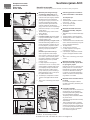
plant.
h. Lay the surrounding paving around the
Light Shaft in a mortar bed.
Height adjustment for Light
Shafts 100 x 100 x 40 +
100 x 130 x 40
Prior to backfilling:
1. Loosen screws.
2. Position Light Shaft at the required
height (max. + 12 cm)
3. Retighten the screws.
4. Continue from instruction “f”
Assembly ACO Raising Element
(old model) pedestrian only:
1. Only possible after the Light Shaft has
been assembled.
2. Place the grid in the Raising Element.
3. Position stiffening frame in the Light
Shaft grid seat.
4. Adjust to the desired height by using the
Raising Element. The height can only be
adjusted using the lowest element.
5. Drill the holes.
6. Bolt the Raising Element into position.
7. Backfill carefully in layers with homoge-
neous material, and then compact as
described in instruction “f”.
8. Keep a proper distance away with the
vibrating plate, tamper and heavy plant.
9. Lay the surrounding paving around the
Light Shaft in a mortar bed.
Assembly ACO Raising Element
(old model) light vehicle:
Only possible with 40 cm deep Light
Shaft and with one element. Assemble
directly on cellar wall only. NOT possible
to assemble on insulation. Assemble in
accordance with the assembly instruc-
tions in fixing set Art.-No. 35908.
Assembly of the new ACO
Raising Element
Assemble in accordance with the
assembly instructions in the fixing set.
Importantinstructions:
• LightShaftsorRaisingElements.Donot
apply loads to Light Shafts or Raising
Elements before they are backfilled.
• ProtectLightShaftsfromfallingobjects
during the construction phase.
• Duringcompaction,alwaysplacethe
grid in position or use the stiffening
frame.
• Thecompactedsoilmaysettleafter
some time.
• LightvehicleLightShaftsshouldonly
be driven over longitudinally (parallel to
the assembly wall). Completely driving
over the Light Shaft only possible in
agreement with the ACO Applications
Engineering Department.
Assembly instructions
Note: These assembly instructions to be read in conjunction with the sales brochure.
ACO Light Shaft
ACO Technologies plc · Hitchin Road · UK-Shefford · Beds. SG 17 5TE
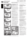
Assembly ACO Light Shaft for
pedestrian/light vehicle (a.-h.)
a. Before securing the Light Shaft in
position, insert the grid and fix the grid
fastener to the Light Shaft.
b. Mark the position of the unit so that the
top edge of the Light Shaft is equal to
the finished surface of the ground level.
When using the ACO assembly aid, the
upper edge of the assembly aid should
equal the top edge of the Light Shaft.
The distance between the lower edge
of the window to the base of the Light
Shaft should be at least 15 cm (pursu-
ant to DIN 18195).
c. Mark the two upper fixing holes with
inserted grid.
d. Drill the holes.
e. Pedestrian model: Insert the dowels,
and bolt on the Light Shaft. Use slotted
washers if necessary.
Light vehicle model: The Light Shaft
must be installed directly on the cellar
wall. Bang in the heavy duty anchors
with the screwed on nuts. Remove the
nuts, hang in the Light Shaft, bolt on
with the washer and the nuts.
Assembly on insulation pedestrian:
Bang in the heavy duty anchors with the
screwed on nuts through the insulation
and into the cellar wall. Remove the
nuts, hang in the Light Shaft, bolt on
with the washer and the nuts. Then drill
the lower holes and fasten the Light
Shaft into position.
f. Backfill carefully in layers with homo-
geneous material, and then compact.
The grid has to be in position during
the compaction process. The distance
between the compactor and the Light
Shaft should become larger as each
higher layer is compacted. The top
layer around the Light Shaft should be
compacted manually. This should be
done in accordance with the regula-
tions in DIN 18300.
g. Keep a proper distance away with
the vibrating plate, tamper and heavy
9-29
37-58
65-86
a.
b.
c.
d.
e.
g.
h.
min. 1 m
4002626 355959
e.2

max. 12 cm
Ensemble de montage
d’une cour anglaise
ACO praticable
Reference 35595
h. Poser le pavage adjacent autour de la cour
anglaise dans un lit de mortier.
Correction de la hauteur de la
cour anglaise 100 x 100 x 40 +
100 x 130 x 40
Avant de reboucher:
1. Dévisser les vis.
2. Mettre la cour anglaise à la hauteur souhai-
tée (max. + 12 cm)
3. Revisser les vis.
4. Poursuivre avec le point « f »
Montage d’éléments de rehausse
ACO (ancien modèle) exclusive-
ment à usage piéton:
1. Possible uniquement après le montage de
la cour anglaise.
2. Poser la grille dans l’élément de rehausse.
3. Insérer la structure de renforcement dans le
support de grille de la cour anglaise.
4. Régler la hauteur souhaitée à l’aide de l’élé-
ment de rehausse. Le réglage de la hauteur
peut uniquement être effectué par le biais
de l’élément le plus bas.
5. Percer les trous.
6. Visser les éléments de rehausse.
7. Remplir avec un matériau homogène dans
le sens de la longueur et compacter.
8. Maintenir un écart suffisant avec le
secoueur, le pilon et l’engin lourd.
9. Poser le pavage adjacent autour de la cour
anglaise dans un lit de mortier.
Montage d’éléments de rehausse
ACO (ancien modèle) carros-
sables: Montage ACO
Possible uniquement avec une cour
anglaise de 40 cm de profondeur et avec
un seul élément. Le montage doit être
effectué directement sur le mur de sous-
sol. Il n’est pas possible d’effectuer le mon-
tage sur une isolation. Procéder au mon-
tage de façon conforme aux instructions de
montage du kit de fixation N° d’art. 35908.
Montage des nouveaux éléments
de rehausse ACO
Effectuer le montage de façon conforme
aux instructions de montage incluses dans
le kit de fixation.
Remarquesimportantes:
• CoursanglaisesourehaussesNepaschar-
ger les cours anglaises ou les éléments de
rehausse lorsque ceux-ci se trouvent à l’état
non rempli.
• Durantlaphasedeconstruction,protéger
la cour anglaise contre les objets pouvant
tomber.
• Toujoursutiliserunegrilleouunestructure
de renforcement lors du compactage.
• Laterrecompactéepeuts’affaisseraprès
quelques temps.
• Lesvéhiculespeuventuniquementpasser
sur les cours anglaises carrossables dans
le sens de la longueur (parallèle à la paroi
préfabriquée). Les véhicules peuvent uni-
quement passer entièrement sur les cours
anglaises après accord avec le service de
technique d’application ACO.
Instructionsdemontage
Attention : respecter également les indications figurant dans la notice.
Cours anglaises ACO
ACO Produits Polymères S.A. · Le Quai à Bois · B.P. 85 · F-27940 Notre Dame de l’Isle
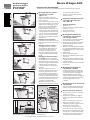
Montage d’une cour anglaise
ACO à usage piéton ou carros-
sable (figures a. - h.)
a. Avant le montage, poser la grille sur la
coque et fixer le système antieffraction
de la grille.
b. Repérer sur le mur le bord supérieur
de la cour anglaise correspondant au
niveau du sol fini. En cas d’utilisation du
gabarit de montage ACO, le bord supé-
rieur du gabarit = le bord supérieur de
la cour anglaise. L’espace entre le bord
inférieur de la fenêtre et le fond de la
cour anglaise doit être d’au moins 15
cm (cf. DIN 18195).
c. Repérer les deux trous de fixation supé-
rieurs avec la grille insérée.
d. Percer les trous.
e. Modèle à usage piéton: Mettre les
chevilles et visser la cour anglaise.
Le cas échant, mettre une rondelle à
fente.
Modèle carrossable: Le montage de
la cour anglaise doit s’ensuivre direc-
tement sur le mur de la cave. Enfoncer
les goujons d’ancrage pour fixations
lourdes avec l’écrou vissé. Enlever
l’écrou, accrocher la cour anglaise puis
visser à bloc à l’aide d’une rondelle et
d’un écrou.
Montage sur une isolation prati-
cable: Enfoncer les goujons d’ancrage
pour fixations lourdes avec l’écrou
vissé à travers l’isolation dans le mur
de sous-sol. Enlever l’écrou, accrocher
la cour anglaise puis visser à bloc à
l’aide d’une rondelle et d’un écrou. Per-
cer ensuite les trous inférieurs et fixer
la cour anglaise.
f. Remplir avec un matériau homogène
dans le sens de la longueur et compac-
ter. Lors du compactage, la grille doit
être insérée. Augmenter l’écart entre
l’appareil de compactage et la cour
anglaise de couche en couche. Com-
pacter à la main la dernière couche
autour de la cour anglaise. Il faut y
observer la norme DIN 18300.
g. Maintenir un écart suffisant avec le
secoueur, le pilon et l’engin lourd.
9-29
37-58
65-86
a.
b.
c.
d.
e.
g.
h.
min. 1 m
4002626 355959
e.2

max. 12 cm
9-29
Verstellbereich in cm
37-58
65-86
Kit di montaggio
per bocca di lupo
ACO pedonale
N. art. 35595
ni, il pestello e la piastra vibrante.
h. Lastricare su letto di malta il perimetro
della bocca di lupo.
Regolazione dell'altezza per boc-
che di lupo 100 x 100 x 40 +
100 x 130 x 40
Prima del riempimento:
1. Allentare le viti.
2. Portare la bocca di lupo all'altezza deside-
rata (max. + 12 cm)
3. Serrare di nuovo le viti.
4. Proseguire con il punto "f"
Montaggio dell’elemento di
sopralzo ACO, solo pedonale
(versione precedente):
1. Il montaggio può essere eseguito soltanto
dopo aver montato la bocca di lupo.
2. Montare la griglia nell’elemento di sopralzo.
3. Introdurre un telaio di rinforzo in ciascun
elemento di sopralzo.
4. Realizzare un sopralzo dell’altezza desidera-
ta. La regolazione dell'altezza potrà essere
realizzata solo dopo aver svolto le operazio-
ni che seguono.
5. Praticare i fori.
6. Avvitare l'elemento di sopralzo.
7. Riempire con materiale omogeneo e costi-
pare a strati.
8. Mantenere la necessaria distanza durante
l'uso del costipatore a vibrazioni, il pestello
e la piastra vibrante.
9. Lastricare su letto di malta il perimetro della
bocca di lupo.
Montaggio dell’elemento di
sopralzo ACO, carrabile:
Il montaggio del sopralzo è possibile solo
con bocche di lupo di 40 cm di profondità
e con un unico elemento. Il montaggio va
realizzato direttamente sulla parete del
sotterraneo. Non è possibile il montaggio su
isolamento. Seguire le istruzioni di montag-
gio e di fissaggio indicate per l'Art.
nº 35908.
Montaggio del nuovo elemento di
sopralzo ACO:
Seguire le istruzioni riportate nel libretto di
istruzioni corrispondente al kit di fissaggio.
Ulteriori istruzioni di rilievo:
• Noncaricarebocchedilupooelementidi
sopralzo non riempiti.
• Durantelafasecostruttivaproteggere
la bocca di lupo dall’eventuale caduta di
oggetti.
• Infasedicostipazionefaresempreuso
della griglia o del telaio di rinforzo.
• Ilmaterialecostipatoèsoggettoadasse-
stamenti dopo un certo periodo.
• Lebocchedilupocarrabili,potranno
essere percorse solo nel senso della lun-
ghezza (ovvero parallelamente alla parete
di montaggio). Lo schiacciamento totale
va discusso e autorizzato solo dopo una
consulenza tecnica dell’azienda ACO.
Istruzioniperilmontaggio
Attenzione: osservare anche le indicazioni contenute nel prospetto.
a.
b.
c.
d.
e.
g.
h.
Bocca di Lupo ACO
ACO Passavant S. p. A. · Via Lazio 2 · I-40060 Osteria Grande (Bologna)
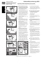
Montaggio della bocca di lupo
ACO pedonale/carrabile
(figure a.-h.)
a. Prima del montaggio, collocare la
griglia e fissare il corrispondente dispo-
sitivo di sicurezza.
b. Tracciare il filo superiore della bocca di
lupo al livello di calpestio. Se si utilizza il
calibro ACO per il montaggio, conside-
rare che il bordo superiore del calibro
(OK) deve corrispondere al bordo
superiore della bocca di lupo (OK). La
distanza tra il filo inferiore della finestra
e il fondo della bocca di lupo deve esse-
re di min. 15 cm (secondo DIN 18195).
c. Segnare i punti in cui vanno praticati i 2
fori superiori con la griglia in posizione.
d. Praticare i fori.
e. Montaggio versione pedonale:
collocare i tasselli e avvitarvi la bocca di
lupo. Collocare le corrispondenti rondel-
le Grover.
Montaggio versione carrabile: Il
montaggio della bocca di lupo deve
essere effettuato direttamente sulla
parete dello scantinato. Collocare i
tasselli per ancoraggi pesanti con i
dadi svitati. Togliere i dadi, appendere
la griglia e fissare avvitando i dadi dei
tasselli.
Montaggio su isolamento pedona-
le/carrabile: collocare i tasselli per
ancoraggi pesanti con i dadi svitati sulla
parete del sotterraneo. Togliere i dadi,
appendere la griglia e fissare avvitando
i dadi dei tasselli. Successivamente,
praticare i fori inferiori e fissare la boc-
ca di lupo.
f. Riempire e costipare a strati con
materiale omogeneo. Durante la costi-
pazione, la griglia deve essere collo-
cata. Aumentare progressivamente la
distanza tra la macchina operatricee la
bocca di lupo. Nelle immediate vicinan-
ze e attorno alla bocca di lupocostipare
il materiale manualmente. Il lavoro va
eseguito a norma DIN 18300.
g. Mantenere la necessaria distanza
durante l'uso del costipatore a vibrazio-
9-29
37-58
65-86
a.
b.
c.
d.
e.
g.
h.
min. 1 m
4002626 355959
e.2

max. 12 cm
Zestaw do montażu
doświetlaczy okiennych ACO
(dopuszcza się ruch pieszy)
Numer art. 35595
g. W celu zachowania wystarczającego
odstępu użyć sprzętu do zagęszczania
wibrowaniem, ubijaka i ciężkiego sprzętu.
h. Nawierzchnię brukową wokół doświetlacza
umieścić w podłożu z zaprawy.
Dobranie odpowiedniej wysokości
montażowej doświetlacza ACO
100x100x40 i 100x130x40
Przed zasypaniem:
1. Poluzować śruby.
2. Doświetlacz ustawić na pożądaną wyso-
kość (maksymalnie + 12 cm)
3. Na zakończenie śruby ponownie dokręcić.
4. Dalej patrz punkt „f”
Montaż nadstawki ACO (stara wer-
sja), dopuszczalny wyłącznie ruch
pieszy:
1. Możliwy dopiero po montażu doświetlacza.
2. Ruszt włożyć w nadstawkę.
3. W nadstawkę włożyć ramę wzmacniającą.
4. Ustawić nadstawkę na żądanej wysokości.
Wysokość można regulować wyłącznie
powyżej najniżej umieszczonego elemen-
tu.
5. Wywiercić otwory.
6. Nadstawki przymocować za pomocą śrub.
Montaż nadstawki ACO (stara wer-
sja), dopuszczalny wyłącznie prze-
jazd samochodem:
Możliwy wyłącznie w przypadku doświe-
tlaczy o głębokości 40 cm oraz z jednym
elementem. Montaż musi być przeprowa-
dzony bezpośrednio na ścianie piwnicy.
Montaż na izolacji nie jest możliwy. Montaż
przeprowadzić zgodnie z instrukcją mon-
tażu dołączoną do zestawu mocującego nr
art. 35908.
Montaż nowych nadstawek ACO
Montaż przeprowadzić zgodnie z instruk-
cją montażu dołączoną do zestawu mocu-
jącego.
Ważne wskazówki:
1. Doświetlacze lub nadstawki: Nie obciążać
doświetlaczy lub nadstawek przed zasypa-
niem.
2. W trakcie budowy chronić doświetlacze
przed spadającymi przedmiotami.
3. Podczas zagęszczania zawsze stosować
ruszt lub ramę wzmacniającą.
4. Zagęszczony grunt może po pewnym cza-
sie obsiąść.
5. W przypadku doświetlaczy w wersji z
dopuszczalnym przejazdem samochodem
możliwy jest przejazd wyłącznie wzdłuż
(równolegle do ściany montażowej). Pełny
przejazd należy ustalić z ekspertami ds.
techniki stosowania ACO.
Instrukcja montażu doświetlaczy okiennych ACO
Uwaga: Prosimy również uwzględnić informacje w prospekcie!
Doświetlacz okienny ACO
ACO Elementy Budowlane Sp. z o.o. · ul. Fabryczna 5 · Lajski · PL-05 119 Legionowo
Tel. 0048/22 76 70 500 · Fax 0048/22 76 70 513 · [email protected]
Montaż doświetlaczy okiennych
ACO, dopuszcza się ruch pieszy/
dopuszcza się przejazd samocho-
dem osobowym (rysunki a-h)
a. Przed montażem włożyć ruszt i przymo-
cować zabezpieczenie rusztu.
b. Zaznaczyć górną krawędź doświetlacza,
która powinna być zgodna z powierzch-
nią terenu. Górna krawędź zaznaczona
na pomocy montażowej ACO = górna
krawędź doświetlacza. Odstęp od dolnej
krawędzi okna do dna doświetlacza
powinien wynosić przynajmniej 15 cm
(zgodnie z DIN 18195).
c. Na ścianie, z założonym rusztem, wytra-
sować 4 otwory.
d. Wywiercić otwory.
e. Wersja z dopuszczeniem ruchu pie-
szy: włożyć kołki rozporowe i przykręcić
doświetlacz. W razie potrzeby założyć
podkładki szczelinowe.
Wersja z dopuszczeniem przejazdu
samochodem: Doświetlacz okienny
montuje się bezpośrednio na ścianie w
piwnicy: wbić kotwy do dużych ciężarów
z nakręconymi nakrętkami.
Zdjąć nakrętki, zawiesić doświetlacz,
przykręcić przy użyciu podkładki i
nakrętki.
Montaż na izolacji (dopuszcza się
ruch pieszy): wbić kotwy do dużych
ciężarów z nakręconymi nakrętkami,
przechodzące przez ścianę w piwnicy.
Zdjąć nakrętki, zawiesić doświetlacz,
przykręcić przy użyciu podkładki i nakręt-
ki. Na koniec wywiercić dolne otwory i
zamocować doświetlacz.
f. Zasypywać warstwami z jednoczesnym
zagęszczaniem, używając jednorodnego
gruntu. Przy zagęszczaniu ruszt musi
być założony. Odstęp między maszy-
ną do zagęszczania a doświetlaczem
zwiększać w miarę zasypywania kolej-
nych warstw. Ostatnią warstwę wokół
oświetlacza zagęścić ręcznie. Przestrze-
gać przy tym DIN 18300.
9-29
37-58
65-86
a.
b.
c.
d.
e.
g.
h.
min. 1 m
4002626 355959
e.2

max. 12 cm
9-29
37-58
65-86
Montážní sada
pochozího
světlíku ACO
obj. č. 35595
Výšková korekce pro světlíky
100x100x40 a 100x130x40
Před zasypáním:
1. Povolte šrouby.
2. Světlík umístěte do požadované výš-
ky (max. + 12 cm)
3. Šrouby opět utáhněte.
4. Pokračujte bodem „f“.
Montáž výlučně pochozích
nástavců ACO (staré provedení):
1. Montáž je možná až po montáži svět-
líku.
2. Vložte do nástavce rošt.
3. Do nástavce světlíku vložte výztužný
rám.
4. Pomocí nástavců vytvořte požadova-
nou výšku. Výškové nastavení se dá
provést jen přes nejspodnější násta-
vec.
5. Vyvrtejte díry.
6. Přišroubujte nástavce.
7. Po vrstvách zasypejte homogenním
materiálem a udusejte – viz popis v
bodu f.
8. Při práci s vibrátorem, pěchovadlem
a těžkým přístrojem udržujte dosta-
tečný odstup.
9. Dlažbu kolem světlíku položte do
maltového lože.
Montáž pojezdných nástavců
ACO (staré provedení):
Možná jen u světlíků 40 cm hlubo-
kých a s jedním nástavcem. Montáž
se musí provést přímo na stěnu skle-
pa. Není možná montáž na izolaci.
Montáž proveďte podle Montážního
návodu z upevňovací soupravy art.
č. 35908.
Montáž nových nástavců ACO
Montáž proveďte podle Montážního
návodu přiloženého v upevňovací
soupravě.
Důležitá upozornění:
• Světlíky nebo nástavce nezatěžujte v
nezasypaném stavu
• Během montáže chraňte světlíky
před spadlými předměty
• Při zhutňování mějte vždy vsazený
rošť nebo výztužný rám.
• Zhutněná zemina se může po určité
době sesedat.
• Po pojezdných světlíkách se může
jezdit jen v podélném směru (rovno-
běžně se stěnou namontování. Úplné
přejíždění je možné jen po dohodě s
oddělením aplikované techniky firmy
ACO (ACO Anwendungstechnik).
ACO světlík - návod k montáži
Pozor: Prosíme o dodržení instrukcí v letáku !
ACO světlík
ACO Stavební prvky k.s. · Havlíčkova 260 · CZ-582 22 Přibyslav
Tel. 00420/569 491 234 · Fax 00420/569 482 533 · [email protected]
Montáž pochozího/pojezdného
světlíku ACO (obrázek a. - h.)
a. Před montáží vložte rošt a upevněte
pojistku proti zvednutí.
b. Označte polohu horní hrany světlíku
tak, aby byla v úrovni terénu. Při pou-
žití montážní pomůcky ACO je horní
hrana montážní pomůcky zároveň s
horní hranou světlíku. Vzdálenost od
spodní hrany okna ke dnu světlíku by
měla být nejméně 15 cm (podle DIN
18195).
c. S vloženým roštem označte dvě hor-
ní díry.
d. Vyvrtejte díry
e. Pochozí provedení: Vložte hmož-
dinky a přišroubujte světlík. Případně
použijte podložky s výřezem.
Pojezdné provedení: Montáž svět-
líku se musí provést přímo na stěnu
sklepa. Zatlučte kotvy pro vysoké
zatížení s našroubovanými maticemi.
Odšroubujte matice, zavěste světlík
a utáhněte maticemi s podložkami.
Montáž na pochozí izolaci: Zatlučte
kotvy pro vysoké zatížení s našrou-
bovanými maticemi skrz izolaci do
stěny sklepa. Odšroubujte matice,
zavěste světlík a utáhněte maticemi
s podložkami. Poté vyvrtejte spodní
díry a světlík upevněte.
f. Po vrstvách zasypejte homogenním
materiálem a udusejte. Při zhutňo-
vání zeminy musí být vložený rošt.
Vzdálenost mezi zhutňovacím pří-
strojem a světlíkem vrstvu po vrstvě
zvětšujte. Poslední vrstvu kolem
světlíku udusejte ručně. Respektujte
přitom normu DIN 18300.
g. Při práci s vibrátorem, pěchovadlem
a jiným těžkým přístrojem udržujte
dostatečný odstup.
h. Dlažbu kolem světlíku položte do
maltového lože.
a.
b.
c.
d.
e.
g.
h.
min. 1 m
4002626 355959
e.2

max. 12 cm
9-29
37-58
65-86
ACO Magyarország Bt. · Jászeberényi út 38-72 · A épület II. emelet · H-1106 Budapest
Tel. 0036/12 60 98 82 · Fax 0036/12 6070 52 · [email protected]
ACO gyalogos
világítóakna szerelő
készlet
Cikkszám: 35595
100x100x40 + 100x130x40 méretű
világítóaknák magasságállítása
Visszatemetés előtt:
1. Lazítsa meg a csavarokat.
2. Állítsa a kívánt magasságba a világító
aknát (legfeljebb + 12 cm rel).
3. Húzza meg a csavarokat.
4. Folytassa a normál szerelési leírás „f”
pontjával.
ACO aknamagasító elem besze-
relése (korábbi kivitelű) kizárólag
gyalogos terhelés esetén:
1. Csak az akna beépítése után szerelhető
fel az aknamagasító.
2. Helyezze a fedőrácsot a magasító elem-
be.
3. Helyezze a merevítő keretet az akna a
világítóakna rácstartójába.
4. Állítsa be a kívánt magasságot a maga-
sító elemmel. A magasság csak a legalsó
elemen keresztül végezhető el.
5. Fúrjon lyukakat.
6. Csavarozza be a magasító elemeket.
7. A feltöltést homogén anyaggal rétegesen
végezze, majd tömörítse a töltőanyagot.
8. Tartsa be a biztonságos távolságot a
nehéz gépektől (pl. rázógép, döngölő-
gép).
9. Az akna körüli kövezetet habarcságyba
kell fektetni
ACO aknamagasító elem beszere-
lése (korábbi kivitelű) járműterhe-
lés esetén:
Csak 40 cm mély világítóaknák esetében
és egy magasító elemmel lehetséges.
Az elemet közvetlenül a pincefalra kell
felszerelni. Szigetelésre nem lehet fel-
szerelni. A szerelést a 35908 cikkszámú
rögzítő készlet szerelési útmutatója sze-
rint kell végrehajtani.
Az új kivitelű ACO aknamagasító
elemek beszerelése
A szerelést a rögzítő készlethez mellékelt
szerelési útmutató szerint kell végrehaj-
tani.
További fontos tudnivalók:
• A világítóaknát vagy aknamagasító ele-
met nem szabad terhelés alá helyezni.
• A világítóaknát védeni kell az építés köz-
ben leeső tárgyak ellen.
• Tömörítés során mindig használni kell
egy rácsot vagy merevítő keretet.
• A tömörített föld egy idő után rendeződ-
het.
• A járművel terhelhető világítóaknákra
csak a hosszanti oldal mentén (a szerelé-
si fallal párhuzamosan) szabad ráhajtani.
A teljes ráhajtás előtt kérjen tanácsot az
ACO Anwendungstechnik vállalattól.
Beépítési utasítás
Figyelem: Kérjük tartsák be a használati utasítás előírásait !
ACO világítóakna
ACO gyalogos/járműterheléses
világítóakna beépítése (a.-h.)
a. Szerelés előtt helyezze a fedőrácsot az
aknába és rögzítse a rácsrögzítővel.
b. Jelölje be az akna felső peremét úgy,
hogy az ablak alsó pereme és az akna alja
között legalább 15 cm legyen a távolság
(a DIN 18195 szabvány szerint). Az ACO
beépítési segédeszköz használata esetén
beépítési segédeszköz felső széle legyen
egy szintben az akna felső szélével.
c. Jelölje be a két felső furat helyét úgy, hogy
közben a rács be van helyezve.
d. Készítse el a furatokat.
e. Gyalogos terhelés esetén: Illessze be
a tipliket, és csavarozza fel az aknát.
Szükség esetén rakja be a hasított alátét-
lemezt.
Járműterhelés esetén: A világítóakna
szerelést közvetlenül a pincefal mellett
kell elvégezni. Üsse be a falba a nagy
terhelésű horgonycsavart a rácsavart
anyával együtt.
Vegye le az anyát, akassza be az aknát,
majd rögzítse szilárdan a hasított alátétle-
mezzel és az anyával.
Beépítés gyalogos szigetelésre: Üsse
be a szigetelésen keresztül a pince
falba a nagy terhelésű horgonycsavart
a rácsavart anyával együtt. Vegye le az
anyát, akassza be az aknát, majd rögzítse
szilárdan a hasított alátétlemezzel és az
anyával. Végül fúrja ki az alsó furatokat és
rögzítse az aknát.
f. A feltöltést homogén anyaggal rétegesen
végezze, majd tömörítse a töltőanyagot.
Tömörítés közben be kell helyezni a
rácsot. A tömörítő gép és a világítóaknak
közötti távolságot rétegenként kell növel-
ni. Az utolsó réteget kézzel kell tömöríteni
az akna körül. Itt vegye figyelembe a DIN
18300 sz. szabvány előírásait.
g. Tartsa be a biztonságos távolságot a
nehéz gépektől (pl. rázógép, döngölőgép).
h. Az akna körüli kövezetet habarcságyba
kell fektetni.
a.
b.
c.
d.
e.
g.
h.
min. 1 m
4002626 355959
e.2

max. 12 cm
9-29
37-58
65-86
Komplet za montažo
pohodnih svetlobnih
jaškov ACO
Št. art. 35595
Višinski popravek za svetlobne
jaške 100x100x40 + 100x130x40
Pred zapolnitvijo:
1. Odvijte vijake.
2. Svetlobni jašek namestite na želeno
višino (najv. + 12 cm)
3. Ponovno privijte vijake.
4. Nadaljujte s točko »f«.
Montaža višinskih elementov
ACO (stara izvedba), izključno
pohodno:
1. Mogoče šele po montaži svetlobnega
jaška.
2. Položite rešetko v višinski element.
3. Položite povezni okvir v rešetko sve-
tlobnega jaška.
4. Z višinskimi elementi ustvarite želeno
višino. Višinska nastavitev je mogoča
samo z najnižjim elementom.
5. Izvrtajte izvrtine.
6. Privijte višinske elemente.
7. Po slojih zapolnite s homogenim
materialom in stisnite.
8. Z vibratorjem, nabijalnikom in težko
napravo ohranjajte zadostno razda-
ljo.
9. Mavec okoli svetlobnega jaška zalijte
z malto.
Montaža višinskih elementov
ACO (stara izvedba), preko kate-
rih je mogoče peljati:
Mogoče samo pri 40 cm globokih sve-
tlobnih jaških in z enim elementom.
Montaža se mora izvesti neposredno
na kletni zid. Montaža na izolacijo
ni mogoča. Pri montaži postopajte v
skladu z navodili za montažo pritrdil-
nega seta št. art. 35908.
Montaža novih višinskih elemen-
tov ACO
Pri montaži postopajte v skladu z
navodili za montažo, priloženimi pritr-
dilnemu setu.
Pomembni napotki:
• Svetlobni jaški ali višinski elementi ne
obremenjujte, če niso zapolnjeni.
• Svetlobne jaške med vgradnjo zašči-
tite pred padajočimi predmeti.
• Pri teptanju vedno namestite rešetko
ali povezni okvir.
• Poteptana zemlja se lahko čez nekaj
časa sesede.
• Preko svetlobnih jaškov, po katerih
je mogoče peljati, lahko peljete samo
vzdolžno (vzporedno z montažno ste-
no). Povsem preko jaška lahko zape-
ljete samo po posvetu s podjetjem
ACO Anwendungstechnik.
Navodilo za montažo
Opozorilo: Upoštevajte prosim navodila, navedena v tem prospektu!
Svetlobni jašek ACO
ACO gradbeni elementi, zastopanje, d.o.o · Obrtniška 9 · Sl-3240 Šmarje pri Jelšah
Tel. 00386 / 381 718 80 · Fax 00386 / 381 718 82 · [email protected]
Montaža pohodnega/voznega
svetlobnega jaška ACO (a.-h.)
a. Pred montažo položite rešetko in pri-
trdite varovalo proti dviganju rešetke.
b. Označite zgornji rob svetlobnega
jaška glede na zgornji rob terena Pri
uporabi montažnega pripomočka
ACO je montažni pripomoček OK =
svetlobni jašek OK. Razdalja spo-
dnjega roba okna do dna svetlobnega
jaška mora biti najm. 15 cm (v skladu
z DIN 18195).
c. Označite dve zgornji izvrtini z name-
ščeno rešetko.
d. Izvrtajte izvrtine.
e. Pohodna izvedba: Namestite vložek
in privijte svetlobni jašek. Po potrebi
vstavite ploščo z utori.
Izvedba, po kateri je mogoče voziti:
Montaža svetlobnega jaška se mora
izvesti neposredno na kletni zid. Tež-
ko sidro pribijte s privijačeno matico.
Odstranite matico, vpnite svetlobni
jašek in ga privijte s podložko in
matico.
Montaža na pohodno izolacijo:
Sidro s privijačeno matico zabijte
skozi izolacijo v kletnem zidu. Odstra-
nite matico, vpnite svetlobni jašek in
ga privijte s podložko in matico. Nato
izvrtajte spodnji izvrtini in pritrdite
svetlobni jašek.
f. Po slojih zapolnite s homogenim
materialom in stisnite. Pri tem je treba
vstaviti rešetko. Razdaljo med napra-
vo za teptanje zemlje in svetlobnim
jaškom povečujte z vsakim slojem
zemlje. Zadnji sloj okoli svetlobnega
jaška poteptajte z roko. Pri tem je tre-
ba upoštevati DIN 18300.
g. Z vibratorjem, nabijalnikom in težko
napravo ohranjajte zadostno razda-
ljo.
h. Mavec okoli svetlobnega jaška zalijte
z malto.
a.
b.
c.
d.
e.
min. 1 m
g.
h.
4002626 355959
e.2
-
 1
1
-
 2
2
-
 3
3
-
 4
4
-
 5
5
-
 6
6
-
 7
7
-
 8
8


ACO Light Shaft Assembly Instructions Manual
- Tipo
- Assembly Instructions Manual
in altre lingue
- English: ACO Light Shaft
- français: ACO Light Shaft
- Deutsch: ACO Light Shaft
- čeština: ACO Light Shaft
- polski: ACO Light Shaft
Altri documenti
-
Whirlpool ACO 083 Guida utente
-
Sharp EL-2607PG Manuale del proprietario
-
Yamaha ELCU-M02 Manuale del proprietario
-
-
Sharp EL-2901RH Manuale del proprietario
-
ClimateMaster Vertical-Stack Units Install Manual
-
Progress PC3400 Manuale utente
-