
Manuale di Installazione
Righe Autoguidate
G
G
V
V
S
S
2
2
0
0
0
0
-
-
2
2
1
1
5
5
Installation Manual
Self-aligned Scales
www.givimisure.it

INSTALLAZIONE RIGHE GVS 200 - 215 INSTALLATION OF SCALES GVS 200 - 215
MT01_A50_A_GVS_200_215_GIVI_ENGITA rev. A MT0CV_GIVI_ENGITA(P) 19/03/10
Pag. 2/12
1
CONSIDERAZIONI PRELIMINARI E AVVERTENZE
1
PRELIMINARY REMARKS AND WARNINGS
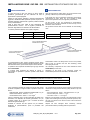
Generalmente le righe GVS vengono montate su presse
piegatrici sincronizzate, in posizione verticale. Qualora le righe
venissero utilizzate in altre applicazioni e montate in posizione
orizzontale (longitudinale o trasversale), attenersi alle indicazioni
riportate nel presente manuale.
Scegliere per l’ancoraggio del portariga il lato più accessibile,
riparato e prossimo alle guide di scorrimento della macchina da
equipaggiare.
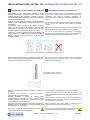
La guarnizione in gomma (labbra) per la protezione del reticolo
interno (GVS 200) o della banda magnetica (GVS 215) deve
essere sempre rivolta dalla parte opposta rispetto alla zona
operativa (si vedano le posizioni di montaggio consigliate).
L’aggiunta di un carter (soprattutto per gli assi particolarmente
esposti) costituisce un valido riparo dalla caduta accidentale di
attrezzi o lavorati oltre che un’ulteriore protezione dalle
infiltrazioni di liquidi.
GVS scales are generally used on synchronized press brakes
and mounted in vertical position. If the scales are used in other
applications and mounted horizontally (longitudinal or
transversal), please follow the indications provided in this
manual.
The scale should be mounted to be as accessible and protected
and as close to the machine’s slide guides as practically
possible.
Mount the scale with the sealing lips facing down or away from
the machining area (see recommended mounting positions).
The use of a sheet metal cover (especially for particularly
exposed axes) is recommended to prevent any damage from
falling tools or material and from infiltration of oils or fluids.
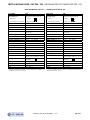
Evitare qualsiasi braccio di leva. Un adeguato orientamento del
giunto previene l’eventuale danneggiamento delle righe anche in
caso di discesa anomala del porta-punzone.
Any kind of lever arm must be avoided. A proper joint orientation
will prevent any scale damaging, even in case of anomalous
descent of the punch-holder.
Evitare la verniciatura delle superfici di appoggio e verificarne la
planarità.
E’ preferibile che a muoversi sia il portariga per evitare il
movimento del cavo di alimentazione.
Eventuali squadrette o sbracci di supporto vanno
opportunamente dimensionati e resi rigidi in maniera tale da
escludere qualsiasi loro flessione o vibrazione che possa
compromettere la precisione della riga.
Eseguire le connessioni in assenza di tensione di alimentazione
escludendo anche l’alimentazione di sicurezza (batterie) nelle
apparecchiature che la prevedono.
Non toccare i contatti del connettore del cavo per evitare
scariche elettrostatiche (ESD) sul dispositivo.
Avoid supporting surface painting and check their planarity.
To avoid and prevent contact of cable with any protrusion, the
reader head should remain stationary and the scale body should
be moved.
Spacer blocks or supporting arms should be adequately sized
and made rigid to exclude any flexion or vibration that could
compromise the scale’s accuracy.
Make connections when power supply is switched off and
batteries (when present) are excluded as well.
Do not touch the contacts of the cable’s connector in order
to avoid electrostatic discharges (ESD) on the device.
POSIZIONI DI MONTAGGIO CONSIGLIATE / RECOMMENDED MOUNTING POSITIONS
ORIENTAMENTO GIUNTO CONSIGLIATO
RECOMMENDED JOINT ORIENTATION

INSTALLAZIONE RIGHE GVS 200 - 215 INSTALLATION OF SCALES GVS 200 - 215
MT01_A50_A_GVS_200_215_GIVI_ENGITA rev. A MT0CV_GIVI_ENGITA(P) 19/03/10
Pag. 3/12
2
INSTALLAZIONE
2
INSTALLATION
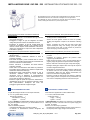
Fissare lateralmente il portariga con viti TCEI M6x20 (DIN 912).
Fissare il trasduttore al giunto a snodo mediante viti TCEI
M8x20, o al filo d’acciaio utilizzando viti TCEI M8x10.
Assicurarsi che il carrello non urti le estremità del portariga a fine
corsa (margine di sicurezza).
Sistemare il cavo e compiere manualmente la corsa totale per
accertarsi che nulla si opponga al libero scorrimento.
Fix the two scale ends with screws TCEI M6x20 (DIN 912).
Fix the transducer to the double-effect joint with screws M8x20,
or to the steel wire with screws TCEI M8x10.
Make sure the carriage does not hit the end caps during the
complete movement (safety margin).
Place the cable and manually cover the entire measuring length
to make sure that both the scale and the cable are able to move
without interferences.
Le righe GVS 200 e GVS 215 vengono fornite di serie con
adattatore GV-PB, che garantisce la compatibilità meccanica
con la riga PBS-HR.
GV-PB adapter is provided with each scale GVS 200 and
GVS 215, to guarantee the mechanical compatibility with
PBS-HR scale.
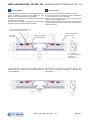
ML = CORSA UTILE /
ML = MEASURING LENGTH
QUOTE IN mm /
DIMENSIONS IN mm
MARGINE DI SICUREZZA
SAFETY MARGI
N
INDICI DI RIFERIMENTO
REFERENCE INDEXES
FINE CORSA
LIMIT SWITC
H
BARRA DI ATTIVAZIONE ZERO MAGNETO SET
A
CTIVATION BAR ZERO MAGNETO SET

INSTALLAZIONE RIGHE GVS 200 - 215 INSTALLATION OF SCALES GVS 200 - 215
MT01_A50_A_GVS_200_215_GIVI_ENGITA rev. A MT0CV_GIVI_ENGITA(P) 19/03/10
Pag. 4/12
3
OPERAZIONI FINALI E PRECAUZIONI
3
FINAL OPERATIONS AND PRECAUTIONS
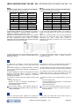
Verificare con un comparatore il corretto allineamento del
portariga e correggere ogni disallineamento.
Verificare il corretto collegamento e la continuità dello schermo
elettrico che deve essere collegato ad un nodo di messa a terra
avente minima impedenza (< 1 ).
Use a dial gauge to check the correct alignment of the scale
housing and correct any misalignment.
Check the correct connection and the continuity of the shield
which has to be connected to a grounding node with very low
impedance (< 1
).
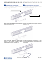
L’uscita del cavo dal trasduttore può essere facilmente
modificata. Allo scopo, svitare le due viti che bloccano il
coperchio (si veda il disegno sottostante), modificare
l’orientamento del cavo e serrare nuovamente le viti.
The output of the cable from the transducer can be easily
modified. To this purpose, loosen the screws that block the cover
(see the picture below), modify the cable orientation and tighten
again the screws.
PORTARIGA ALLINEATO 0,1 mm
ALIGNED SCALE HOUSING
0.1 mm

INSTALLAZIONE RIGHE GVS 200 - 215 INSTALLATION OF SCALES GVS 200 - 215
MT01_A50_A_GVS_200_215_GIVI_ENGITA rev. A MT0CV_GIVI_ENGITA(P) 19/03/10
Pag. 5/12
4
PRESSURIZZAZIONE
4
PRESSURIZATION
Le righe GVS 200 e GVS 215 offrono un ottimo grado di
protezione, generalmente più che sufficiente nel caso di
applicazione su presse piegatrici.
Qualora le righe fossero utilizzate in ambienti particolarmente
aggressivi, caratterizzati dalla presenza di polveri, liquidi, ecc., è
possibile migliorarne ulteriormente il grado di protezione tramite
la loro pressurizzazione.
Tutte le righe GVS sono infatti di serie predisposte alla
pressurizzazione, tramite i fori di ingresso posizionati su
entrambi i tappi laterali e su entrambi i lati del trasduttore.
Le classi di protezione ottenibili sono quindi le seguenti:
STANDARD PRESSURIZZATA
GVS 200 - OTTICA IP 54 IP 64
GVS 215 - MAGNETICA IP 64 IP 67
GVS 200 and GVS 215 scales offer a very good protection class,
generally sufficient for press brakes applications.
If the scales are used in particularly aggressive environments,
characterized by dusts, fluids, etc., it is possible to further
improve their protection class, through their pressurization.
All GVS scales, in fact, are predisposed to pressurization,
through the air inlet holes positioned on both end caps, and on
both sides of the transducer.
The protection classes that can be obtained are the following
ones:
STANDARD PRESSURIZED
GVS 200 - OPTICAL IP 54 IP 64
GVS 215 - MAGNETIC IP 64 IP 67
La pressurizzazione deve essere mantenuta sempre attiva.
Qualora questo non fosse possibile, attendere almeno 30 minuti
dall’ultima lavorazione, prima di interrompere il flusso dell’aria.
La portata di aria compressa necessaria per ogni riga varia dai
6 ai 9 normal l/min.
In funzione della lunghezza del sistema di misura, si
raccomanda di rispettare le pressioni riportate nella tabella
sottostante.
L’aria compressa introdotta nel sistema di misura deve essere
purificata e rispettare le seguenti classi di qualità a norma ISO
8573-1.
- Particelle solide: Classe 1 dimensione impurità solide 0,1 μm
- Grado di essiccazione: Classe 4 +3 °C
- Concentrazione d’olio: Classe 1 0,01 mg/m
3
Inoltre, è necessario che il circuito pneumatico sia dotato di un
essiccatore e di dispositivi di controllo (pressostato, ecc.). Si
consiglia l’utilizzo di un sensore per il controllo del flusso
dell’aria all’ingresso della riga.
Sostituire le cartucce dei filtri quando non più efficienti;
disattivare la pressurizzazione, prima di procedere alla
sostituzione.
Pressurization needs to be always active. If this is not possible,
wait at least 30 minutes from the last machining, before
interrupting the air flow.
The necessary compressed air flow varies between 6 and 9
normal l/min per each scale.
Depending on the length of the measuring system, the
recommended pressures are described in the table below.
The compressed air introduced in the measuring system must be
cleaned and comply with the following quality classes as per ISO
8573-1.
- Solid contaminants: Class 1 solid particles size 0.1 μm
- Pressure dew point: Class 4
+3 °C
- Oil content: Class 1
0.01 mg/m
3
Moreover, the pneumatic circuit has to be endowed with a drying
system and controlling devices (sense pneumatic pressure, etc.).
The use of a sensor for the air flow control at the scale inlet is
recommended.
Replace the filter cartridges when necessary; interrupt
pressurization before proceeding with the replacement.
PRESSIONI CONSIGLIATE IN FUNZIONE DELLA LUNGHEZZA DEL SISTEMA DI MISURA
RECOMMENDED PRESSURES ACCORDING TO SCALE LENGTH
0 1000 mm
1000 2000
> 2000
0.5 0.6 bar
0.6 0.7 bar 0.8 0.9 bar
ATTACCO PRESSURIZZAZIONE
COMPRESSED AIR INLET
ATTACCO PRESSURIZZAZIONE
COMPRESSED AIR INLET
ATTACCO PRESSURIZZAZIONE
COMPRESSED AIR INLET

INSTALLAZIONE RIGHE GVS 200 - 215 INSTALLATION OF SCALES GVS 200 - 215
MT01_A50_A_GVS_200_215_GIVI_ENGITA rev. A MT0CV_GIVI_ENGITA(P) 19/03/10
Pag. 6/12
Come prevenire la formazione di condensa in assenza di
pressurizzazione:
- Pulire frequentemente le zone adiacenti alla riga, evitando
l’uso di aria compressa.
- Proteggere al meglio la riga dai refrigeranti ed evitare
ristagni di liquidi nella vasca di raccolta della macchina.
- Proteggere, se possibile, la riga dal contatto diretto dei
vapori che si sviluppano durante il ciclo produttivo (tramite
l’utilizzo di carter superiori chiusi lateralmente o di schermi
inferiori che impediscano al vapore che sale di depositarsi
sulle labbra in gomma).
How to prevent condensate, when pressurization is not active:
- Clean frequently the machine guides close to the scale,
avoiding the use of compressed air.
- Protect the scale against coolants as much as possible,
avoiding the stagnation of liquids in the machine’s collecting
tank.
- Protect, if possible, the scale from the direct contact with
vapours developed during the working cycle (with upper
covers closed on the side or lower screens to prevent the
vapour from laying on the sealing lips).
Possibili cause di una pressurizzazione inefficace e rimedi:
- Filtraggio e qualità dell’aria inadeguati. Attenersi alle
istruzioni fornite.
- Pressione dell’aria insufficiente. Attenersi ai valori di
pressione consigliati.
- Filtri intasati da liquidi o polveri. Utilizzare filtri con scarico
automatico o provvedere regolarmente allo svuotamento dei
bicchieri e sostituire le cartucce dei filtri.
- Rottura, ostruzione o strozzatura dei tubetti dell’aria.
Verificarne l’integrità.
- Cattivo stato di conservazione delle labbra di protezione.
Provvedere alla loro sostituzione e verificare il rispetto delle
tolleranze di allineamento della riga.
- Disattivazione della pressurizzazione durante le fasi di
lavorazione. Attendere almeno 30 minuti dall’ultima
lavorazione prima di disattivare la pressurizzazione.
Verificare che la riga, in assenza di pressurizzazione, non
sia immersa nei liquidi che ristagnano.
- Presenza di getti di liquidi che colpiscono direttamente o
indirettamente la riga con una pressione superiore a quella
della pressurizzazione. Predisporre dei carter che
proteggano opportunamente la riga da tali getti.
Possible causes of an ineffective pressurization and remedies:
- Inadequate filtering and air quality. Respect the instructions
provided.
- Insufficient air pressure. Respect the pressure values
suggested by the Manufacturer.
- Filters blocked by liquids or dust. Use self-draining filters or
regularly empty the glasses and replace the filter cartridges.
- Broken, obstructed or blocked air pipes. Verify their integrity.
- Damaged sealing lips. Replace them and verify the respect of
the scale’s alignment tolerances.
- Deactivation of pressurization during machining. Wait at least
30 minutes from the last machining, before disconnecting
pressurization. Make sure that, without pressurization, the
scale is not immersed in stagnating liquids.
- Presence of liquid jets that hit the scale directly or indirectly,
with a higher pressure if compared to the pressurization one.
Use covers to adequately protect the scale from such jets.
5
COLLEGAMENTI ELETTRICI
5
ELECTRICAL CONNECTIONS
Le righe GVS vengono fornite con cavo 8 poli schermato,
= 6,1 mm, guaina esterna in PUR.
Sezione dei conduttori:
- alimentazioni: 0,35 mm
2
- segnali: 0,14 mm
2
In caso di prolunga, è indispensabile l’utilizzo di cavi schermati
con sezione superiore a 0,35 mm
2
per le alimentazioni e 0,14
mm
2
per i segnali.
Inoltre, è necessario garantire:
- il collegamento elettrico tra il corpo dei connettori;
- la tensione di alimentazione richiesta all’ingresso del
trasduttore.
GVS scales are supplied with a 8-wire shielded cable,
= 6.1 mm, PUR external sheath.
Conductors section:
- supply: 0.35 mm
2
- signals: 0.14 mm
2
If cable extensions are needed, it is necessary to use shielded
cables with a section of at least 0.35 mm
2
for power supply and
0.14 mm
2
for signals.
Moreover, it is necessary to guarantee:
- the electrical connection between the body of the connectors;
- the required power supply voltage to the transducer.
GIVI MISURE può fornire a richiesta unità di pressurizzazione che rispettino i valori di
qualità dell’aria richiesti e che consentano di collegare fino a tre righe ottiche.
GIVI MISURE can supply compressed air units that respect the required air quality
classes, allowing the connection of up to three optical scales.

INSTALLAZIONE RIGHE GVS 200 - 215 INSTALLATION OF SCALES GVS 200 - 215
MT01_A50_A_GVS_200_215_GIVI_ENGITA rev. A MT0CV_GIVI_ENGITA(P) 19/03/10
Pag. 7/12
NOTA
Rispettare un raggio minimo di curvatura del cavo di 80 mm.
Sono disponibili in uscita i seguenti segnali:
NOTE
The cable’s bending radius should not be lower than 80 mm.
The following output signals are available:
LINE DRIVER PUSH-PULL
COLORE
CONDUTTORE
LINE DRIVER PUSH-PULL
CONDUCTOR
COLOR
+ V + V
Rosso
+ V + V
Red
0 V 0 V
Blu
0 V 0 V
Blue
A B
Verde
A B
Green
A
NC
Arancio
A
NC
Orange
B A
Bianco
B A
White
B
NC
Azzurro
B
NC
Light-blue
I
0
I
0
Marrone
I
0
I
0
Brown
I
0
NC
Giallo
I
0
NC
Yellow
SCH SCH
Schermo
SCH SCH
Shield
Le righe hanno una configurazione di uscita LINE DRIVER. Se
l’apparecchiatura utilizzata non è predisposta per la lettura di
segnali LINE DRIVER, è necessario isolare singolarmente i
conduttori non utilizzati per evitare corto circuiti.
Rispettare una distanza minima di 200 mm tra il cavo e qualsiasi
dispositivo che possa essere fonte di disturbi elettromagnetici
(es. motori, elettrovalvole, inverter). Qualora si rilevassero
interferenze, intervenire direttamente sulla sorgente del disturbo
utilizzando allo scopo opportuni filtri EMC.
The scales are set up with a LINE DRIVER output. If the device
in use cannot read LINE DRIVER signals, it is necessary to
isolate the unused wires one by one in order to avoid short
circuits.
Make sure a minimum spacing of 200 mm exists between the
cable and any device that may cause electromagnetic
interferences (e.g. motors, solenoid valves, inverters). If
interferences are detected, act directly on the source of disturb
using EMC filters.
La riga è fornita di serie con un cavo adatto alla posa mobile di
lunghezza standard 0,5 m; lunghezze o tipologie differenti sono
disponibili su richiesta.
The scale is supplied with a standard 0,5 m-long cable, suitable
to continuous movements; longer or different cables are
available on request.
6
SELEZIONE DELL’INDICE DI RIFERIMENTO
6
REFERENCE INDEX SELECTION
Le righe GVS, in versione E, hanno indici di riferimento
posizionati con passo costante di 10 mm lungo tutta la corsa
utile.
Due etichette applicate sul portariga evidenziano le posizioni
degli indici più frequentemente utilizzate nell’applicazione su
presse piegatrici.
La barra di attivazione (in plastica rossa) identifica la posizione
dell’indice di riferimento attivato. La barra è mantenuta in
posizione da due grani che ne impediscono lo scorrimento
longitudinale nel portariga.
Per cambiare la posizione degli indici attivati, procedere come
segue:
- allentare entrambi i grani;
- spostare la barra di attivazione posizionandola in
corrispondenza dell’indice desiderato;
- serrare entrambi i grani.
GVS scales, in E version, have reference indexes placed at a
constant step of 10 mm, along the entire measuring length.
Two labels placed on the scale housing shows the positions of
the most used reference indexes, in the press brakes application.
The activation bar (red plastic bar) identifies the position of the
activated index. The bar is kept in its position by two fixing
dowels that prevent it from sliding along the scale housing.
To change the position of the activated indexes, proceed as
follows:
- loosen both fixing dowels;
- move the activation bar and position it in correspondence
to the desired index position;
- tighten both fixing dowels.
Non avvicinare magneti o corpi magnetici alla riga per
evitare l’attivazione accidentale di indici di riferimento in
posizioni indesiderate.
Do not place any external magnet close to the scale, to
avoid the accidental activation of reference indexes in
undesired positions.
7
OPZIONE: FINE CORSA
7
OPTION: LIMIT SWITCH
Qualora le righe GVS fossero acquistate con l’opzione Fine
Corsa, si raccomanda di prendere visione del manuale dedicato.
If GVS scales are ordered with the Limit Switch option, we
recommend to read the dedicated manual.
GVS

INSTALLAZIONE RIGHE GVS 200 - 215 INSTALLATION OF SCALES GVS 200 - 215
MT01_A50_A_GVS_200_215_GIVI_ENGITA rev. A MT0CV_GIVI_ENGITA(P) 19/03/10
Pag. 8/12
8
CARATTERISTICHE TECNICHE
8
TECHNICAL FEATURES
RIGA OTTICA GVS 200 – OPTICAL SCALE GVS 200
Cod. GVS 200
Supporto di misura
riga in vetro
Passo del reticolo
20 μm
Coeff. di dilatazione termica lineare
8 x 10
-6
C
-1
Indici di riferimento (I
0
)
E = selezionabili (ogni 10 mm)
C = a passo codificato
Risoluzione
10 - 5 - 1 - 0,5 - 0,1 μm
Classe di accuratezza
2,5 μm versione standard
1 μm versione high-accuracy
Corsa utile ML in mm
170, 220, 270, 320, 370, 420, 470, 520,
570, 620, 720, …
Velocità massima di traslazione
120 m/min *
Accelerazione massima
30 m/s
2
Resistenza all’avanzamento
1,5 N
Resistenza a vibrazioni (EN 60068-2-6)
100 m/s
2
[55 2 000 Hz]
Resistenza agli urti (EN 60068-2-27)
150 m/s
2
[11 ms]
Grado di protezione (EN 60529)
IP 54 standard IP 64 pressurizzata **
Temperatura di esercizio
0 C 50 C
Temperatura di stoccaggio
-20 C 70 C
Umidità relativa
20% 80% (non condensata)
Scorrimento carrello
su cuscinetti a sfere
Alimentazione
5 Vdc ± 5% oppure 10 ÷ 28 Vdc ± 5%
Assorbimento
140 mA
MAX
(con R= 120 ) 5 Vdc
100 mA
MAX
(con R= 1200 ) 10 ÷ 28 Vdc
Segnali d’uscita A, B e I
0
LINE DRIVER
PUSH-PULL
Lunghezza massima del cavo
25 m
***
Collegamenti elettrici
vedi tabella relativa
Protezioni elettriche
inversione di polarità e cortocircuiti
Peso
900 g + 1850 g/m
Cod. GVS 200
Measuring support
glass scale
Grating pitch
20 μm
Thermal expansion coefficient
8 x 10
-6
C
-1
Reference indexes (I
0
)
E = selectable (every 10 mm)
C = coded distance
Resolution
10 - 5 - 1 - 0.5 - 0.1 μm
Accuracy grade
2.5 μm standard version
1 μm high-accuracy version
Measuring length ML in mm
170, 220, 270, 320, 370, 420, 470, 520,
570, 620, 720, …
Max. traversing speed
120 m/min *
Max. acceleration
30 m/s
2
Required moving force
1.5 N
Vibration resistance (EN 60068-2-6)
100 m/s
2
[55
2 000 Hz]
Shock resistance (EN 60068-2-27)
150 m/s
2
[11 ms]
Protection class (EN 60529)
IP 54 standard IP 64 pressurized **
Operating temperature
0
C
50
C
Storage temperature
-20
C
70
C
Relative humidity
20%
80% (not condensed)
Carriage sliding
by ball bearings
Power supply
5 Vdc ± 5% or 10 ÷ 28 Vdc ± 5%
Current consumption
140 mA
MAX
(with R= 120
) 5 Vdc
100 mA
MAX
(with R= 1200
) 10 ÷ 28 Vdc
A, B and I
0
output signals
LINE DRIVER
PUSH-PULL
Max. cable length
25 m ***
Electrical connections
see related table
Electrical protections
inversion of polarity and short circuits
Weight
900 g + 1850 g/m
* Con risoluzione 0,1 μm, la velocità massima di traslazione si riduce a 40 m/min.
** Predisposizione alla pressurizzazione su richiesta.
*** Garantendo la tensione di alimentazione richiesta all’ingresso del trasduttore, la
lunghezza massima può arrivare a 100 m.
* With a 0.1 resolution, the maximum traversing speed becomes 40 m/min.
** Pressurization set up on request.
*** Ensuring the required power supply voltage to the transducer, the maximum cable
length can be extended to 100 m.
P
P

INSTALLAZIONE RIGHE GVS 200 - 215 INSTALLATION OF SCALES GVS 200 - 215
MT01_A50_A_GVS_200_215_GIVI_ENGITA rev. A MT0CV_GIVI_ENGITA(P) 19/03/10
Pag. 9/12
RIGA MAGNETICA GVS 215 – MAGNETIC SCALE GVS 215
Cod. GVS 215
Supporto di misura
plastoferrite su nastro in acciaio inox
Passo polare
2+2 mm
Coeff. di dilatazione termica lineare
10,6 x 10
-6
C
-1
Indici di riferimento (I
0
)
E = selezionabili (ogni 10 mm)
Risoluzione
50 - 25 - 10 - 5 - 1 μm
Ripetibilità
1 incremento
Classe di accuratezza
15 μm
Corsa utile ML in mm
170, 220, 270, 320, 370, 420, 470, 520,
570, 620, 720, …
Velocità massima di traslazione
120 m/min
Accelerazione massima
30 m/s
2
Resistenza all’avanzamento
1,5 N
Resistenza a vibrazioni (EN 60068-2-6)
100 m/s
2
[55 2 000 Hz]
Resistenza agli urti (EN 60068-2-27)
150 m/s
2
[11 ms]
Grado di protezione (EN 60529)
IP 64 standard IP 67 a richiesta
Temperatura di esercizio
0 C 50 C
Temperatura di stoccaggio
-20 C 70 C
Umidità relativa
20% 80% (non condensata)
Scorrimento carrello
senza contatto
Alimentazione
5 Vdc ± 5% oppure 10 ÷ 28 Vdc ± 5%
Assorbimento
140 mA
MAX
(con R= 120 ) 5 Vdc
100 mA
MAX
(con R= 1200 ) 10 ÷ 28 Vdc
Segnali d’uscita A, B e I
0
LINE DRIVER
PUSH-PULL
Lunghezza massima del cavo
25 m
*
Collegamenti elettrici
vedi tabella relativa
Protezioni elettriche
inversione di polarità e cortocircuiti
Peso
900 g + 1850 g/m
Cod. GVS 215
Measuring support
plastoferrite on stainless steel tape
Pole pitch
2+2 mm
Thermal expansion coefficient
10.6 x 10
-6
C
-1
Reference indexes (I
0
)
E = selectable (every 10 mm)
Resolution
50 - 25 - 10 - 5 - 1 μm
Repeatability
1 increment
Accuracy grade
15 μm
Measuring length ML in mm
170, 220, 270, 320, 370, 420, 470, 520,
570, 620, 720, …
Max. traversing speed
120 m/min
Max. acceleration
30 m/s
2
Required moving force
1.5 N
Vibration resistance (EN 60068-2-6)
100 m/s
2
[55
2 000 Hz]
Shock resistance (EN 60068-2-27)
150 m/s
2
[11 ms]
Protection class (EN 60529)
IP 64 standard IP 67 on request
Operating temperature
0
C
50
C
Storage temperature
-20
C
70
C
Relative humidity
20%
80% (not condensed)
Carriage sliding
without contact
Power supply
5 Vdc ± 5% or 10 ÷ 28 Vdc ± 5%
Current consumption
140 mA
MAX
(with R= 120
) 5 Vdc
100 mA
MAX
(with R= 1200
) 10 ÷ 28 Vdc
A, B and I
0
output signals
LINE DRIVER
PUSH-PULL
Max. cable length
25 m *
Electrical connections
see related table
Electrical protections
inversion of polarity and short circuits
Weight
900 g + 1850 g/m
* Garantendo la tensione di alimentazione richiesta all’ingresso del trasduttore, la
lunghezza massima può arrivare a 100 m.
* Ensuring the required power supply voltage to the transducer, the maximum cable
length can be extended to 100 m.
P
P

INSTALLAZIONE RIGHE GVS 200 - 215 INSTALLATION OF SCALES GVS 200 - 215
MT01_A50_A_GVS_200_215_GIVI_ENGITA rev. A MT0CV_GIVI_ENGITA(P) 19/03/10
Pag. 10/12
9
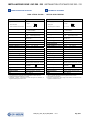
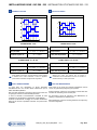
SEGNALI D’USCITA
9
OUTPUT SIGNALS
LINE DRIVER PUSH-PULL
ALIMENTAZIONE 5 Vdc
POWER SUPPLY 5 Vdc
Segnali d’uscita
LINE DRIVER
Output signals
LINE DRIVER
Carico per canale
R = 120 I
L
= 20 mA
MAX
Load per channel
R = 120 I
L
= 20 mA
MAX
Sfasamento segnali A e B
90 5 elettrici
A and B phase displacement
90
5
electrical
ALIMENTAZIONE 10 ÷ 28 Vdc
POWER SUPPLY 10 ÷ 28 Vdc
Segnali d’uscita
LINE DRIVER
Output signals
LINE DRIVER
Carico per canale
R = 1200 I
L
= 20 mA
MAX
Load per channel
R = 1200 I
L
= 20 mA
MAX
Sfasamento segnali A e B
90 5 elettrici
A and B phase displacement
90
5
electrical
Senza obbligo di preavviso, i prodotti potrebbero essere soggetti
a modifiche che la Casa Costruttrice si riserva di apportare
perché ritenute necessarie al miglioramento degli stessi.
Without prior notice, the products may be subject to
modifications that the Manufacturer reserves to introduce as
deemed necessary for their improvement.
10
USO E MANUTENZIONE
10
USE AND MAINTENANCE
Le righe GVS non necessitano di alcuna particolare
manutenzione ed il loro corretto utilizzo costituisce di per sé
fattore di stabilità qualitativa.
Nel corso delle lavorazioni rimuovere gli accumuli di trucioli che
si oppongono al libero scorrimento delle parti mobili.
In caso di anomalie di funzionamento consultare la Casa
Costruttrice per la riparazione o sostituzione di parti difettose.
Verificare le tolleranze di montaggio ed il corretto allineamento
della riga al termine di qualsiasi intervento che possa averlo
modificato.
GVS scales do not require any particular maintenance and the
correct use guarantees quality and good operation.
During machining, remove any accumulation of swarfs that does
not allow the free sliding of the movable parts.
Any discrepancy should be reported to the Manufacturer for
repairing or replacement of defective parts.
After maintenance, verify the mounting tolerances and adjust any
eventual misalignment.
90°
A
B
I
0
180° 270°
360°
A
B
I
0
90°
A
B
I
0
180° 270° 360°

INSTALLAZIONE RIGHE GVS 200 - 215 INSTALLATION OF SCALES GVS 200 - 215
MT01_A50_A_GVS_200_215_GIVI_ENGITA rev. A MT0CV_GIVI_ENGITA(P) 19/03/10
Pag. 11/12
11
TERMINI DI GARANZIA
11
WARRANTY TERMS
Le righe GVS 200 e GVS 215 sono garantite esenti da difetti di
fabbricazione per un periodo di ventiquattro mesi dalla data di
acquisto. L’eventuale riparazione dovrà essere effettuata presso
la Casa Costruttrice e il Cliente sarà tenuto a provvedere alla
consegna del prodotto presso la stessa.
L’inosservanza delle istruzioni e tolleranze di montaggio
determina il decadimento dei termini di garanzia ed esonera la
Casa Costruttrice dal rispondere dei malfunzionamenti causati
da installazioni non conformi.
La Casa Costruttrice non sarà tenuta a riparare e/o sostituire in
garanzia tutte le parti che dovessero risultare difettose a causa
di negligenza o trascuratezza nell’uso, di errata installazione o
manutenzione, di manutenzioni operate da personale non
autorizzato, di danni derivanti dal trasporto, ovvero di
circostanze che non è possibile far risalire a difetti di
fabbricazione dell’apparecchio.
La garanzia è altresì esclusa qualora vengano cancellati o
alterati i numeri di matricola o i dati identificativi del prodotto, e
qualora vengano apportate modifiche senza il consenso scritto
della Casa Costruttrice.
La Casa Costruttrice declina ogni responsabilità per eventuali
danni a cose o persone derivanti dall’utilizzo del prodotto,
inclusa, senza limitazione, qualsiasi perdita di guadagno ed ogni
altra perdita anche indiretta o accidentale.
GVS 200 and GVS 215 scales are guaranteed against
manufacturing faults for a period of twenty-four months from the
date of purchase. Any repair must take place at the
Manufacturer’s premises and the Customer shall arrange the
delivery of the product, at its own risk and expense.
The Manufacturer is released from any claim against damages
due to the non-observance of these instructions or mounting
tolerances which causes the annulment of the warranty terms.
The warranty does not provide for repairing and/or replacement
of those parts that have been damaged by negligence or misuse,
improper installation or maintenance, maintenance performed by
unauthorized personnel, transport or any other circumstance that
excludes a manufacturing fault of the product.
Similarly, the warranty does not apply if serial numbers or any
data identifying the product are cancelled or altered in any way,
and if product modifications are introduced without the written
authorization of the Manufacturer.
The Manufacturer declines any responsibility for damages to
people or properties deriving from the use of the product,
including any loss of profit or any other direct, indirect or
accidental loss.
12
SMALTIMENTO
12
DISPOSAL
Direttiva sui rifiuti di apparecchiature elettriche ed elettroniche (RAEE)
Direttiva 2002/96/CE del Parlamento Europeo
Disposal of waste electrical and electronic equipment (WEEE)
European Council Directive (2002/96/EC)
Il simbolo RAEE utilizzato per questo dispositivo indica che
quest'ultimo non può essere trattato come rifiuto domestico.
Lo smaltimento corretto di questo prodotto contribuirà a
proteggere l'ambiente.
Per maggiori informazioni sul riciclaggio di questo apparecchio,
rivolgersi all'ufficio competente del proprio ente locale, alla
società addetta allo smaltimento dei rifiuti domestici o al
rivenditore.
Questa informativa riguarda unicamente i clienti europei in
conformità con la Direttiva del Parlamento europeo n.
2002/96/CE. Per gli altri Paesi, fare riferimento alle Leggi locali.
The use of the WEEE Symbol indicates that this product may not be
treated as household waste.
If this product is disposed correctly, you will help to protect the
environment.
For more detailed information about the recycling of this product,
please contact your local authority, your household waste disposal
service provider or the retailer where you purchased the product.
This information regards only European customers, according to
2002/96/EC European Parliament Directive.
For other countries, please refer to local law requirements.

INSTALLAZIONE RIGHE GVS 200 - 215 INSTALLATION OF SCALES GVS 200 - 215
I NOSTRI PRODOTTI SONO VENDUTI ED ASSISTITI IN TUTTE LE NAZIONI INDUSTRIALIZZATE
OUR PRODUCTS ARE SOLD AND HAVE AFTER-SALE SERVICE IN ANY INDUSTRIALIZED COUNTRY
RIGHE OTTICHE
OPTICAL SCALES
SISTEMI MAGNETICI
MAGNETIC SYSTEMS
ENCODER ROTATIVI
ROTARY ENCODERS
VISUALIZZATORI
DIGITAL READOUTS
POSIZIONATORI
POSITION CONTROLLERS
GIVI MISURE S.r.l. A SOCIO UNICO Via Assunta, 57 - 20834 Nova Milanese (MB) - Italy
C.F. e Iscrizione al Reg. Imprese di Monza e Brianza n° 04355540156 - Cap. Soc. € 51.480,00 I.V.
Tel. +39 0362 366126 - Fax +39 0362 366876 - www.givimisure.it - sales@givimisure.it
-
 1
1
-
 2
2
-
 3
3
-
 4
4
-
 5
5
-
 6
6
-
 7
7
-
 8
8
-
 9
9
-
 10
10
-
 11
11
-
 12
12


Givi Misure GVS 200 Installation Manuals
- Tipo
- Installation Manuals
- Questo manuale è adatto anche per
in altre lingue
- English: Givi Misure GVS 200
Altri documenti
-
GYS PREMIUM INTEGRAL RESPIRATOR FFP3 Manuale del proprietario
-
-
-
Candy GVS 149THC3-01 Manuale utente
-
Canon IXUS 265 HS Manuale utente
-
Candy GVS4 127THB3/2-S Manuale utente
-
 Turbo EC++LS Manuale del proprietario
-
Eurotherm 306 6 channel multi point recorder Manuale del proprietario
-
Carel HUMISONIC UU0*R Manuale utente
-
