
Switch300
Control Box
Operating manual. . . . . . . . . . . . . . . . . . . . 7
Schaltbox
Bedienungsanleitung . . . . . . . . . . . . . . . . 15
Boîte de commande
Notice d’utilisation . . . . . . . . . . . . . . . . . . 23
Caja de distribución
Instrucciones de uso . . . . . . . . . . . . . . . . . 32
Caixa de distribuição
Manual de instruções . . . . . . . . . . . . . . . . 41
Scatola di comando
Istruzioni per l’uso. . . . . . . . . . . . . . . . . . . 50
Schakelbox
Gebruiksaanwijzing . . . . . . . . . . . . . . . . .60
Kontrolboks
Betjeningsvejledning . . . . . . . . . . . . . . . . 69
Kopplingsbox
Bruksanvisning . . . . . . . . . . . . . . . . . . . . . 77
Koblingsboks
Bruksanvisning . . . . . . . . . . . . . . . . . . . . . 85
Kytkinrasia
Käyttöohje . . . . . . . . . . . . . . . . . . . . . . . . . 93
Разветвительная коробка
Инструкция по эксплуатации . . . . . . . . .101
Rozgałęźnik
Instrukcja obsługi . . . . . . . . . . . . . . . . . . .110
Spínací box
Návod na obsluhu . . . . . . . . . . . . . . . . . .118
Spínací skříňka
Návod k obsluze. . . . . . . . . . . . . . . . . . . 126
Kapcsolódoboz
Használati utasítás . . . . . . . . . . . . . . . . . 134
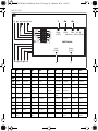
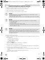
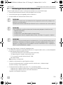
Right RCA DIN R L B
(CA3) (Monitor) (Mirror S/W)
SWITCH300
Left
(CA2)
Back
(CA1)
Left View S/W
Right Blink
Monitor
Trigger
Left Blink
11 – 32 V
GND
ACT-S/W
Right View S/W
B+
Back Gear
Back View S/W
EN
DE
FR
ES
PT
IT
NL
DA
SV
NO
FI
RU
PL
SK
CS
HU
DRIVING SUPPORT
PERFECTVIEW
SWITCH300-O-16S.book Seite 1 Freitag, 21. Oktober 2016 11:45 11

SWITCH300
2
1
45 6
23
1
2
SWITCH300-O-16S.book Seite 2 Freitag, 21. Oktober 2016 11:45 11

SWITCH300
3
Right RCA DIN R L B
(CA3) (Monitor) (Mirror S/W)
Left
(CA2)
Back
(CA1)
Left View S/W
Right Blink
Monitor
Trigger
Left Blink
GND
Right View S/W
B+
Back Gear
Back View S/W
SWITCH300
11 – 32 V
ACT-S/W
1
2
4
3
5
3
SWITCH300-O-16S.book Seite 3 Freitag, 21. Oktober 2016 11:45 11

SWITCH300
4
4
Right RCA DIN R L B
(CA3) (Monitor) (Mirror S/W)
SWITCH300
Left
(CA2)
Back
(CA1)
Left View S/W
Right Blink
Monitor
Trigger
Left Blink
11 – 32 V
GND
ACT-S/W
Right View S/W
B+
Back Gear
Back View S/W
1
2
5
12
3
Right RCA DIN R L B
(CA3) (Monitor) (Mirror S/W)
SWITCH300
Left
(CA2)
Back
(CA1)
Left View S/W
Right Blink
Monitor
Trigger
Left Blink
11 – 32 V
GND
ACT-S/W
Right View S/W
B+
Back Gear
Back View S/W
3
4
5
6
SWITCH300-O-16S.book Seite 4 Freitag, 21. Oktober 2016 11:45 11

SWITCH300
5
bl br ge gn gr or rt sw ws
EN
Blue Brown Yellow Green Grey Orange Red Black White
DE
BlauBraunGelbGrünGrauOrangeRot SchwarzWeiss
FR
Bleu Marron Jaune Vert Gris Orange Rouge Noir Blanc
ES
Azul Marrón Amarillo Verde Gris Naranja Rojo Negro Blanco
PT
Azul Castanho Ama-
relo
Verde Cin-
zento
Cor de
laranja
Ver-
melho
Preto Branco
IT
Blu Marrone Giallo Verde Grigio Aranci-
one
Rosso Nero Bianco
NL
Blauw Bruin Geel Groen Grijs Oranje Rood Zwart Wit
DA
Blå Brun Gul Grøn Grå Orange Rød Sort Hvid
SV
Blå Brun Gul Grön Grå Orange Röd Svart Vit
NO
Blå Brun Gul Grønn Grå Oransje Rød Svart Hvit
FI
Sini-
nen
Ruskea Keltai-
nen
Vihreä Harmaa Oranssi Punai-
nen
Musta Valkoi-
nen
gr ws sw rt/sw
2
34a
1
Right RCA DIN R L B
(CA3) (Monitor) (Mirror S/W)
Left
(CA2)
Back
(CA1)
Left View S/W
Right Blink
Monitor
Trigger
Left Blink
11 – 32 V
GND
Right View S/W
B+
Back Gear
Back View S/W
4b
rt
gn br ge or
bl
SWITCH300
ACT-S/W
6
SWITCH300-O-16S.book Seite 5 Freitag, 21. Oktober 2016 11:45 11

SWITCH300
6
RU
Синий Корич-
невый
Желтый Зеленый Серый Ора-
нжевый
Красный Черный Белый
PL
Nie-
bieski
Brązowy Żółty Zielony Szary Poma-
rańc-
zowy
Czer-
wony
Czarny Biały
SK
Modrá Hnedá Žltá Zelená Sivá Oran-
žová
Červená Čierna Biela
CS
Modrá Hněda Žlutá Zelená Šedá Oran-
žová
Červená Černá Bílá
HU
Kék Barna Sárga Zöld Szürke Narancs Piros Fekete Fehér
bl br ge gn gr or rt sw ws
SWITCH300-O-16S.book Seite 6 Freitag, 21. Oktober 2016 11:45 11

SWITCH300 Notes on using the manual
EN
7
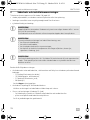
Please read this instruction manual carefully before first use, and store it in a safe place.
If you pass on the product to another person, hand over this instruction manual along
with it.
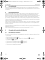
Contents
1 Notes on using the manual. . . . . . . . . . . . . . . . . . . . . . . . . . . . . . . . . . . . . . . . . . . . . . . . . . . .7
2 Safety and installation instructions . . . . . . . . . . . . . . . . . . . . . . . . . . . . . . . . . . . . . . . . . . . . . .8
3 Scope of delivery . . . . . . . . . . . . . . . . . . . . . . . . . . . . . . . . . . . . . . . . . . . . . . . . . . . . . . . . . . .9
4 Proper usage. . . . . . . . . . . . . . . . . . . . . . . . . . . . . . . . . . . . . . . . . . . . . . . . . . . . . . . . . . . . . . 10
5 Technical description . . . . . . . . . . . . . . . . . . . . . . . . . . . . . . . . . . . . . . . . . . . . . . . . . . . . . . . 10
6 Connecting the control box. . . . . . . . . . . . . . . . . . . . . . . . . . . . . . . . . . . . . . . . . . . . . . . . . . 11
7 Using the control box. . . . . . . . . . . . . . . . . . . . . . . . . . . . . . . . . . . . . . . . . . . . . . . . . . . . . . . 13
8 Guarantee . . . . . . . . . . . . . . . . . . . . . . . . . . . . . . . . . . . . . . . . . . . . . . . . . . . . . . . . . . . . . . . . 14
9 Disposal. . . . . . . . . . . . . . . . . . . . . . . . . . . . . . . . . . . . . . . . . . . . . . . . . . . . . . . . . . . . . . . . . . 14
10 Technical data. . . . . . . . . . . . . . . . . . . . . . . . . . . . . . . . . . . . . . . . . . . . . . . . . . . . . . . . . . . . . 14
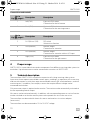
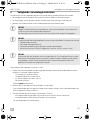
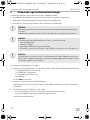
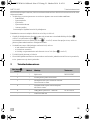
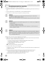
1 Notes on using the manual
A
I
NOTICE!
Failure to observe this instruction can cause material damage and impair the function
of the product.
NOTE
Supplementary information for operating the product.
SWITCH300-O-16S.book Seite 7 Freitag, 21. Oktober 2016 11:45 11

Safety and installation instructions SWITCH300
EN
8
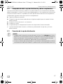
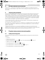
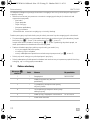
2 Safety and installation instructions
The manufacturer accepts no liability for damage in the following cases:
• Damage to the product resulting from mechanical influences and excess voltage
• Alterations to the product without express permission from the manufacturer
• Use for purposes other than those described in the operating manual
A
A
A
Please observe the following instructions:
• When working on the following supply lines, only use insulated cable lugs, plugs and tab
sleeves.
– 30 (direct supply from positive battery terminal)
–15 (connected positive terminal, behind the battery)
– 31 (return cable from the battery, earth)
– 58 (reversing light)
Do not use terminal strips.
• Use a crimping tool to connect the cables.
For permanent connections, you can solder the cable ends together and then insulate them.
• When connecting to supply cable 31 (earth), screw the cable
– to the vehicle's earth bolt with a cable lug and a gear disc or
– to the sheet-metal bodywork with a cable lug and a self-tapping screw.
Ensure that there is a good earth connection.
NOTICE!
To prevent short circuits, always disconnect the negative terminal of the electrical
system before working on the vehicle.
If the vehicle has an additional battery, its negative terminal should also be
disconnected.
NOTICE!
Inadequate supply cable connections could result in short circuits with the
consequence that:
• cable fires occur
• the airbag is triggered
• electronic control devices are damaged
• electric functions fail (indicators, brake light, horn, ignition, lights)
NOTICE!
Ensure that all lines are connected correctly. The control line may never be connected
to earth; doing so can damage the device. Make especially sure to insulate the bare
end of the control line when it is not in use and thus not connected.
SWITCH300-O-16S.book Seite 8 Freitag, 21. Oktober 2016 11:45 11

SWITCH300 Scope of delivery
EN
9
When the negative terminal of the battery is disconnected, all data stored in the volatile memory
will be lost.
• The following data must be set again, depending on the vehicle equipment options:
–radio code
– vehicle clock
–timer
– on-board computer
– seat position
You can find instructions for making these settings in the appropriate operating instructions.
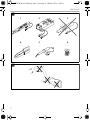
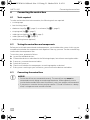
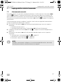
Observe the following instructions when working with electrical parts:
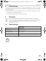
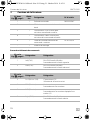
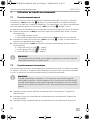
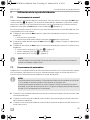
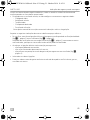
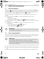
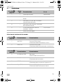
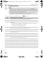
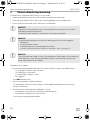
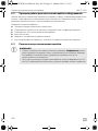
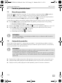
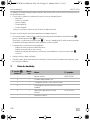
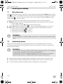
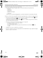
• When testing the voltage in electrical cables, only use a diode test lamp (fig. 1 1, page 2) or a
voltmeter (fig. 1 2, page 2).
Test lamps with an illuminant (fig. 1 3, page 2) consume voltages which are too high and can
damage the vehicle's electronic system.
• When making electrical connections, ensure that
– they are not kinked or twisted
– they do not rub on edges
– they are not laid in sharp edged ducts without protection (fig. 2, page 2).
• Insulate all connections.
• Secure the cables against mechanical wear with cable binders or insulating tape, for example
to existing cables.
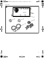
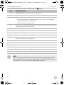
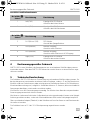
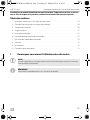
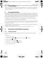
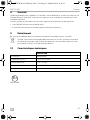
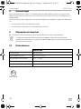
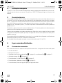
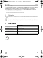
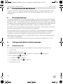
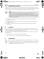
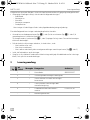
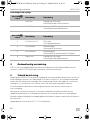
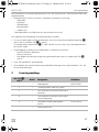
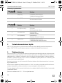
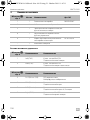
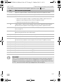
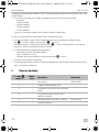
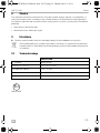
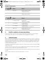
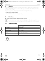
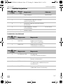
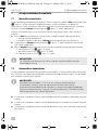
3Scope of delivery
No. in
fig. 3, page 3
Quan-
tity
Description Ref. no.
1 1 control box 9600000067
2 1 connection cable for vehicle electrics
3 1 three-stage switch for activating the
camera manually
4 1 two-stage switch for activating manual
operation
5 1 connecting cables for control box–
monitor
RV-502-M/M
– 1 installation material
SWITCH300-O-16S.book Seite 9 Freitag, 21. Oktober 2016 11:45 11

Proper usage SWITCH300
EN
10
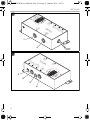
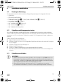
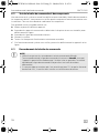
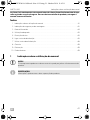
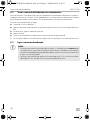
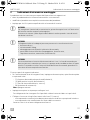
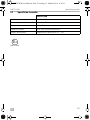
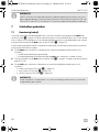
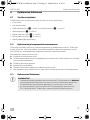
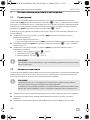
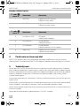
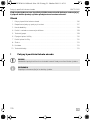
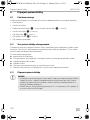
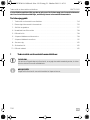
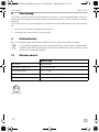
Connections and controls
4Proper usage
SWITCH300 is a control box that matches components from different reversing video systems to
each other. Up to three cameras can be connected to a monitor via SWITCH300.
5 Technical description
The control box SWITCH300 is used for the expansion of existing reversing video systems.
It possesses three separate controllable camera inputs, enabling e. g. operation with a reversing
and two side cameras or with three separate contollable cameras (for articulated buses, machine
monitoring etc.). In addition, for example, cameras that require different voltage can be
connected to each other.
Only one camera input is required on the monitor. The monitor can be automatically activated via
the corresponding control output.
All cameras can be activated manually. In addition, with corresponding cameras a mirror function
can be switched on so that the monitor picture corresponds to a view in the rear mirror.
The control box can be used with almost all cameras and monitors via various adapters
(accessories).
The control box can be connected to 12-V to 32-V DC voltage.
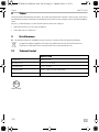
No. in
fig. 4, page 4
Description Description
1 Left (CA2) 6-pin mini DIN socket
Connection for the left camera
2 Back (CA1) 6-pin mini DIN socket
Connection for the reversing camera
No. in
fig. 5, page 4
Description Description
3 R L B (Mirror S/W) DIP switch
Select mirror function
4 DIN (Monitor) Monitor output
Connection for a monitor
5 RCA (Monitor) Monitor output
Connection for a monitor with an A/V input
6 Right (CA3) 6-pin mini DIN socket
Connection for the right camera
SWITCH300-O-16S.book Seite 10 Freitag, 21. Oktober 2016 11:45 11

SWITCH300 Connecting the control box
EN
11
6 Connecting the control box
6.1 Tools required
To make and test the electrical connection, the following tools are required:
• insulating tape
• heat shrinking sleeve
• diode test lamp (fig. 1 1, page 2) or voltmeter (fig. 1 2, page 2)
• crimping tool (fig. 1 4, page 2)
• soldering iron (optional) (fig. 1 5, page 2)
• solder (optional) (fig. 1 6, page 2)
• cable bushing sleeves (optional)
6.2 Testing the control box and components
Before you install and connect the desired components, you should test the system. In this way you
can determine whether the components work together in the way you want. You thus avoid having
to dismantle the components later.
To test the system, proceed as follows:
➤ Lay out the individual devices.
➤ Connect the devices as described in the following chapter, but without securing the cables.
➤ If necessary, connect the control cables.
➤ Switch the system on.
➤ Check to see whether the components are working together as desired.
✓ If the system is working to your satisfaction, you can secure the devices and cables.
6.3 Connecting the control box
A
NOTICE!
• Ensure that all lines are connected correctly. The control line may never be
connected to earth; doing so can damage the device. Make especially sure to
insulate the bare end of the control line when it is not in use and thus not connected.
• If you possess a monitor that may only be used for 12 V and 24-V electrics is being
used, a voltage converter must be installed.
SWITCH300-O-16S.book Seite 11 Freitag, 21. Oktober 2016 11:45 11

Connecting the control box SWITCH300
EN
12
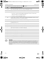
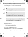
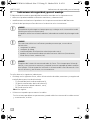
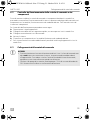
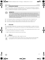
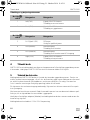
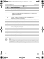
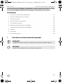
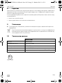
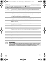
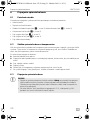
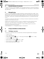
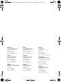
The circuit diagram for the control box can be found in fig. 6, page 5:
I
Pos. Connection name
rt/sw Red/black cable: connection to the two-pin switch
sw Black cable: Connection to earth (terminal 31)
ws White cable:
• Connection to the control cable of the three-pin switch for the right-hand
camera (connection to R switch-plug)
• Connection to the two-pin switch
gr Grey cable: Connection to the control line of the three-pin switch for the reverse
camera (connection to switch plug L)
rt Red cable: Connection to +12 V to +24 V (e. g. switched positive, terminal 15)
bl Blue cable: Connection to the monitor control line (standby/monitor on)
gn Green cable: Connection to the right indicator
br Brown cable: Connection to the left indicator light
ge Yellow cable: Connection to the control wire of the three-pin switch for the left
camera (connection to switch plug B)
or Orange cable: Connection to the reversing light
1 Camera connection 1
2 Camera connection 2
3 Camera connection 3
4a Output for reversing monitor (RCA)
4b Output for reversing monitor (DIN)
NOTE
SWITCH300 matches different reversing video components to each other, but no
video standards. For this reason camera and monitor must match (PAL with PAL and
NTSC with NTSC). Most LCD monitors support both standards.
SWITCH300-O-16S.book Seite 12 Freitag, 21. Oktober 2016 11:45 11

SWITCH300 Using the control box
EN
13
7 Using the control box
7.1 Manual operation
You can operate the control box manually. To do this, fit the two-stage switch (fig. 3 4, page 3)
supplied to a suitable place on the dashboard and connect it to the black/red and white cable.
With manual operation, you activate a particular camera by hand via the three-stage switch
(fig. 3 3, page 3) supplied.
In manual operation, a switch signal is sent via the blue cable which can activate the monitor.
➤ Place the two-stage switch in the required position to switch on the corresponding camera:
– I: manual operation is switched on
– 0: manual operation is switched off (the three-stage switch does not have a function)
➤ Connect the cables of the three-stage switch (fig. 3 3, page 3) according to the assignment
on page 12.
➤ Place the three-stage switch in the required position to switch on the corresponding camera:
– B: reversing camera (CA1) (fig. 6 1, page 5)
– L: left camera (CA2) (fig. 6 2, page 5)
– R right camera (CA3) (fig. 6 3, page 5)
I
7.2 Automatic operation
You can operate the control box in automatic mode. In the automatic mode the cameras switch on
or off automatically according to the control signal present. The monitor is activated automatically
via the control box.
I
➤ Connect the green line of the vehicle electrics connection cable to the right indicator light.
➤ Connect the brown line of the vehicle electrics connection cable to the left indicator light.
➤ Connect the orange line of the vehicle electrics connection cable to the reversing light.
NOTE
There is no signal on the control cable of the monitor during manual operation when
the switch is connected.
NOTE
During automatic operation a signal of +12 V is present on the control cable of the
monitor when one of the indicators or the reverse gear is activated.
The camera whose control cable is active is always activated in automatic mode
(priority to reverse gear). If the situation arises, a switch position deviating from this is
ignored.
SWITCH300-O-16S.book Seite 13 Freitag, 21. Oktober 2016 11:45 11

Guarantee SWITCH300
EN
14
8Guarantee
The statutory warranty period applies. If the product is defective, please contact the
manufacturer's branch in your country (see the back of the instruction manual for the addresses) or
your retailer.
For repair and guarantee processing, please include the following documents when you send in
the device:
• A copy of the receipt with purchasing date
• A reason for the claim or description of the fault
9Disposal
➤ Place the packaging material in the appropriate recycling waste bins wherever possible.
M
If you wish to finally dispose of the product, ask your local recycling centre or specialist
dealer for details about how to do this in accordance with the applicable disposal
regulations.
10 Technical data
SWITCH300
Ref. no.: 9600000067
Size (W x H x D): 130 x 30 x 57 mm
Operating voltage: 12 V – 32 Vg
Power consumption: max. 0.84 W (without camera)
Control inputs: positive 12 V – 24 V power signals
E4
10R-03 1855
SWITCH300-O-16S.book Seite 14 Freitag, 21. Oktober 2016 11:45 11

SWITCH300 Hinweise zur Benutzung der Anleitung
DE
15
Bitte lesen Sie diese Anleitung vor der Inbetriebnahme sorgfältig durch und bewahren
Sie sie auf. Geben Sie sie im Falle einer Weitergabe des Produktes an den Nutzer wei-
ter.
Inhaltsverzeichnis
1 Hinweise zur Benutzung der Anleitung. . . . . . . . . . . . . . . . . . . . . . . . . . . . . . . . . . . . . . . . . 15
2 Sicherheits- und Einbauhinweise. . . . . . . . . . . . . . . . . . . . . . . . . . . . . . . . . . . . . . . . . . . . . . 16
3 Lieferumfang . . . . . . . . . . . . . . . . . . . . . . . . . . . . . . . . . . . . . . . . . . . . . . . . . . . . . . . . . . . . . . 17
4 Bestimmungsgemäßer Gebrauch . . . . . . . . . . . . . . . . . . . . . . . . . . . . . . . . . . . . . . . . . . . . . 18
5 Technische Beschreibung . . . . . . . . . . . . . . . . . . . . . . . . . . . . . . . . . . . . . . . . . . . . . . . . . . . 18
6 Schaltbox anschließen . . . . . . . . . . . . . . . . . . . . . . . . . . . . . . . . . . . . . . . . . . . . . . . . . . . . . . 19
7 Schaltbox benutzen . . . . . . . . . . . . . . . . . . . . . . . . . . . . . . . . . . . . . . . . . . . . . . . . . . . . . . . . 21
8 Gewährleistung . . . . . . . . . . . . . . . . . . . . . . . . . . . . . . . . . . . . . . . . . . . . . . . . . . . . . . . . . . .22
9 Entsorgung . . . . . . . . . . . . . . . . . . . . . . . . . . . . . . . . . . . . . . . . . . . . . . . . . . . . . . . . . . . . . . .22
10 Technische Daten. . . . . . . . . . . . . . . . . . . . . . . . . . . . . . . . . . . . . . . . . . . . . . . . . . . . . . . . . .22
1 Hinweise zur Benutzung der Anleitung
A
I
ACHTUNG!
Nichtbeachtung kann zu Materialschäden führen und die Funktion des Produktes
beeinträchtigen.
HINWEIS
Ergänzende Informationen zur Bedienung des Produktes.
SWITCH300-O-16S.book Seite 15 Freitag, 21. Oktober 2016 11:45 11

Sicherheits- und Einbauhinweise SWITCH300
DE
16
2 Sicherheits- und Einbauhinweise
Der Hersteller übernimmt in folgenden Fällen keine Haftung für Schäden:
• Beschädigungen am Produkt durch mechanische Einflüsse und Überspannungen
• Veränderungen am Produkt ohne ausdrückliche Genehmigung vom Hersteller
• Verwendung für andere als die in der Anleitung beschriebenen Zwecke
A
A
A
Beachten Sie deshalb folgende Hinweise:
• Verwenden Sie bei Arbeiten an den folgenden Leitungen nur isolierte Kabelschuhe, Stecker
und Flachsteckhülsen.
– 30 (Eingang von Batterie Plus direkt),
– 15 (Geschaltetes Plus, hinter Batterie),
– 31 (Rückleitung ab Batterie, Masse),
– 58 (Rückfahrscheinwerfer).
Verwenden Sie keine Lüsterklemmen.
• Verwenden Sie eine Krimpzange zum Verbinden der Kabel.
Für Verbindungen, die nicht wieder gelöst werden sollen, können Sie die Kabelenden
miteinander verlöten und anschließend isolieren.
• Schrauben Sie das Kabel bei Anschlüssen an Leitung 31 (Masse)
– mit Kabelschuh und Zahnscheibe an eine fahrzeugeigene Masseschraube oder
– mit Kabelschuh und Blechschraube an das Karosserieblech.
Achten Sie auf eine gute Masseübertragung!
ACHTUNG!
Klemmen Sie wegen der Kurzschlussgefahr vor Arbeiten an der Fahrzeugelektrik
immer den Minuspol ab.
Bei Fahrzeugen mit Zusatzbatterie müssen Sie an dieser ebenfalls den Minuspol
abklemmen.
ACHTUNG!
Unzureichende Leitungsverbindungen können zur Folge haben, dass durch
Kurzschluss
• Kabelbrände entstehen,
• der Airbag ausgelöst wird,
• elektronische Steuerungseinrichtungen beschädigt werden,
• elektrische Funktionen ausfallen (Blinker, Bremslicht, Hupe, Zündung, Licht).
ACHTUNG!
Achten Sie auf einen korrekten Anschluss aller Leitungen. Es darf nie zu einer Verbin-
dung der Steuerleitung mit Masse kommen, da sonst ein Geräteschaden eintreten
kann. Isolieren Sie insbesondere das blanke Ende der Steuerleitung, wenn sie nicht
gebraucht und daher nicht angeschlossen wird!
SWITCH300-O-16S.book Seite 16 Freitag, 21. Oktober 2016 11:45 11

SWITCH300 Lieferumfang
DE
17
Beim Abklemmen des Minuspols der Batterie verlieren alle flüchtigen Speicher der Komfort-
elektronik ihre gespeicherten Daten.
• Folgende Daten müssen Sie je nach Fahrzeugausstattung neu einstellen:
–Radiocode
–Fahrzeuguhr
– Zeitschaltuhr
– Bordcomputer
– Sitzposition
Hinweise zur Einstellung finden Sie in der jeweiligen Bedienungsanleitung.
Beachten Sie folgende Hinweise bei der Arbeit an elektrischen Teilen:
• Benutzen Sie zum Prüfen der Spannung in elektrischen Leitungen nur eine Diodenprüflampe
(Abb. 1 1, Seite 2) oder ein Voltmeter (Abb. 1 2, Seite 2).
Prüflampen mit einem Leuchtkörper (Abb. 1 3, Seite 2) nehmen zu hohe Ströme auf,
wodurch die Fahrzeugelektronik beschädigt werden kann.
• Beachten Sie beim Verlegen der elektrischen Anschlüsse, dass diese
– nicht geknickt oder verdreht werden,
–nicht an Kanten scheuern,
– nicht ohne Schutz durch scharfkantige Durchführungen verlegt werden (Abb. 2, Seite 2).
• Isolieren Sie alle Verbindungen und Anschlüsse.
• Sichern Sie die Kabel gegen mechanische Beanspruchung durch Kabelbinder oder
Isolierband, z. B. an vorhandenen Leitungen.
3Lieferumfang
Nr. in Abb. 3,
Seite 3
Menge Bezeichnung Artikel-Nr.
1 1 Schaltbox 9600000067
21Anschlusskabel Bordnetz
3 1 Dreistufiger Schalter zur manuellen
Aktivierung der Kameras
4 1 Zweistufiger Schalter zur Aktivierung
der manuellen Bedienung
5 1 Verbindungskabel Schaltbox – Monitor RV-502-M/M
– 1 Montagematerial
SWITCH300-O-16S.book Seite 17 Freitag, 21. Oktober 2016 11:45 11

Bestimmungsgemäßer Gebrauch SWITCH300
DE
18
Anschlüsse und Bedienelemente
4 Bestimmungsgemäßer Gebrauch
SWITCH300 ist eine Schaltbox, die Komponenten aus verschiedenen Rückfahrvideosystemen
aneinander anpasst. Über den SWITCH300 können bis zu drei Kameras an einen Monitor ange-
schlossen werden.
5 Technische Beschreibung
Die Schaltbox SWITCH300 dient zur Erweiterung von vorhandenen Rückfahrvideosystemen. Sie
besitzt drei getrennt voneinander steuerbare Kamera-Eingänge, so dass z. B. ein Betrieb mit einer
Rückfahr- und zwei Seitenkameras oder mit drei getrennt steuerbaren Kameras (für Gelenkbusse,
Maschinenüberwachung usw.) möglich ist. Außerdem können z. B. Kameras, die unterschiedliche
Spannungen benötigen, miteinander verschaltet werden.
Am Monitor ist nur ein Kameraeingang notwendig. Der Monitor kann über den entsprechenden
Steuerausgang automatisch aktiviert werden.
Alle Kameras sind manuell aktivierbar. Außerdem kann mit entsprechenden Kameras eine Spiegel-
funktion geschaltet werden, so dass das Monitorbild einem Blick in den Rückspiegel entspricht.
Über verschiedene Adapter (Zubehör) ist die Schaltbox mit fast allen Kameras und Monitoren des
Herstellers einsetzbar.
Die Schaltbox kann an 12 V bis 32 V Gleichspannung angeschlossen werden.
Nr. in Abb. 4,
Seite 4
Bezeichnung Bezeichnung
1 Left (CA2) 6-polige Mini-DIN-Buchse
Anschluss der linken Kamera
2 Back (CA1) 6-polige Mini-DIN-Buchse
Anschluss der Rückfahrkamera
Nr. in Abb. 5,
Seite 4
Bezeichnung Bezeichnung
3 R L B (Mirror S/W) DIP-Schalter
Auswahl der Spiegelfunktion
4 DIN (Monitor) Monitor-Ausgang
Anschluss eines Monitors
5 RCA (Monitor) Monitor-Ausgang
Anschluss eines Monitor mit A/V-Eingang
6 Right (CA3) 6-polige Mini-DIN-Buchse
Anschluss der rechten Kamera
SWITCH300-O-16S.book Seite 18 Freitag, 21. Oktober 2016 11:45 11

SWITCH300 Schaltbox anschließen
DE
19
6 Schaltbox anschließen
6.1 Benötigtes Werkzeug
Für den elektrischen Anschluss und seine Überprüfung benötigen Sie folgende Hilfsmittel:
• Isolierband
• Wärmeschrumpfschlauch
• Diodenprüflampe (Abb. 1 1, Seite 2) oder Voltmeter (Abb. 1 2, Seite 2)
• Krimpzange (Abb. 1 4, Seite 2)
• Ggf. Lötkolben (Abb. 1 5, Seite 2)
• Ggf. Lötzinn (Abb. 1 6, Seite 2)
• Ggf. Kabeldurchführungstüllen
6.2 Schaltbox und Komponenten testen
Bevor Sie die Schaltbox und die gewünschten Komponenten fest montieren und verdrahten,
sollten Sie das System testen. Dadurch können Sie feststellen, ob die Komponenten zusammen
so arbeiten, wie Sie es wünschen. Dadurch vermeiden Sie, Komponenten wieder ausbauen zu
müssen.
Gehen Sie zum Testen wie folgt vor:
➤ Legen Sie die einzelnen Geräte aus.
➤ Schließen Sie die Geräte an wie im folgenden Kapitel beschrieben, aber ohne die Leitungen
fest zu verlegen.
➤ Schließen Sie ggf. die Steuerleitungen an.
➤ Schalten Sie das System ein.
➤ Testen Sie, ob die Komponenten wie zusammen gewünscht arbeiten.
✓ Wenn das System zu Ihrer Zufriedenheit arbeitet, können Sie die Geräte und Leitungen fest
verlegen.
6.3 Schaltbox anschließen
A
ACHTUNG!
• Achten Sie auf einen korrekten Anschluss aller Leitungen. Es darf nie zu einer Ver-
bindung der Steuerleitung mit Masse kommen, da sonst ein Geräteschaden ein-
treten kann. Isolieren Sie insbesondere das blanke Ende der Steuerleitung, wenn
sie nicht gebraucht und daher nicht angeschlossen wird!
• Wenn Sie einen Monitor besitzen, der nur für 12 V zugelassen ist, und ein
24-V-Bordnetz vorhanden ist, müssen Sie einen Spannungswandler installieren.
SWITCH300-O-16S.book Seite 19 Freitag, 21. Oktober 2016 11:45 11

Schaltbox anschließen SWITCH300
DE
20
Den Schaltplan für die Schaltbox finden Sie in Abb. 6, Seite 5:
I
Pos. Bezeichnung des Anschlusses
rt/sw Rot/Schwarzes Kabel: Anschluss an den zweipoligen Schalter
sw Schwarzes Kabel: Anschluss an Masse (Klemme 31)
ws Weißes Kabel:
• Anschluss an die Steuerleitung des dreipoligen Schalters für die rechte
Kamera (Anschluss an Schalter-Stecker R)
• Anschluss an den zweipoligen Schalter
gr Graues Kabel: Anschluss an die Steuerleitung des dreipoligen Schalters für die
Rückfahrkamera (Anschluss an Schalter-Stecker L)
rt Rotes Kabel: Anschluss an +12 V bis +24 V (z. B. geschaltetes Plus, Klemme 15)
bl Blaues Kabel: Anschluss an die Steuerleitung des Monitors
(Standby/Monitor an)
gn Grünes Kabel: Anschluss an den rechten Blinker
br Braunes Kabel: Anschluss an den linken Blinker
ge Gelbes Kabel: Anschluss an die Steuerleitung des dreipoligen Schalters für die
linke Kamera (Anschluss an Schalter-Stecker B)
or Orangefarbenes Kabel: Anschluss an die Rückfahrleuchte
1 Kamera-Anschluss 1
2 Kamera-Anschluss 2
3 Kamera-Anschluss 3
4a Ausgang für Rückfahrmonitor (Cinch)
4b Ausgang für Rückfahrmonitor (DIN)
HINWEIS
Der SWITCH300 passt verschiedene Rückfahrvideo-Komponenten aneinander an,
aber keine Videostandards. Daher müssen Kamera und Monitor zueinander passen
(PAL mit PAL und NTSC mit NTSC). Die meisten LCD-Monitore unterstützen beide
Standards.
SWITCH300-O-16S.book Seite 20 Freitag, 21. Oktober 2016 11:45 11
La pagina si sta caricando...
La pagina si sta caricando...
La pagina si sta caricando...
La pagina si sta caricando...
La pagina si sta caricando...
La pagina si sta caricando...
La pagina si sta caricando...
La pagina si sta caricando...
La pagina si sta caricando...
La pagina si sta caricando...
La pagina si sta caricando...
La pagina si sta caricando...
La pagina si sta caricando...
La pagina si sta caricando...
La pagina si sta caricando...
La pagina si sta caricando...
La pagina si sta caricando...
La pagina si sta caricando...
La pagina si sta caricando...
La pagina si sta caricando...
La pagina si sta caricando...
La pagina si sta caricando...
La pagina si sta caricando...
La pagina si sta caricando...
La pagina si sta caricando...
La pagina si sta caricando...
La pagina si sta caricando...
La pagina si sta caricando...
La pagina si sta caricando...
La pagina si sta caricando...
La pagina si sta caricando...
La pagina si sta caricando...
La pagina si sta caricando...
La pagina si sta caricando...
La pagina si sta caricando...
La pagina si sta caricando...
La pagina si sta caricando...
La pagina si sta caricando...
La pagina si sta caricando...
La pagina si sta caricando...
La pagina si sta caricando...
La pagina si sta caricando...
La pagina si sta caricando...
La pagina si sta caricando...
La pagina si sta caricando...
La pagina si sta caricando...
La pagina si sta caricando...
La pagina si sta caricando...
La pagina si sta caricando...
La pagina si sta caricando...
La pagina si sta caricando...
La pagina si sta caricando...
La pagina si sta caricando...
La pagina si sta caricando...
La pagina si sta caricando...
La pagina si sta caricando...
La pagina si sta caricando...
La pagina si sta caricando...
La pagina si sta caricando...
La pagina si sta caricando...
La pagina si sta caricando...
La pagina si sta caricando...
La pagina si sta caricando...
La pagina si sta caricando...
La pagina si sta caricando...
La pagina si sta caricando...
La pagina si sta caricando...
La pagina si sta caricando...
La pagina si sta caricando...
La pagina si sta caricando...
La pagina si sta caricando...
La pagina si sta caricando...
La pagina si sta caricando...
La pagina si sta caricando...
La pagina si sta caricando...
La pagina si sta caricando...
La pagina si sta caricando...
La pagina si sta caricando...
La pagina si sta caricando...
La pagina si sta caricando...
La pagina si sta caricando...
La pagina si sta caricando...
La pagina si sta caricando...
La pagina si sta caricando...
La pagina si sta caricando...
La pagina si sta caricando...
La pagina si sta caricando...
La pagina si sta caricando...
La pagina si sta caricando...
La pagina si sta caricando...
La pagina si sta caricando...
La pagina si sta caricando...
La pagina si sta caricando...
La pagina si sta caricando...
La pagina si sta caricando...
La pagina si sta caricando...
La pagina si sta caricando...
La pagina si sta caricando...
La pagina si sta caricando...
La pagina si sta caricando...
La pagina si sta caricando...
La pagina si sta caricando...
La pagina si sta caricando...
La pagina si sta caricando...
La pagina si sta caricando...
La pagina si sta caricando...
La pagina si sta caricando...
La pagina si sta caricando...
La pagina si sta caricando...
La pagina si sta caricando...
La pagina si sta caricando...
La pagina si sta caricando...
La pagina si sta caricando...
La pagina si sta caricando...
La pagina si sta caricando...
La pagina si sta caricando...
La pagina si sta caricando...
La pagina si sta caricando...
La pagina si sta caricando...
La pagina si sta caricando...
La pagina si sta caricando...
La pagina si sta caricando...
La pagina si sta caricando...
La pagina si sta caricando...
-
 1
1
-
 2
2
-
 3
3
-
 4
4
-
 5
5
-
 6
6
-
 7
7
-
 8
8
-
 9
9
-
 10
10
-
 11
11
-
 12
12
-
 13
13
-
 14
14
-
 15
15
-
 16
16
-
 17
17
-
 18
18
-
 19
19
-
 20
20
-
 21
21
-
 22
22
-
 23
23
-
 24
24
-
 25
25
-
 26
26
-
 27
27
-
 28
28
-
 29
29
-
 30
30
-
 31
31
-
 32
32
-
 33
33
-
 34
34
-
 35
35
-
 36
36
-
 37
37
-
 38
38
-
 39
39
-
 40
40
-
 41
41
-
 42
42
-
 43
43
-
 44
44
-
 45
45
-
 46
46
-
 47
47
-
 48
48
-
 49
49
-
 50
50
-
 51
51
-
 52
52
-
 53
53
-
 54
54
-
 55
55
-
 56
56
-
 57
57
-
 58
58
-
 59
59
-
 60
60
-
 61
61
-
 62
62
-
 63
63
-
 64
64
-
 65
65
-
 66
66
-
 67
67
-
 68
68
-
 69
69
-
 70
70
-
 71
71
-
 72
72
-
 73
73
-
 74
74
-
 75
75
-
 76
76
-
 77
77
-
 78
78
-
 79
79
-
 80
80
-
 81
81
-
 82
82
-
 83
83
-
 84
84
-
 85
85
-
 86
86
-
 87
87
-
 88
88
-
 89
89
-
 90
90
-
 91
91
-
 92
92
-
 93
93
-
 94
94
-
 95
95
-
 96
96
-
 97
97
-
 98
98
-
 99
99
-
 100
100
-
 101
101
-
 102
102
-
 103
103
-
 104
104
-
 105
105
-
 106
106
-
 107
107
-
 108
108
-
 109
109
-
 110
110
-
 111
111
-
 112
112
-
 113
113
-
 114
114
-
 115
115
-
 116
116
-
 117
117
-
 118
118
-
 119
119
-
 120
120
-
 121
121
-
 122
122
-
 123
123
-
 124
124
-
 125
125
-
 126
126
-
 127
127
-
 128
128
-
 129
129
-
 130
130
-
 131
131
-
 132
132
-
 133
133
-
 134
134
-
 135
135
-
 136
136
-
 137
137
-
 138
138
-
 139
139
-
 140
140
-
 141
141
-
 142
142
-
 143
143
-
 144
144


Dometic Switch 300 Istruzioni per l'uso
- Tipo
- Istruzioni per l'uso
- Questo manuale è adatto anche per
in altre lingue
- français: Dometic Switch 300 Mode d'emploi
- español: Dometic Switch 300 Instrucciones de operación
- Deutsch: Dometic Switch 300 Bedienungsanleitung
- português: Dometic Switch 300 Instruções de operação
- slovenčina: Dometic Switch 300 Návod na používanie
- dansk: Dometic Switch 300 Betjeningsvejledning
Documenti correlati
-
Waeco Waeco RV-SWITCH-SV Istruzioni per l'uso
-
Dometic AMP100 Istruzioni per l'uso
-
-
-
-
-
-
-
-