
1/4
DESCRIZIONE GENERALE
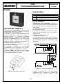
Il pulsante antincendio P445 è utilizzato per la
segnalazione manuale di allarme su impianti
antincendio di tipo convenzionale.
Il pulsante è di tipo a rottura: effettuando una
pressione sulla parte centrale del pulsante, il
frontale plastico si romperà, azionando
automaticamente l’interruttore di segnalazione
allarme. L’accensione del LED di colore rosso
indica lo stato di allarme. Per il ripristino
occorrerà aprire il pulsante ed effettuare la
sostituzione del frontale plastico.
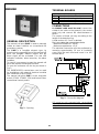
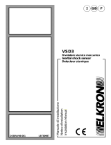
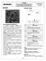
Per aprire il contenitore utilizzare la chiavetta
come illustrato dalla Fig. 1.
È possibile utilizzare la contro-base
80SB7410121 per installazioni con canaline
elettriche esterne con diametro fino a 20mm.
Il pulsante P445 è da utilizzarsi con le attuali
centrali convenzionali Elkron (C7000, C7000R,
C54) e quelle di prossimo sviluppo.
Fig. 1 – Apertura del contenitore
MORSETTIERA
M1 - Descrizione
IN+
Ingresso positivo linea rivelazione
IN-
Ingresso negativo linea rivelazione
OUT+
Uscita positivo linea rivelazione
OUT-
Uscita negativo linea rivelazione
COLLEGAMENTI
Utilizzare un cavo schermato: collegare lo
schermo del cavo solo alla massa della centrale
ed assicurarsi della sua continuità elettrica su
tutta la linea.
La sezione dei conduttori può variare in base
alla lunghezza del cavo.
Si consiglia un conduttore con sezione di 1,5 mm2.
Usare un cavo elettrico che non ecceda i
seguenti limiti:
Resistenza massima = 100 Ω
Capacità massima = 2 µF
Il collegamento elettrico deve essere effettuato
rimuovendo circa 10 mm di protezione isolante
dal conduttore principale inserendolo nella
morsettiera.
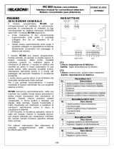
Fig. 2 – Schema di collegamento
Eseguire il ponticello JP1 solo con centrali
convenzionali che riconoscono i pulsanti dai
rivelatori posti sulla stessa linea.
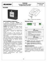
P445
Pulsante antincendio convenzionale a rottura
Conventional Frangible Manual Call Point
DS80SB35-001E
LBT80345
ITALIANO

2/4
TESTING (personale addestrato)
Prima di iniziare le operazioni di test,
comunicare all’autorità competente che il
sistema è temporaneamente fuori servizio a
causa della manutenzione in corso.
Per testare il pulsante, azionarlo e verificare la
condizione di allarme.
Al termine delle operazioni di test, riportare il
sistema nelle normali condizioni operative e
comunicare il ripristino alle autorità competenti.
CARATTERISTICHE TECNICHE
Tensione di
funzionamento
20 Vcc (-15%, +10%)
Assorbimento in
condizione di allarme
(JP1 aperto)
26 mA @ 20Vcc
Assorbimento in
condizione di allarme
(JP1 chiuso)
53 mA @ 20Vcc
LED indicatore
Rosso fisso:
stato di allarme
Temperatura di
funzionamento
-10 55°C ± 2°C
(14 131°F)
Umidità relativa
93 % ± 2%
non condensante
Temperatura di
immagazzinamento
-30 70 °C
(-22 158°F)
Condizione di allarme
Tipo A
Classe ambientale
Interno
Dimensioni
110x110x42 mm
Peso
100 g
Materiale contenitore
ABS V0
Conforme alla norma EN54-11: 2001/A1:2005
Pulsante antincendio a rottura
Mod. P445
Urmet S.p.A. 1293-CPD-0345
DoP n. 1293-CPR-0345
Ulteriori informazioni sono disponibili presso il costruttore.
10
1293

3/4
GENERAL DESCRIPTION
The manual call point P445 is used to manually
initiate an alarm condition on conventional fire
prevention systems.
The P445 is a frangible element type: by
pressing on the operating face of the manual call
point, the frangible element breaks and the
alarm signal will be activated. The red LED
indication indicates, when turned-on, the alarm
condition.
To reset it is necessary to open the manual call
point and replace the frangible element.
To open the enclosure use the key as shown in
Fig. 1.
The 80SB7410121 counter-base can be used
for installations with external electrical conduits
with a diameter of up to 20mm.
The manual call point P445 is to be used with
actual (C7000, C7000R, C54) and future Elkron
conventional control panels.
Fig. 1 – Opening
TERMINAL BOARDS
M1 - Description
IN+
Detection circuit positive input
IN-
Detection circuit negative input
OUT+
Detection circuit positive output
OUT-
Detection circuit negative output
CONNECTIONS
A shielded cable must be used: connect the
shield of the cable to the ground in the control
panel only and connect the shield between a
device.
The section of leads can vary according to the
length of the detection line.
A lead section of 1.5 mm2 is advised.
Don’t use cable that exceed these limits:
Maximum resistance = 100 Ω
Maximum capacitance = 2 µF
The electrical connection must be performed by
removing approximately 10 mm of insulating
cover from the main lead and insert it on the
terminal block.
Fig. 2 – Connection diagram
JP1 must be only executed with conventional
control panels that are able to recognize manual
call points from detectors on the same circuit.
ENGLISH

4/4
TESTING (trained personnel)
Before testing, notify to competent authority that
the system is temporarily out of service due to
maintenance operations.
To test the manual call point, open it, remove
the frangible element and move the switch for
simulate the frangible element breaks.
Verify the alarm condition.
At the end of testing operations, restore the
system to normal operation and notify the status
to the competent authorities.
TECHNICAL SPECIFICATIONS
Operating voltage
20 Vdc (-15%, +10%)
Power consumption in
alarm condition
(JP1 opened)
26 mA @ 20Vdc
Power consumption in
alarm condition
(JP1 closed)
53 mA @ 20Vdc
LED indicator
Red steady:
alarm condition
Operating temperature
-10 55°C ± 2°C
(14 131°F)
Relative humidity
93 % ± 2%
non condensing
Storage/shipping
temperature
-30 70 °C
(-22 158°F)
Alarm condition
Type A
Environmental class
Inside
Dimensions
110x110x42 mm
Weight
140 g
Enclosure material
ABS V0
In compliance with EN54-11: 2001/A1:2005
Frangible Manual Call Point
Mod. P445
Urmet S.p.A. 1293-CPD-0345
DoP n. 1293-CPR-0345
Further information are available to the manufacturer.
10
1293
ITALIANO
DIRETTIVA 2012/19/UE DEL PARLAMENTO EUROPEO E DEL CONSIGLIO del 4 luglio 2012 sui rifiuti di apparecchiature
elettriche ed elettroniche (RAEE)
Il simbolo del cassonetto barrato riportato sull’apparecchiatura o sulla sua confezione indica che il prodotto alla fine della propria vita utile
deve essere raccolto separatamente dagli altri rifiuti. L’utente dovrà, pertanto, conferire l’apparecchiatura giunta a fine vita agli idonei
centri comunali di raccolta differenziata dei rifiuti elettrotecnici ed elettronici. In alternativa alla gestione autonoma è possibile consegnare
l’apparecchiatura che si desidera smaltire al rivenditore, al momento dell’acquisto di una nuova apparecchiatura di tipo equivalente.
Presso i rivenditori di prodotti elettronici con superficie di vendita di almeno 400 m2 è inoltre possibile consegnare gratuitamente, senza
obbligo di acquisto, i prodotti elettronici da smaltire con dimensione massima inferiore a 25 cm. L’adeguata raccolta differenziata per
l’avvio successivo dell’apparecchiatura dismessa al riciclaggio, al trattamento e allo smaltimento ambientalmente compatibile contribuisce
ad evitare possibili effetti negativi sull’ambiente e sulla salute e favorisce il reimpiego e/o riciclo dei materiali di cui è composta
l’apparecchiatura.
ENGLISH DIRECTIVE 2012/19/EU OF THE EUROPEAN PARLIAMENT AND OF THE COUNCIL of 4 July 2012 on waste electrical and
electronic equipment (WEEE)
The symbol of the crossed-out wheeled bin on the product or on its packaging indicates that this product must not be disposed of with
your other household waste.
Instead, it is your responsibility to dispose of your waste equipment by handing it over to a designated collection point for the recycling of
waste electrical and electronic equipment.
The separate collection and recycling of your waste equipment at the time of disposal will help to conserve natural resources and ensure
that it is recycled in a manner that protects human health and the environment.
For more information about where you can drop off your waste equipment for recycling, please contact your local city office, your
household waste disposal service or the shop where you purchased the product.
ELKRON
Tel. +39 011.3986711 - Fax +39 011.3986703
Milano:Tel. +39 02.334491- Fax +39 02.33449213
www.elkron.com – mail to: [email protected]
ELKRON è un marchio commerciale di URMET S.p.A.
ELKRON is a trademark of URMET S.p.A.
Via Bologna, 188/C - 10154 Torino (TO) – Italy
www.urmet.com MADE IN ITALY
-
 1
1
-
 2
2
-
 3
3
-
 4
4


in altre lingue
- English: Elkron P445 Installation guide
Documenti correlati
-
 Elkron FMR500 Guida d'installazione
-
 Elkron VSD3 Guida d'installazione
-
 Elkron MC500 Guida d'installazione
-
 Elkron IOM500 Guida d'installazione
-
 Elkron SD500LI Guida d'installazione
-
 Elkron FLR100 Guida d'installazione
-
 Elkron IO501 Guida d'installazione
-
 Elkron iO500 Guida d'installazione
-
 Elkron iTG500 Guida d'installazione
-
 Elkron FDTD500 Guida d'installazione


