Contura 310 & 310G Istruzioni per l'uso
- Categoria
- Stufa a legna
- Tipo
- Istruzioni per l'uso

310
310G
contura.eu

SE
FR
FI
DE
GB
IT
NO
DK
NL
Fakta 3
Installationsavstånd 4
Prestandadeklaration 5
EU-försäkran om överrenskommelse 6
Montering 39
Tiedot 27
Asennusetäisyys 28
Suoritustasoilmoitus 29
EU-vaatimustenmukaisuusvakuutus 30
Asennus 39
Données Techniques 15
Distances d’installation 16
Déclaration des performance 17
Déclaration de conformité UE 18
Montage 39
Fakta 11
Installasjonsavstand 12
Ytelseserklæring 13
EU-samsvarserklæring 14
Montering 39
Fakta 23
Installationsafstand 24
Præstationserklæring 25
EU-overensstemmelserklæring 26
Montering 39
Gegevens 35
Installatieafstand 36
Prestatieverklaring 37
EU-conformiteitsverklaring 38
Monteren 39
Fakten 7
Installationsabstände 8
Leistungsdeklaration 9
EU-Konformitätserklärun 10
Montage 39
Facts 19
Installation distances 20
Declaration of performance 21
EU Declaration of Conformity 22
Assembly 39
Dati Tecnici 31
Distanze di sicurrezza 32
Dichiarazione di prestazione 33
Dichiarazione di Conformità UE 34
Montaggio 39

GB
19
!
5-9 kW 850 mm 750 mm 375 mm 130 kg
Installation by authorised
technician
This manual contains instructions about how
the stoves must be assembled and installed.
To ensure the function and safety of the stove,
we recommend that the installation is carried
out by an authorised technician. Contact one
of our dealers who can recommend suitable
technicians.
Building application
These main instructions may give guidance
which would contravene national building
regulations. Please refer to supplementary
instructions or ask your local authority for
advice regarding building regulations.
Before installing a stove or erecting a chimney
it is necessary for you to make a building
application permission to your local authority.
The owner of the house is personally
responsible for ensuring compliance with the
mandatory safety requirements and must
have the installation approved by a qualified
inspector. Your local chimney sweep must
also be informed about the installation as this
will affect the routines for regular chimney-
sweeping services.
Structural support
Check that the wood joists are strong enough
to bear the weight of the stove and chimney.
The stove and chimney can usually be placed
on a normal wooden joist in a single occupancy
house if the total weight does not exceed
400 kg.
Hearth plate
Due to the risk of falling embers, a flammable
floor must be protected by a hearth plate. It
must extend 300 mm in front of the stove and
100 mm on each side of the stove, or have a
200 mm extension on each side of the opening.
The hearth plate can consist of natural stone,
concrete, metal plate or glass. A glass hearth
plate is available as an accessory for these
models.
Final inspection of the
installation
It is extremely important that the installation
is inspected by an authorised chimney sweep
before the stove is used. Also read the
”Lighting instructions”, before lighting for the
first time.
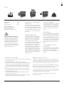
Nominal effect 7 kW
Efficiency 77%
Flue gas mass flow 5,9 g/s
Meets requirements of:
European standard EN-13240
NS 3058/3059 (Norway)
DEFRA, Smoke control areas (UK)
The stove becomes very hot
During operation, certain surfaces of the
stove become very hot and can cause
burn injury if touched. Be aware of the
strong heat radiated through the hatch
glass. Placing flammable material closer
than the safe distance indicated may
cause a fire. Pyre lighting can cause quick
gas ignition with the risk of damage to
property and personal injury.
Connection to chimney
• The stove must be connected to chimneys dimensioned for a minimum flue
gas temperature of 400°C.
• The external diameter of the connection sleeve is 150 mm.
• Normal chimney draw under nominal operation should be between 20-25
Pa close to the connector. The draft is affected both by the length and
area of the chimney, and by how well sealed it is. The recommended
minimum flue length is 3.5 m and its diameter should be Ø130 to Ø150
mm.
• A flue with sharp bends and horizontal routing reduces the draught in
the chimney. Maximum horizontal flue is 1 m, on the condition that the
vertical flue length is at least 5 m.
• It must be possible to sweep the full length of the flue and the soot
hatches must be easily accessible.
• Carefully check that the chimney is sealed and that there is no leakage
around soot hatches and flue connections. See page 40.
Supply of combustion air
When a stove is installed in a room, the demand for air supply to the room
increases. Air can be provided indirectly via a vent in the outer wall or via a
duct from the outside that is connected to the connector on the underneath
of the stove. The amount of air needed for combustion is 20 m3/h.
The connector for the combustion air has an external diameter of 65 mm.
When duct routing further than 1 m the pipe diameter must be increased to
100 mm and a correspondingly larger wall vent must be selected.
In hot areas, the duct should be insulated with 30 mm mineral wool with a
moisture inhibiting outer cover. It is also important to seal around the hole
in the wall (or floor) of the lead-in using sealant.
A 1 m length of condensation insulated ducting for combustion air is
available as an accessory.
Facts
Contura reserves the right to change dimensions and procedures described in these instructions
at any time without special notice. The current edition can be downloaded from www.contura.eu

GB
20
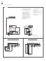
The minimum distance in front of
the stove opening to combustible
parts of the building or interior
decoration must be at least 1,4 m.
The dimension diagrams only
show the minimum permitted
installation distances for the
stove. When connecting to a steel
flue, also note the safety distance
requirements of the flue. The
safety distance between an un-
insulated flue and a combustible
part of the building should be at
least 450 mm.
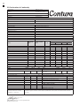
Installation distances
A = height from floor to chimney
connection upwards
B = height from floor to c/c chimney
connection rear
C = height from floor to air inlet
D = height from floor to lower edge
of hatch
E = height from floor to lower edge
of heat deflector
* If the stove is placed on a hearth plate made of glass for example (accessory), the height from the floor is affected by a distance corresponding to the thickness of the hearth plate, for a free standing
glass hearth plate this is 10 mm.
** To prevent discolouration of painted non-flammable walls we recommend that the same side distance as to combustible walls is used.
INSTALLATION AGAINST COMBUSTIBLE WALLS INSTALLATION AGAINST FIREWALLS
C310
850
750
375
2100
D 345
E 310
85
200
Combustible roof
A 795
B 700
C 350
65
45
80
30
375
140
Air inlet Ø65
Ø150
190
50
475
1200
100**
Fire-retardant wall of
brick or concrete
240
100
875
100
500
Combustible wall

GB
21
PRODUCT
Type Wood burning stove
Trade name Contura 310
Intended area of use Heating of rooms in residential buildings
Fuel Wood
MANUFACTURER
Name NIBE AB / Contura
Address Box 134, Skulptörvägen 10
SE-285 23 Markaryd, Sweden
VERIFICATION
According to AVCP System 3
European standard EN 13240:2001 / A2:2004 / AC:2007
Test institute Rein-Ruhr Feuerstätten Prüfstelle, NB 1625.
D e c l a r a t i o n o f p e r f o r m a n c e a c c o r d i n g
to Regulation (EU) 305/2011
DECLARED PERFORMANCE
ESSENTIAL CHARACTERISTICS PERFORMANCE HARMONISED TECHNICAL
SPECIFICATION
Fire safety Pass
Fire classification A1
Minimum distance to flammable
materials
Rear: 100 mm
Side: 500 mm
Ceiling: 1250 mm
Front: 1400 mm
Floor: 0 mm
Corner: 100 mm
Fire hazard due to burning fuel falling out Pass EN 13240:2001 / A2:2004 / AC:2007
Cleanability Pass
Emissions from combustion CO: 1500 mg/ m3
NOx: 200 mg/ m3
OGC: 120 mg/ m3
PM: 40 mg/ m3
Surface temperatures Pass
Temperature on the handle NPD
Mechanical resistance Pass
Temperature in the space for wood storage Pass
Nominal output 7,0 kW
Efficiency 77,0%
Flue gas temperature at nominal output 308°C
Flue gas temperature in flue spigot 369°C
The undersigned is responsible for the manufacture and conformity with the declared performance.
Niklas Gunnarsson, Business area manager NIBE STOVES
Markaryd, 1st September 2022
No. C310-CPR-220901

GB
22
EU Declaration of Conformity
Manufacturer NIBE AB / Contura
Address Box 134, Skulptörvägen 10
285 23 Markaryd, Sweden
E-Mail info@contura.se
Website www.contura.eu
Telephone +46 433 275100
THIS DECLARATION OF CONFORMITY IS ISSUED UNDER OUR SOLE RESPONSIBILITY FOR THE FOLLOWING PRODUCT:
Trade name Contura 300-series ( 310 / 320 (A/T) / 330 )
Identification of product www.contura.eu
THE OBJECT OF THE DECLARATION DESCRIBED ABOVE IS IN CONFORMITY WITH -
THE RELEVANT UNION HARMONIZATION LEGISLATION: THE RELEVANT HARMONIZED STANDARDS:
DIR 2009/125/EC EN 13240:2001/A2:2004/AC:2007
REG (EU) 2015/1185 CEN/TS 15883:2010
REG (EU) 2015/1186
REG (EU) 2017/1369
REG (EU) 305/2011
TECHNICAL DOCUMENTATION
Indirect heating functionality: No
Direct heat output: 7,0 kW
Energy Efficiency Index (EEI): 101,7
Test report RRF 40 17 4648, NB 1625
CHARACTERISTICS WHEN OPERATING WITH THE PREFERRED FUEL
ITEM SYMBOL VALUE UNIT ITEM SYMBOL VALUE UNIT
HEAT OUTPUT USEFUL EFFICIENCY, BASED ON NET CALORIFIC VALUE (NCV )
Nominal heat output: Pnom 7,0 kW Useful efficiency at nominal
heat output η th,nom 77,0 %
AUXILIARY ELECTRICITY CONSUMPTION TYPE OF HEAT OUTPUT/ROOM TEMPERATURE CONTROL
At nominal heat output elmax - kW Single stage heat output, no room temperature control Yes
At minimum heat output elmin - kW Two or more manual stages, no room temperature control No
In standby mode elSB - kW With mechanic thermostat room temperature control No
With electronic room temperature control No
With electronic room temperature control plus day timer No
With electronic room temperature control plus week timer No
OTHER CONTROL OPTIONS
Room temperature control, with presence detection No
Room temperature control, with open window detection No
With distance control option
Specific precautions for assembly,
installation, or maintenance.
Fire protection and safety distances to combustible building materials must be observed under all circumstances.
A sufficient supply of combustion air must always be guaranteed. Air suction systems can interfere with the combustion
air supply.
FUEL PREFERRED
FUEL OTHER SUITABLE
FUEL η S (%)
EMISSIONS AT NOMINAL HEAT OUTPUT
PM OGC CO NOx
mg/ Nm3 (13% O2)
Wood logs with moisture content ≤25% Yes No 67 40 120 1500 200
Compressed wood with moisture content <12% No Yes 67 40 120 1500 200
Other woody biomass No No
Non-wood biomass No No
Anthracite and dry steam coal No No
Hard coke No No
Low temperature coke No No
Bituminous coal No No
Lignite briquettes No No
Peat briquettes No No
Blended fossil fuel briquettes No No
Other fossil fuel No No
Blended biomass and fossil fuel briquettes No No
Other blend of biomass and solid fuel No No
The undersigned is responsible for the manufacture and conformity with the declared performance.
Niklas Gunnarsson, Business area manager NIBE STOVES
Markaryd, January 1, 2022

39
1
2
4
5
6
3
SE
FR
FI NL
DE
GB
IT
NO
DK
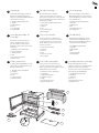
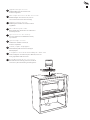
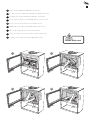
Montering
Om kaminen behöver läggas ned för att
förflyttas bör lösa delar demonteras.
Demontering av eldstadsbeklädnad beskrivs
i slutet av denna anvisning.
1 Eldstadsbeklädnad (Vermiculit)
2 Typskylt
3 Brasbegränsare
4 Roster
5 Inre bottenplåt
6 Varmluftsgaller
Vor der Montage
Wenn der Kaminofen in liegender
Position versetzt werden muss, sind lose
Komponenten zu demontieren. Demontage und
Brennraumauskleidung werden am Ende dieser
Anleitung beschrieben.
1 Feuerstättenauskleidung (Vermiculit)
2 Typenschild
3 Stehrost
4 Rost
5 Innere Bodenplatte
6 Warmluftgitter
Før montering
Hvis ovnen må legges ned for å flyttes,
bør løse deler demonteres. Demontering
av ildstedsbekledning er beskrevet til slutt
i denne veiledningen.
1 Brennplater og hvelv (Vermikulitt)
2 Typeskilt
3 Kubbestopper
4 Rist
5 Innvendig bunnplate
6 Varmluftsgitter
Avant de procéder au
montage
Les éléments non fixés devront être
retirés si le poêle doit être couché
pour être déplacé. Le démontage de
l’habillage est décrit à la fin des présentes
instructions.
1 Habillage du foyer (Vermiculite)
2 Plaque signalétique
3 Grille de retenue
4 Grille
5 Plaque de fond intérieure
6 Grille air chaud
Prior to installation
If the stove needs to be laid down for it
to be moved, loose components should be
removed. A description of how to remove
hearth cladding can be found at the end
of these instructions.
1 Fire bricks (Vermiculite)
2 Type plate
3 Fire bars
4 Grate
5 Inner bottom panel
6 Hot air grille
Før opstilling
Hvis brændeovnen skal lægges ned for
at blive flyttet, bør løsdele afmonteres.
Afmontering af ovnbeklædning beskrives
i slutningen af denne vejledning.
1 Ovnbeklædning (Vermiculite)
2 Typeskilt
3 Brændeholder
4 Rist
5 Indre bundplade
6 Varmluftsgitter
Ennen asennusta
Jos takka pitää siirtää kyljellään, irto-osat
pitää irrottaa. Palotilaverhouksen irrotus
kuvataan ohjeen lopussa.
1 Tulipesän verhous (vermikuliitti)
2 Tyyppikilpi
3 Suojareunus
4 Arina
5 Sisempi pohjapelti
6 Lämminilmaritilä
Prima del montaggio
Se è necessario smontare l’inserto per
spostarlo, rimuovere prima i componenti
liberi. L’operazione di smontaggio è descritta
alla fine delle presenti istruzioni.
1 Rivestimento interno del focolare
(vermiculite)
2 Targhetta identificativa
3 Griglia ferma-legna
4 Griglia
5 Piastra di fondo interna
6 Griglia di ventilazione
Voorafgaand aan montage
Als de kachel liggend moet worden
verplaatst, moeten losse onderdelen worden
gedemonteerd. Aan het eind van deze
instructies vindt u een beschrijving van de
demontage van de haardbekleding.
1 Haardbekleding (vermiculiet)
2 Typeplaatje
3 Houtvanger
4 Rooster
5 Bodemplaat binnenzijde
6 Heteluchtrooster

40
Ø ca 180 mm
Ø ca 180 mm
2
1
4
3
SE
DE
NO
FR
GB
DK
FI
IT
NL
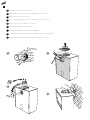
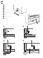
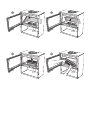
Bakåtanslutning till murad skorsten
Rückseitiger Anschluss an einen gemauerten Schornstein
Bakmontering til murt skorstein
Raccordement par l’arrière à une cheminée de maçonnerie
Rear connection to a masonry chimney
Tilslutning bagud til muret skorsten
Liitäntä taaksepäin muurattuun savupiippuun
Collegamento alla canna fumaria in muratura dal retro della stufa
Achterwaartse aansluiting op een gemetselde schoorsteen

41
SE
DE
NO
FR
GB
DK
FI
IT
NL
Toppanslutning till skorsten
Varmluftsgallret måste vara monterat innan
skorstenen toppansluts.
Oberseitiger Anschluss an den Schornstein
Das Warmluftgitter muss montiert sein, bevor ein
Schornsteinanschluss an der Oberseite erfolgt.
Toppmontering til skorstein
Varmluftsgitteret må være montert før skorsteinen
topptilkobles.
Raccordement par le haut
Monter la grille d’air chaud avant le raccordement à la
cheminée par le haut.
Top connection to the chimney
The hot air grille must be installed before chimney
top connection.
Toptilslutning til skorsten
Varmluftristen skal være monteret, før
skorstenen toptilsluttes.
Liitäntä ylöspäin savupiippuun
Lämminilmaritilä pitää asentaa ennen savupiipun
liitäntää ylöspäin.
Collegamento alla canna fumaria dal piano della stufa
Prima di collegare la canna fumaria al piano della stufa, assicurarsi
che la griglia dell'aria calda sia montata.
Bovenaansluiting op een schoorsteen
Het heteluchtrooster moet zijn gemonteerd, voordat de
schoorsteen op de bovenaansluiting wordt aangesloten.

42
HK HK
65 mm
1 2
HK
65 mm
HK
65 mm
3 4
SE
DE
NO
FR
GB
DK
FI
IT
NL
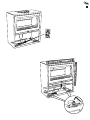
Tilluft
Zuluft
Tilluft
Arrivée d’air
Supply
Forbrændingsluft
Tuloilma
Alimentazione dell’aria
Toevoerlucht

43

44
1
3
2
2
1
SE
DE
NO
FR
GB
DK
FI
IT
NL
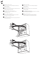
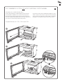
Luckan kan spärras i öppet läge, med hjälp av tryckknappen på
kaminens undersida.
Uppställning av luckan
Mithilfe der Taste an der Kaminofenunterseite kann die Tür in ihrer
geöffneten Stellung arretiert werden.
Låsing av døren i åpen posisjon
Døren kan låses i åpen posisjon ved hjelp av knappen
på undersiden av ovnen.
Mise en place de la porte
La porte peut être verrouillée en position ouverte, à l’aide du
bouton-poussoir sur le dessous du poêle.
The door can be held in the open position using the push button on
the underside of the stove.
Installation of the door
Spærring af lågen
Lågen kan spærres i åben position ved hjælp af trykknappen
under brændeovnen.
Luukun asennus
Luukku voidaan lukita avattuun asentoon takan alapuolella
olevalla painonapilla.
Lo sportello può essere bloccato in posizione aperta con un pulsante
posto sotto la camera di combustione.
Bloccaggio dello sportello
Het luik kan in geopende stand worden vergrendeld met
behulp van de drukknop aan de onderkant van de kachel.
Plaatsen van het luik
Aufstellung der Tür

45
43
1 2
SE
DE
NO
FR
GB
DK
FI
IT
NL
Demontera eldstadsbeklädnaden (Vermiculit)
So demontieren Sie die Brennraumauskleidung (Vermiculit)
Slik demonterer du ildstedsbekledningen (Vermikulitt)
Voici comment démonter l’habillage du foyer (Vermiculite)
How to remove the hearth surround (Vermiculite)
Sådan afmonterer du ovnbeklædningen (Vermiculite)
Näin irrotat tulipesän verhouksen (vermikuliitti)
Come smontare il rivestimento del focolare (vermiculite)
Zo demonteert u de kachelbekleding (vermiculiet)
Handle with care!
!

87
5 6

47
Damper Blocker for C310, C320 and C330
1
2
3
For installation in the UK and in smoke control areas
Contura 310, 320 and 330, 7 kW woodburning stoves has been
recommended as suitable for use in smoke control areas. This
when burning wood logs and operated in accordance with these
instructions and when fitted with a permanent stop to prevent clo-
sure of the air control unit beyond 31% open position.
Mandatory for smoke control areas
The permanent stop must be installed if the appliance is to be
used in a smoke control area, this stop must not be removed in
smoke control areas, otherwise an offence will be committed if
the appliance is used without the permanent stop in place.
GB

811303 IAV SE-EX C310-4
2023-10-18 NIBE AB · Box 134 · 285 23 Markaryd · Sweden
contura.eu
-
 1
1
-
 2
2
-
 3
3
-
 4
4
-
 5
5
-
 6
6
-
 7
7
-
 8
8
-
 9
9
-
 10
10
-
 11
11
-
 12
12
-
 13
13
-
 14
14
-
 15
15
-
 16
16


Contura 310 & 310G Istruzioni per l'uso
- Categoria
- Stufa a legna
- Tipo
- Istruzioni per l'uso
in altre lingue
Documenti correlati
-
Contura 620T Style Istruzioni per l'uso
-
-
-
-
-
-
-
-
-