ISCOM072-1809
Mod. VE 602E
Descrizione
NCV
NCV
OFF
400/600A
2/20A
MAX
FUNC HOLD
VE 601E
NCV
NCV
OFF
60A
600A
Hz
Hz%
FUNC
ZERO+Hz
HOLD
VE 602E
AC/DC CLAMPMETER
/
/
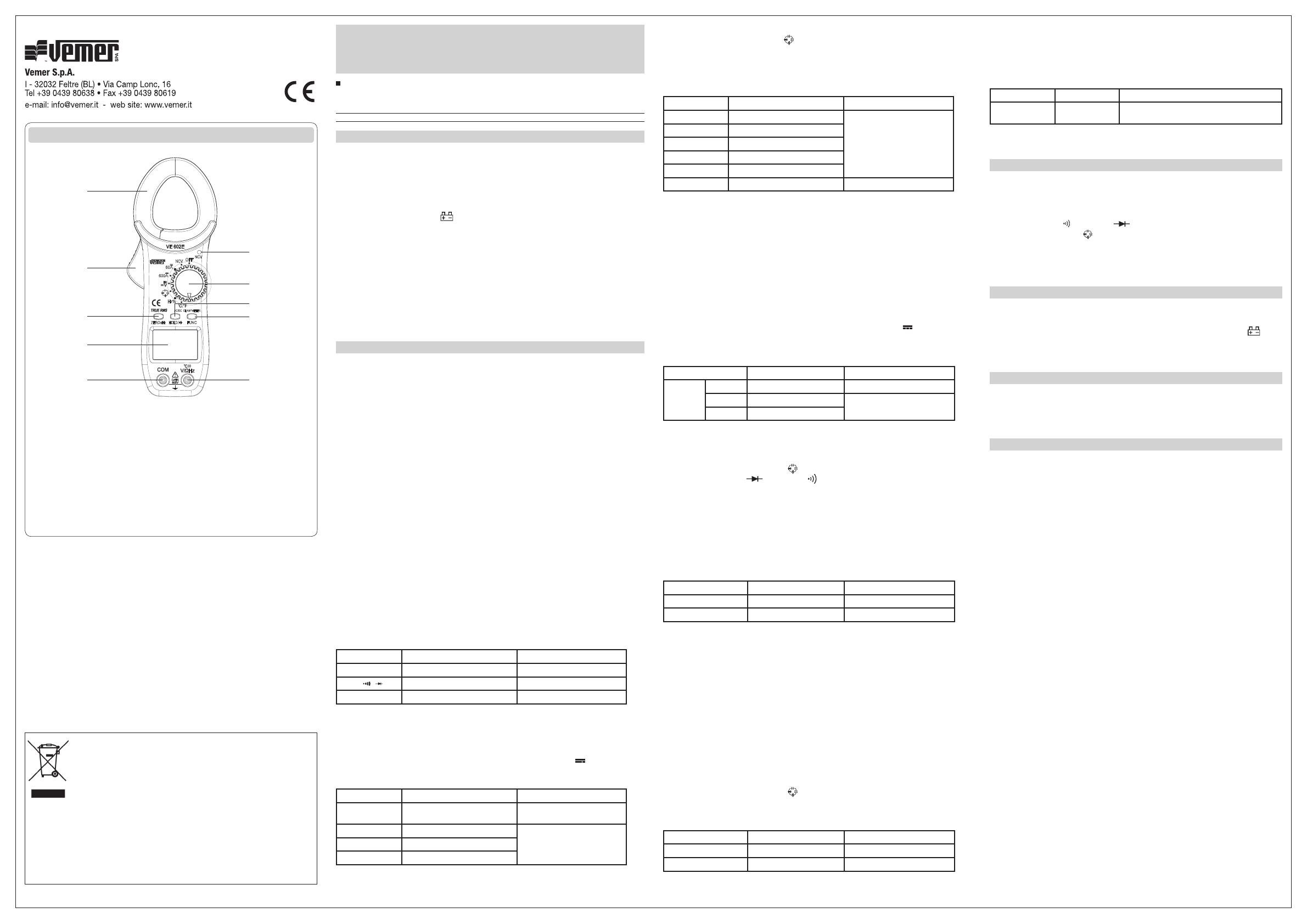
1. Ganasce
2. Pulsante apertura ganasce
3. Display LCD
4. LED indicazione NCV
5. Selettore di funzione
6. Tasto Zero/Hz
7. Tasto Hold
8. Tasto FUNC
9. Jack COM
10. Jack V/Ω/Hz
Manuale d'uso
PINZA DIGITALE AC/DC TRMS
Leggere attentamente tutte le istruzioni
Pinza digitale per la misura di correnti AC/DC, tensioni AC/DC, continuità, test del diodo, frequenza, capacità,
temperatura. Categoria di sovratensione CAT II 600V e grado d'inquinamento 2.
Codice Modello Descrizione
VE772500 VE 602E Pinza digitale AC/DC TRMS
CARATTERISTICHE GENERALI
• Indicazione massima: 6000 punti
• Lettura della misura: 2 volte ogni secondo
• Display retroilluminato
• Pulsante per attivazione funzione data hold
• Visualizzazione automatica fuori scala (visualizzazione “OL”)
• Alimentazione: 2x1,5V tipo AAA
• Segnalazione batteria scarica “ ”sul display
• Indicazione automatica della polarità per misure DC
• Indicazione sonora nel caso di misure fuori scala di tensioni, correnti, resistenze
• Prova diodo con corrente costante 1mA
• Test di continuità con indicazione sonora sotto i 50 ohm
• Condizioni ottimali di funzionamento: 23°C ± 5°C. <75% RH
• Temperatura di funzionamento: 0 ÷ 40 °C, <75% RH
• Condizioni di immagazzinamento: -10°C ÷ +50°C, <80% RH
• Peso e dimensioni: 180g circa, 186x75x28 mm
• Accessori in dotazione: manuale d’uso, puntali per test, batterie, sonda di temperatura
termocoppia K
FUNZIONAMENTO
Precauzioni
1. Non utilizzare il dispositivo se qualche parte di esso è danneggiata.
2. Controllare la carica della batteria spostando il selettore di funzione dalla posizione OFF
in qualsiasi altra posizione. Se la batteria è scarica, compare l’indicazione sul display: far
riferimento alla sezione MANUTENZIONE in questo manuale per la sostituzione della batteria
3. Il simbolo vicino le boccole indica di far attenzione a non superare i valori di tensione o
corrente stabiliti al fine di prevenire danneggiamenti al circuito interno
4. Posizionare il selettore nella posizione relativa che si vuole misurare prima di effettuare
l’operazione
5. Se l’ordine di grandezza della tensione o della corrente che si deve misurare non è noto a
priori, posizionare il selettore nella scala più elevata ed eventualmente posizionare il selettore
su una scala inferiore successivamente
6. Se il display visualizza il simbolo “OL” (over-range) posizionare il selettore su una scala più
alta
7. Non utilizzare il dispositivo in ambienti esplosivi o polverosi
8. Non misurare correnti superiori a 10A per più di 15 secondi per prevenire rotture dello
strumento o pericoli per l’utente
9. Per evitare scosse elettriche, disconnettere i puntali prima di rimuovere la cover posteriore
10. Per una protezione continua contro gli incendi, sostituire i fusibili solo con altri aventi le
stesse caratteristiche
11. CAT II - Categoria di misura II. Il dispositivo è progettato per l’utilizzo in circuiti direttamente
connessi alla bassa tensione (utilizzabile ad esempio per applicazioni domestiche, strumenti
portatili e similari). Non utilizzare per misure con categoria di misura III e IV.
ATTENZIONE
Per evitare di danneggiare il dispositivo, non superare i limiti di misura riportati nella seguente
tabella:
Funzione Terminali Limiti di ingresso
DCV/ACV V/Ω + COM 600V DC or 600V rms AC
Ω/ / V/Ω + COM 250V DC o rms AC
Hz V/Ω + COM 250V DC o rms AC
Misure di tensioni AC/DC
1. Posizionare il selettore nella scala V
2. Collegare il puntale nero al jack “COM” e il puntale rosso al jack V/Ω/Hz e successivamente
posizionare i puntali sull’elemento da testare
3. Premere il tasto FUNC per selezionare la misura AC o DC. Il simbolo ~ o è visualizzato
sul display, assieme al valore della tensione.
Range Risoluzione Precisione
600mV 0,1mV
±(1,2% of rdg + 5dgts) DC V
±(1,5% of rdg + 5dgts) AC V
6V 1mV
±(1,0% of rdg + 2dgts) DC V
±(1,2% of rdg + 3dgts) AC V
60V 10mV
600V 100mV
Range di frequenza: da 40 a 400Hz
Misura delle resistenze
1. Posizionare il selettore nella scala e successivamente premere il tasto FUNC finchè il
display visualizza la scritta AUTO e sulla destra l’unità di misura della resistenza Ω
2. Collegare il puntale nero al jack “COM” e il puntale rosso al jack V/Ω/Hz e successivamente
posizionare i puntali sull’elemento da testare.
3. Il valore della resistenza è visualizzato sul display
Range Risoluzione Precisione
600Ω 0,1Ω
±(1,5% of rdg + 3dgts)
6KΩ 1Ω
60KΩ 10Ω
600KΩ 100Ω
6MΩ 1KΩ
60MΩ 10KΩ ±(2,5% of rdg + 3dgts)
Nota 1: se il valore della resistenza da misurare è superiore alla scala impostata, sul display compare
l'indicazione “OL” (over-range): selezionare una scala più alta. L’indicazione di over-range viene
visualizzata anche quando i puntali non sono connessi ad alcun elemento da testare
Nota2: Se la resistenza da misurare è superiore a 2 MOhm, potrebbero essere necessari alcuni secondi
affinchè il valore visualizzato sul display divenga stabile. Questo comportamento è normale
per valori di resistenza elevati
Nota 3: quando si effettuano misure di resistenza, assicurarsi che il circuito in esame non sia in tensione
e che i componenti capacitivi siano completamente scarichi
Misure di corrente AC/DC
1. Posizionare il selettore nella scala 60A oppure 600A. Se l’ordine di grandezza della corrente
non è noto a priori, posizionare il selettore nella scala più alta; eventualmente se la misura
dovesse indicare un valore basso, posizionare il selettore nella scala 60A.
2. Premere il tasto FUNC per selezionare la misura AC o DC. Il simbolo ~ o è visualizzato
sul display.
3. Abbracciare con la ganascia il cavo interessato alla misura. Il valore della corrente è
visualizzato sul display.
Range Risoluzione Precisione
AUTO
RANGE
6A 1mA ±(3% of rdg + 10dgts)
60A 10mA ±(2,5% of rdg + 10dgts) AC A
±(3% of rdg + 5dgts) DC A
600A 100mA
Range di frequenza: da 40 a 400Hz.
Test del diodo/continuità
1. Collegare il puntale nero al jack “COM” e il puntale rosso al jack V/Ω/Hz
2. Posizionare il selettore in posizione e premere il tasto FUNC finche sul display viene
visualizzato il simbolo (test diodo) o (test continuità).
3. Posizionare i puntali sull’elemento da testare.
4. Nel caso del test del diodo, collegare il puntale rosso all'anodo e il puntale nero al catodo.
Il valore della tensione di lavoro del diodo è visualizzato sul display
5. Nel caso del test di continuità il buzzer suona per valori di resistenza inferiori a 50Ω.
Test di frequenza
1. Collegare il puntale nero al jack “COM” e il puntale rosso al jack V/Ω/Hz
2. Posizionare il selettore in posizione Hz e posizionare i puntali sull’elemento da testare.
3. Il valore della frequenza è visualizzato sul display
Range Risoluzione Precisione
10 ~ 1M Hz 1Hz ±(1,0% of rdg + 2dgts)
10~50K Hz at V range 1Hz ±(1,5% of rdg + 4dgts)
Limiti tensione di ingresso: 30V~600V (<50K Hz); Massimo 10V(>50K Hz).
É possibile misurare frequenze da 10 Hz a 50K Hz. Premere il tasto ZERO/Hz e leggere il valore di
frequenza direttamente sul display se il valore di tensione è compreso tra 30 e 600V.
Se la frequenza è superiore a 50K Hz la tensione di ingresso deve essere minore di 10V al fine di
garantire la precisione di misura.
NCV test – Non-Contact-Voltage AC
1. Posizionare il selettore in posizione NCV: il led relativo lampeggia
2. Avvicinare la ganascia al segnale AC
3. Se il valore è superiore a 100V AC il led NCV lampeggia velocemente
Nota: non è necessario alcun contatto tra dispositivo e elemento da testare. Durante il test il
display non visualizza alcun valore.
Misure di capacità
1. Collegare il puntale nero al jack “COM” e il puntale rosso al jack V/Ω/Hz
2. Posizionare il selettore in posizione e premere il tasto FUNC finche sul display viene
visualizzata la scritta AUTO e l'unità di misura F.
3. Posizionare i puntali sull’elemento da testare. Assicurarsi che il condensatore non sia in
tensione. Il valore della capacità è visualizzato sul display.
Range Risoluzione Precisione
5nF ~ 5µF 0,01n~0,01uF ±(2,5% of rdg + 10dgts)
5µF ~ 200µF 0,1uF ±(4,0% of rdg + 20dgts)
Limiti tensione di ingresso: 30V~600V (<50K Hz); Max. 10V(>50K Hz).
Misura della temperatura
1. Collegare il pin nero della sonda in dotazione al jack “COM” e il pin rosso
al jack V/Ω/Hz
2. Posizionare il selettore in posizione °C/°F e premere FUNC per selezionare °C oppure °F.
3. Posizionare la sonda in dotazione sull’elemento da testare (o al suo interno)
4. Il valore della temperatura è visualizzato sul display in gradi centigradi
Range Risoluzione Precisione
0°C ÷ 750°C
(32°F ÷ 1382°F)
1°C
(1°F)
±(2,0%+1) per temperature 0 ÷ 400°C (32 ÷ 752°F)
±(2,5%+1) per temperature 400 ÷ 750°C (752 ÷ 1382°F)
Nota: la temperatura massima misurabile con la termocoppia in dotazione è 250°C/482°F;
valori fino a 300°C/572°F sono accettati per brevi periodi.
DESCRIZIONE TASTI
• Tasto Hold: quando premuto il display visualizza l’ultima misura effettuata e viene
visualizzato il simbolo “H”. La funzione di data hold viene disattivata automaticamente se il
selettore di funzione viene ruotato in un’altra posizione.
• Tasto FUNC: premere questo tasto per selezionare tra tensioni AC/DC, correnti AC/DC,
misura della continuità , prova diodo , o temperatura °C/°F quando il selettore di
funzione è in posizione A, V o .
• Tasto Zero/Hz: premere questo tasto per visualizzare alternativamente il valore di
tensione o frequenza quando il selettore di funzione è in posizione V~. Premere questo tasto
per azzerare il valore visualizzato sul display.
MANUTENZIONE
Attenzione : prima di procedere con la sostituzione della batteria rimuovere i puntali e
posizionare il selettore in posizione OFF
Quando le batterie sono prossime alla scarica, sul display compare l’indicazione “ "
Svitare le viti poste sul retro del dispositivo e rimuovere la cover.
Sostituire quindi le batterie. Utilizzare batterie tipo AAA da 1,5V (2 pezzi).
PULIZIA
Per pulire il dispositivo usare un panno umido dopo averlo spento ed aver tolto i puntali.
Non usare liquidi, solventi o altri prodotti che possano ridurre il livello di sicurezza del
dispositivo.
NORME DI RIFERIMENTO
La conformità alle Direttive Comunitarie:
2014/35/UE (LVD), 2014/30/UE (E.M.C.D.)
è dichiarata con riferimento alle seguenti Norme armonizzate:
• CEI EN 61010-1
• CEI EN 61010-031
• CEI EN 61326-1, EN 61326-2-2
1.
2.
6.
3.
9.
4.
5.
8.
7.
10.
ai sensi dell’art. 26 del Decreto Legislativo 14 marzo 2014, n. 49
“Attuazione della direttiva 2012/19/UE
sui rifiuti di apparecchiature elettriche ed elettroniche (RAEE)”
Il simbolo del cassonetto barrato riportato sull’apparecchiatura o sulla sua
confezione indica che il prodotto alla fine della propria vita utile deve essere raccolto
separatamente dagli altri rifiuti. L’utente dovrà, pertanto, conferire l’apparecchiatura
giunta a fine vita agli idonei centri comunali di raccolta differenziata dei rifiuti
elettrotecnici ed elettronici.
In alternativa alla gestione autonoma è possibile consegnare l’apparecchiatura che si desidera
smaltire al rivenditore, al momento dell’acquisto di una nuova apparecchiatura di tipo equivalente.
Presso i rivenditori di prodotti elettronici con superficie di vendita di almeno 400 m2 è inoltre possibile
consegnare gratuitamente, senza obbligo di acquisto, i prodotti elettronici da smaltire con dimensioni
inferiori a 25 cm.
L’adeguata raccolta differenziata per l’avvio successivo dell’apparecchiatura dismessa al riciclaggio,
al trattamento e allo smaltimento ambientalmente compatibile contribuisce ad evitare possibili effetti
negativi sull’ambiente e sulla salute e favorisce il reimpiego e/o riciclo dei materiali di cui è composta
l’apparecchiatura.


