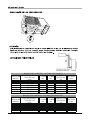
Airwell Aqu@Scop Advance R410A Guida d'installazione
- Categoria
- Condizionatori d'aria a sistema split
- Tipo
- Guida d'installazione

English
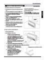
Installation manual
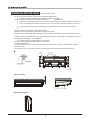
Indoor unit floor ceiling type
AIR CONDITIONER
FLOOR CEILING
ENGLISH

GENERAL RECOMMENDATIONS
- Congratulations for having selected an our air conditioner.
SAFETY DIRECTIONS
- Follow the safety rules in force when you are working on your appliance.
- Installation and maintenance of the equipment must only be performed by qualified specialists in
accordance with the rules of good workmanship and prevailing standards and instructions.
- Make sure that the power supply and its frequency are adapted to the required electric current of
operation, taking into account specific conditions of the location and the current required for any
other appliance connected with the same circuit.
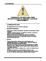
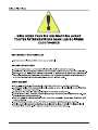
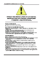
WARNING
- Cutoff power supply before starting to work on the appliance. The manufacturer declines any
responsibility and the warranty becomes void if these instructions are not respected.
- If you meet a problem, please call the Technical Department of your area.
- If possible, assemble the mandatory or optional accessories before placing the appliance on its
final Iocation.(see instruc- tions provided with each accessory)
- In order to become fully familiar with the appliance, we suggest to read also our Technical
Instructions.
- The information contained in these Instructions are subject to modification without advance notice.
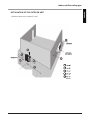
IT IS MANDATORY TO CUT OFF POWER SUPPLY
BEFORE STARTING TO WORK IN THE ELECTRIC
CASING BOXES.
2
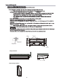
- For appliances with supplementary heaters, the minimum clearance from the appliance to
combustible is 50cm other wise, it will cause fire.
Indoor unit floor ceiling type

Indoor unit floor ceiling type
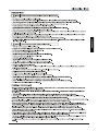
Do not attempt to install this air conditioner by yourself.
This unit contains no user-serviceable parts. Always consult authorized service personnel for repairs.
When moving, consult authorized service personnel for disconnection and installation of the unit.
Do not become excessively chilled by staying for lengthy periods in the direct cooling airflow.
Do not insert fingers or objects into the outlet port or intake grilles.
Do not start and stop air conditioner operation by disconnecting the power supply cord and so on.
Take care not to damage the power supply cord.
In the event of a malfunction (burning smell, etc.),immediately stop operation, disconnect the power supply plug, and consult authorized
service personnel.
If the power supply cord of this appliance is damaged, it should only be replaced by the authorized service personal, since special purpose
tools and specified cord are required.
Provide occasional ventilation during use.
Do not direct air flow at fireplaces or heating apparatus.
Do not climb on, or place objects on, the air conditioner.
Do not hang objects form the indoor unit.
Do not set flower vases or water containers on top of air conditioners.
Do not expose the air conditioner directly to water.
Do not pull power supply cord.
Turn off power source when not using the unit for extended periods.
Check the condition of the installation stand for damage.
Do not place animals or plants in the direct path of the air flow.
Do not drink the water drained from the air conditioner.
Do not use in applications involving the storage of foods, plants or animals, precision equipment,or art works.
Connection valves become hot during Heating; handle with care.
Do not apply any heavy pressure to radiator fins.
Operate only with air filters installed.
Do not block or cover the intake grille and outlet port.
Ensure that any electronic equipment is at least one metre away from either the indoor or outdoor units.
Avoid installing the air conditioner near a fireplace or other heating apparatus.
When installing the indoor and outdoor unit, take precautions to prevent access to infants.
Do not use inflammable gases near the air conditioner.
Danger This sign warns of death or serious injury.
Caution This sign warns of damage to property.
PRECAUTIONS
Set a suitable room temperature; excessively low room temperature is not good for your health and wastes electricity. Avoid frequent
setting of the temperature.
During cooling, avoid direct sun. Keep curtains and blinds closed. Close doors and windows to keep the cool air in the room.
Avoid generating heat or using of heating appliances while the air conditioner in cooling mode.
Make sure that the air flap is positioned properly: horizontal flow in cooling and downward vertical flow for heating.
Keep the room temperature uniform by adjusting the left/right vertical air blades.
Position the air flap and the left/right air blades in such a manner as to prevent your body from being exposed directly to air drafts.
During prolonged operation, ventilate the room occasionally by opening a window from time to time.
In a power failure, the microprocessor memory is retained. When restarted,operation will be resumed in the last mode of
operation. However, if the timer was used, the unit will be turned off by the timer only if the remote control is aimed at the
unit. Otherwise the power failure will cause the timer data to be erased from the microprocessor memory.
After turning on, allow more than 3 minutes for cooling, heating or dry operation to start.
When DRY mode is used, make sure that the room temperature is between 20 and 27 . When used out of this range,
the unit may protect itself and become inoperative.
When COOL or DRY modes are used, make sure that the room's relative humidity is below 78% lf the unit is used for a
prolonged periods of time in high humidity, moisture may form on the air outlet and drip down.
Remote control signals may not be received if the indoor unit controls cover is exposed to direct sunlight or strong light. ln
such a case, block the sunlight or dim the lighting.
The remote control is operative in a range of 8 meters. lf you are out of range, the remote control may have difficulties in
transmitting signals.
OPERATION TIPS
3
The appliance is not intended for use by young children of infirm persons without supervision.
Please pre-heat the air conditioner for at least 12 hours before operation. lf use it for a long time, please keep the power on.
ENGLISH

Indoor unit floor ceiling type
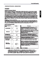
SUMMARY
DESCRIPTION
Installation/service tools.........................................................................................................................5
Operating temperature range................................................................................................................6
Dimensions of Indoor Unit .....................................................................................................................6
Dimensions of Outdoor Units.................................................................................................................6
INSTALLATION
Location of the Indoor Unit .................................................................................................................7-8
Location of the Outdoor Unit..................................................................................................................9
Refrigerant Line...................................................................................................................................10
Installation.......................................................................................................................................
1
Electrical Connections....................................................................................................................
Final Tasks.................................................................................................................
4

Indoor unit floor ceiling type
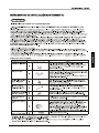
CAUTION
Incidentally, the "refrigerant cylinder" comes with the refrigerant designation (R410A) and protector coating in the
U.S's ARI specified rose color (ARI color code: PMS 507).
Also, the "charge port and packing for refrigerant cylinder" requires 1/2 UNF 20 threads per inch corresponding
to the charge hose's port size.
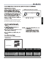
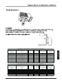
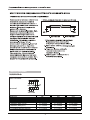
New Refrigerant Air Conditioner Installation
THIS AIR CONDTIONER ADOPTS THE NEW HFC REFRIGERANT (R410A) WHICH DOES NOT DESTROY OZONE
LAYER. R410A refrigerant is apt to be affected by impurities such as water, oxidizing membrane, and oils because the working
pressure of R410A refrigerant is approx. 1.6 times of refrigerant R22. Accompanied with the adoption of the new refrigerant, the
refrigeration machine oil has also been changed. Therefore, during installation work, be sure that water, dust, former refrigerant,
or refrigeration machine oil does not enter into the new type refrigerant R410A air conditioner circuit.
To prevent mixing of refrigerant or refrigerating machine oil, the sizes of connecting sections of charging port on main unit and
installation tools are different from those used for the conventional refrigerant units. Accordingly, special tools are required for
the new refrigerant (R410A) units. For connecting pipes, use new and clean piping materials with high pressure fittings made for
R410A only, so that water and/or dust does not enter. Moreover, do not use the existing piping because there are some
problems with pressure fittings and possible impurities in existing piping.
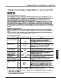
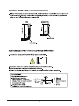
Changes in the product and components
In air conditioners using R410A, in order to prevent any other refrigerant from being accidentally charged, the service port
diameter size of the outdoor unit control valve (3 way valve) has been changed. (1/2 UNF 20 threads per inch)
In order to increase the pressure resisting strength of the refrigerant piping, flare processing diameter and
opposing flare nuts sizes have been changed. (for copper pipes with nominal dimensions 1/2 and 5/8)
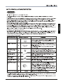
As the working pressure is high, it is impossible to measure the
working pressure using conventional gauges. In order to prevent
any other refrigerant from being charged, the port diameters have
been changed.
In order to increase pressure resisting
strength, hose materials
and port
sizes have been changed (to 1/2 UNF 20 threads per
inch).
When purchasing a charge hose, be sure to confirm the port size.
As working pressure is high and gasification speed is fast, it is
difficult to read the indicated value by means of charging cylinder,
as air bubbles occur.
The size of opposing flare nuts have been increased. Incidentally,
a common wrench is used for nominal diameters 1/4 and 3/8.
By increasing the clamp bar's receiving hole size, strength of
spring in the tool has been improved.
Used when flare is made by using conventional flare tool.
Connected to conventional vacuum pump. It is necessary to use
an adapter to prevent vacuum pump oil from flowing back into
the charge hose. The charge hose connecting part has two ports
-- one for conventional refrigerant (7/16 UNF 20 threads per inch)
and one for R410A. If the vacuum pump oil (mineral) mixes with
R410A a sludge may occur and damage the equipment.
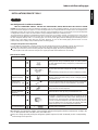
Exclusive for HFC refrigerant.
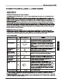
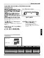
New tools for R410A Applicable to R22 model Changes
Gauge manifold
Charge hose
Electronic balance for
refrigerant charging
Torque wrench
(nominal dia. 1/2, 5/8)
Flare tool (clutch type)
Gauge for projection
adjustment
Vacuum pump adapter
Gas leakage detector
New tools for R410A
INSTALLATION/SERVICE TOOLS
5
ENGLISH

Indoor unit floor ceiling type
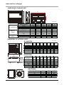
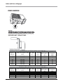
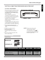
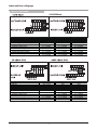
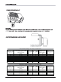
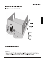
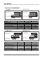
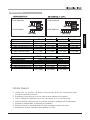
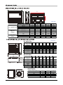
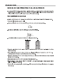
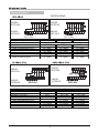
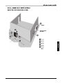
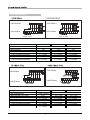
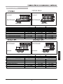
DIMENSIONS OF OUTDOOR UNITS
DIMENSIONS OF INDOOR UNIT
6
Unit: mm
Unit: mm
B
E
C
D
A
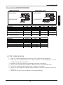
Model (KBtu/h) A B C D E
18/24 1068 675 235 983 220
30 1285 675 235 1200 220
36/48/60 1650 675 235 1565 220
12/18/24 1068 675 235 983 220
30/36/48 1285 675 235 1200 220
60 1650 675 235 1565 220
36 1285 675 235 1200 220
48/60 1650 675 235 1565 220
DC INVERTER
ON-OFF
(50Hz)
ON-OFF
(60Hz)
A
H
B
C
D
E
F
CAPACITY
(KBtu/h)
A B C D E F H
12 780 548 266 300 241 250 540
18 760 530 290 315 270 285 590
24 845 560 335 360 312 320 700
30/36 990 624 366 396 340 345 965
48/60 938 634 404 448 368 392 1369
CAPACITY
(KBtu/h)
A B C D E F H
12 760 530 290 315 270 285 590
18 845 560 335 360 312 320 700
24/30 900 590 333 355 302 315 860
36 990 624 366 396 340 345 965
48/60 938 634 404 448 368 392 1369
A
B
C
Capacity (KBtu/h) A B C
36 759 600 600
48 759 710 710
60 843 710 710
DC INVERTER
ON-OFF(50Hz
ON-OFF(60Hz

Indoor unit floor ceiling type
7
it
condersation water is easily drained
out.
Such a place that can handle the weight of indoor unit.
Such a place which has easy access for maintenance.
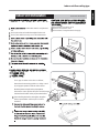
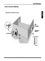
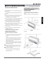
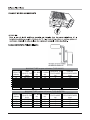
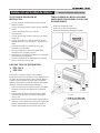
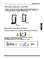
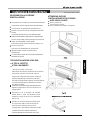
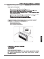
SELECTION OF INSTALLATION LOCATION.
THERE ARE 2 STYLES OF INSTALLATION.
CEILING TYPE
FLOOR TYPE
Each type is similar to the other as follows;
Determine the mounting position on ceiling or wall
by using paper pattern to indicate indoor frarne.
Mark the pattern and pull out the paper pattern.
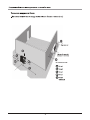
Remove the return grill,the side panel and the hanger
bracket from the indoor unit as per procedure bellow.
Press the fixing knob of the relurn grilles, the grilles
will be opened wider and then pull it out from
the indoor.
CAUTION FOR INSTALLATION WHERE
AIR CONDITIONER TROUBLE IS LIKELY
TO OCCUR.
Where there is too much of oil.
Where it is acid base area.
Where there is irregular electrical supply.
Indoor Unit Instrallation
INSTALLATION INSTRUCTIONS
INSTALLATION
PAPER PLANK
100cm
or more
30cm
or more
60cm
or more
60cm
or more
150cm
or more
ENGLISH

Indoor unit floor ceiling type
8
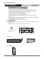
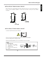
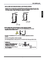
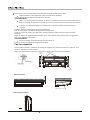
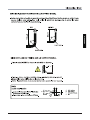
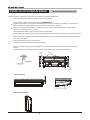
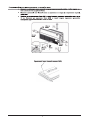
Indoor Unit Installation
a
Side board
Hanging arm
Hanging
screw bolt
Ceiling Installation
20mm
Downward slope : (1-2)/100
Wall Mounting Installtion

Indoor unit floor ceiling type
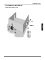
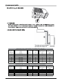
INSTALLATION OF THE OUTDOOR UNIT
- Minimum clearance to respect (in mm).
minimum
9
ENGLISH

Indoor unit floor ceiling type
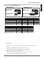
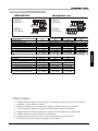
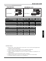
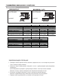
REFRIGERANT CONNECTIONS
10
CAPACITY
(KBtu/h)
TUBE OD: LIQUID - GAS
(Inch)
A- L.MAX
(m)
B - H.MAX
(m)
LENGTH OF
PRECHARGE
(m)
ADDITIONAL
CHARGE
(g/m)
12 1/4"-1/2" 20 10 5 15
18 1/4"-1/2" 25 15 5 15
24 3/8"-5/8" 25 15 5 30
30 3/8"-3/4" 25 15 5 30
36 3/8"-3/4" 30 20 5 30
48/60 3/8"-3/4" 50 25 5 30
CAPACITY
(KBtu/h)
TUBE OD: LIQUID - GAS
(Inch)
A- L.MAX
(m)
B - H.MAX
(m)
LENGTH OF
PRECHARGE
(m)
ADDITIONAL
CHARGE
(g/m)
12 1/4"-3/8" 20 10 5 15
18 1/4"-1/2" 30 20 5 15
24/30 3/8"-5/8" 50 25 5 30
36/48/60 3/8"
-5/8" 65 25 5 30
MAXIMUM PIPE LENGTH & HEIGHT (TYPE ON-OFF)
MAXIMUM PIPE LENGTH & HEIGHT (TYPE INVERTER)

Indoor unit floor ceiling type
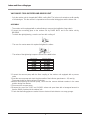
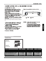
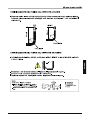
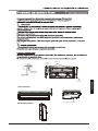
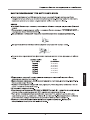
INSTALLATION OF TUBING ON WALL SUPPORT
- After choosing your coolant tubing input location (right, left or rear), you can set up your tubing. To
do this, use the installation template in order to form the tubes correctly and thus facilitate
connection.
11
- Fit the nuts of the (for med) tubing into the recess provided on the template.
- Secure the tubing with the clamps provided.
- Remove the tubing template; you can now install your unit on its support.
INSTALLATION OF TUBING ON WALL SUPPORT
- Locate the LIQUID tube above the GAS tube.
NOTE
output to the rear
- The slanted hole prevents
condensates or rain from
entering the unit.
- Fit a Dia. 70 mm sleeve into
the hole.
ENGLISH

Indoor unit floor ceiling type
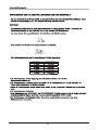
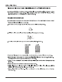
2 Connect the vacuum pump with the flare coupling of the outdoor unit equipped with a process
valve.
3 Start the vacuum pump and check that the needle of the indicator goes down to - 0,2 mm Hg.
The pump should run during at least 15 minutes.
4 Before disconnecting the vacuum pump, check that the vacuum indicator remains in the same
position during five minutes.
5 Disconnect the vacuum pump.
6 Remove the cap of the "GAS" and "LIQUID" valves and open them with a hexagonal wrench to
free the R410A contained in the outdoor unit.
7 Check that the linking pipes are sealed. Use an electronic leak detector or a soapy sponge.
VACUUM OF COOLING PIPES AND INDOOR UNIT
- Only the outdoor unit is charged with R410A cooling fluid. The indoor unit contains a small quantity
of a neutral gas. This the reason it is imperative to vacuum the linking pipes and the indoor unit.
ASSEMBLY
- The outdoor unit is equipped with a valve allowing to vacuum the installation (large valve)
1 Connect the connecting pipes to the outdoor unit by FLARE NUTS and to the indoor unit by
BRAZING
- To obtain the right tightening, cover the sur face with cooling oil.
- The use of a counter wrench is required to tighten the valves.
- The values of the tightening torque are shown in the table below.
1
Pipe Diameter Tightening Torque

Capacity 36K 48K
60K
Power supply
Fuse Rating(ODU/IDU) 30A / 16A 45A/16A 50A/16A
1- Power Cable (ODU)
3 x 4.0mm
2
3 x 6.0mm
2
3 x10.0mm
2
2- Power Cable (IDU)
3 x 1.0mm
2
3 x 1.0mm
2
3 x 1.0mm
2
3- Interconnecting Cable
Indoor & Outdoor
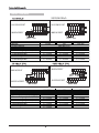
ON-OFF TYPE(60Hz)
36/48/60 KBtu/h
220V 1~ 60Hz
220V 1~ 60Hz
Indoor unit floor ceiling type
100
40
8
8
BA
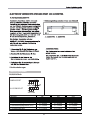
ELECTRICAL CONNECTION BETWEEN INDOOR AND OUTDOOR UNIT
ELECTRICAL REQUIREMENTS
Electrical wiring and connections should
be made by qualified electricians and in
accordance with local electrical codes
and regulation. The air conditioner units
must be grounded.
The air conditioner unit must be
connected to an adequate power outlet
from a separate branch circuit protected
by a time delay circuit breaker, as
specified on unit's nameplate.
Voltage should not vary beyond 10% of
the rated voltage.
An all-pole disconnection switch having a
contact separation of at least 3mm in all
poles should be connected in fixed wiring.
1. To connect the indoor unit to the
outdoor unit use the following electrical
cables.
NOTES: The wire color code can be
selected by the installer.
2. Prepare the needed cables for
electrical connection.
3. Connect the cable ends to the
terminals of the indoor and outdoor
units.
4. Secure the multiple wire power cable
with the cable clamps.
The temperature of refrigerant
circuit will be high, please keep
the interconnection cable away
from the copper tube.
1
ENGLISH
2 x 0.5mm
2
2 x 0.5mm
2
2 x 0.5mm
2
C1 N1
C1 N1

ON-OFF TYPE(50Hz)
Capacity 12/18K 24K 30K/36K
Power supply
Fuse Rating 16A 25A 30A
1- Power Cable (IDU)
3 x 1.5mm
2
3 x 2.5mm
2
3 x 4.0mm
2
2- Interconnecting Cable
3 x 1.5mm
2
3 x 2.5mm
2
3 x 4.0mm
2
3- Interconnecting Cable
2 x 1.0mm
2
3 x 1.0mm
2
3 x 1.0mm
2
4- Interconnecting Cable
2 x 0.5mm
2
2 x 0.5mm
2
2 x 0.5mm
2
From Indoor
Capacity 36K (3Ph) 48K 60K
Power supply From Outdoor
Fuse Rating (ODU/IDU) 20A /- 25A / 16A 25A / 16A
1- Power Cable (ODU)
5 x 2.5mm
2
5 x 2.5mm
2
5 x 2.5mm
2
2- Power Cable (IDU) -
3 x 1.0mm
2
3 x 1.0mm
2
3- Interconnecting Cable
3 x 1.0mm
2
3 x 0.5mm
2
3 x 0.5mm
2
4- Interconnecting Cable
3 x 1.0mm
2
- -
Indoor & Outdoor
Indoor unit floor ceiling type
1
24/30/36KBtu/h
230V 1~ 50Hz 230V 1~ 50Hz

INVERTER TYPE
Capacity 18k 24k 30k 36k
Power supply
Fuse Rating (ODU/IDU) 16A / 10A 20A / 10A 30A / 10A 30A / 10A
1- Power Cable (ODU)
3 x 2.5mm
2
3 x 2.5mm
2
5 x 2.5mm
2
5 x 4.0mm
2
2- Power Cable (IDU)
3 x 1.0mm
2
3 x 1.0mm
2
3 x 1.0mm
2
3 x 1.0mm
2
3- Interconnecting Cable
3 x 0.5mm
2
3 x 0.5mm
2
3 x 0.5mm
2
3 x 0.5mm
2
Indoor & Outdoor
Capacity 36k(3Ph) 48K 60K
Power supply
Fuse Rating (ODU/IDU) 20A / 10A 25A / 10A 25A / 10A
1- Power Cable (ODU)
5 x 2.5mm
2
5 x 2.5mm
2
5 x 2.5mm
2
2- Power Cable (IDU)
3 x 1.0mm
2
3 x 1.0mm
2
3 x 1.0mm
2
3- Interconnecting Cable
3 x 0.5mm
2
2 x 0.5mm
2
2 x 0.5mm
2
Indoor & Outdoor
Indoor unit floor ceiling type
ENGLISH
1. Check all valve caps and ensure that they had been tightened properly. Close the valve
cover.
2. Fill gaps on the wall between hole sides and tubing with sealer.
3. Attach wiring and tubing to the wall with clamps where necessary.
4. Operate the unit for no less than 5 minutes at heating or cooling mode.
5. Explain filter removal, cleaning and installation.
6. Operate the air conditioner together with the customer and explain all functions.
7. Give the operating and installation manuals to the customer.
FINAL TASKS


DEUTSCH
Deutsch
Montageanleitung
TRUHEN-SPLITKLIMAGERÄTE
Truhen-splitklimageräte


DEUTSCH

11
13
15
Letzte vorkehrungen
La pagina sta caricando ...
La pagina sta caricando ...
La pagina sta caricando ...
La pagina sta caricando ...
La pagina sta caricando ...
La pagina sta caricando ...
La pagina sta caricando ...
La pagina sta caricando ...
La pagina sta caricando ...
La pagina sta caricando ...
La pagina sta caricando ...
La pagina sta caricando ...
La pagina sta caricando ...
La pagina sta caricando ...
La pagina sta caricando ...
La pagina sta caricando ...
La pagina sta caricando ...
La pagina sta caricando ...
La pagina sta caricando ...
La pagina sta caricando ...
La pagina sta caricando ...
La pagina sta caricando ...
La pagina sta caricando ...
La pagina sta caricando ...
La pagina sta caricando ...
La pagina sta caricando ...
La pagina sta caricando ...
La pagina sta caricando ...
La pagina sta caricando ...
La pagina sta caricando ...
La pagina sta caricando ...
La pagina sta caricando ...
La pagina sta caricando ...
La pagina sta caricando ...
La pagina sta caricando ...
La pagina sta caricando ...
La pagina sta caricando ...
La pagina sta caricando ...
La pagina sta caricando ...
La pagina sta caricando ...
La pagina sta caricando ...
La pagina sta caricando ...
La pagina sta caricando ...
La pagina sta caricando ...
La pagina sta caricando ...
La pagina sta caricando ...
La pagina sta caricando ...
La pagina sta caricando ...
La pagina sta caricando ...
La pagina sta caricando ...
La pagina sta caricando ...
La pagina sta caricando ...
La pagina sta caricando ...
La pagina sta caricando ...
La pagina sta caricando ...
La pagina sta caricando ...
La pagina sta caricando ...
La pagina sta caricando ...
La pagina sta caricando ...
La pagina sta caricando ...
La pagina sta caricando ...
La pagina sta caricando ...
La pagina sta caricando ...
La pagina sta caricando ...
La pagina sta caricando ...
La pagina sta caricando ...
La pagina sta caricando ...
La pagina sta caricando ...
La pagina sta caricando ...
La pagina sta caricando ...
La pagina sta caricando ...
La pagina sta caricando ...
La pagina sta caricando ...
La pagina sta caricando ...
La pagina sta caricando ...
La pagina sta caricando ...
-
 1
1
-
 2
2
-
 3
3
-
 4
4
-
 5
5
-
 6
6
-
 7
7
-
 8
8
-
 9
9
-
 10
10
-
 11
11
-
 12
12
-
 13
13
-
 14
14
-
 15
15
-
 16
16
-
 17
17
-
 18
18
-
 19
19
-
 20
20
-
 21
21
-
 22
22
-
 23
23
-
 24
24
-
 25
25
-
 26
26
-
 27
27
-
 28
28
-
 29
29
-
 30
30
-
 31
31
-
 32
32
-
 33
33
-
 34
34
-
 35
35
-
 36
36
-
 37
37
-
 38
38
-
 39
39
-
 40
40
-
 41
41
-
 42
42
-
 43
43
-
 44
44
-
 45
45
-
 46
46
-
 47
47
-
 48
48
-
 49
49
-
 50
50
-
 51
51
-
 52
52
-
 53
53
-
 54
54
-
 55
55
-
 56
56
-
 57
57
-
 58
58
-
 59
59
-
 60
60
-
 61
61
-
 62
62
-
 63
63
-
 64
64
-
 65
65
-
 66
66
-
 67
67
-
 68
68
-
 69
69
-
 70
70
-
 71
71
-
 72
72
-
 73
73
-
 74
74
-
 75
75
-
 76
76
-
 77
77
-
 78
78
-
 79
79
-
 80
80
-
 81
81
-
 82
82
-
 83
83
-
 84
84
-
 85
85
-
 86
86
-
 87
87
-
 88
88
-
 89
89
-
 90
90
-
 91
91
-
 92
92
-
 93
93
-
 94
94
-
 95
95
-
 96
96


Airwell Aqu@Scop Advance R410A Guida d'installazione
- Categoria
- Condizionatori d'aria a sistema split
- Tipo
- Guida d'installazione
in altre lingue
Documenti correlati
Altri documenti
-
Toshiba MMD-AP0071SPH Manuale del proprietario
-
Toshiba MMU-AP0071YH Manuale utente
-
agape AMEM865 Assembly Instructions
-
LG LBNE0423QC.ANONE1 Guida d'installazione
-
 Unical KMCN HI - Canalizzabili Guida d'installazione
-
 Unical PS10-PS11 - Pavimento/Soffitto Guida d'installazione
-
 Olimpia Splendid Nexya S4 E Ceiling Inverter Commercial Guida d'installazione
-
 Unical KMPS HI - Pavimento/Parete Guida d'installazione
-
LG PM09EP.UA3 Manuale utente
-
LG PM15SP.NSJ Guida d'installazione


