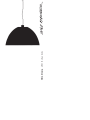
Ingo Maurer XXL Dome Istruzioni per l'uso
- Tipo
- Istruzioni per l'uso

XXL Dome LED Instructions

Montageanleitung
Bitte vor der Montage aufmerksam lesen und
aufbewahren!
Instructions for Assembly
Please read these instructions carefully before going
any further, and keep them in a safe place for future
reference!
Instructions de montage
A lire attentivement avant le montage et à conserver!
Istruzioni di montaggio
Prima del montaggio leggere attentamente le
istruzioni e conservarle!
1
XXL Dome
Ingo Maurer 1999 / 2018
2

Deutsch Seite 4
English Page 9
Français Page 14
Italiano Pagina 19
Zeichnungen Seite 24
Drawings Page 24
Dessins Page 24
Disegni Pagina 24
3
Montage und Elektroanschluss müssen von einer Elektro -
fachkraft ausgeführt werden. Wir empfehlen, die Montage
mit vier Personen durchzuführen.
XXL Dome ist ein handwerklich hergestelltes Produkt.
Abweichungen in Oberflächenstruktur, Größe oder Form
des Objekts sind herstellungstechnisch bedingt und ein
gewünschter Teil der Gestaltung.
Wichtig: Die Leuchte hat ein Gesamtgewicht von ca.
50 kg. Bitte überprüfen Sie die ausreichende Tragfähigkeit
der Decke. Achten Sie auf adäquate Befestigungsmittel
entsprechend der jeweiligen Deckenkonstruktion: es müssen
Schwerlastdübel aus dem Fachhandel verwendet werden.
Beachten Sie auch die örtlichen Sicherheitsvorschriften.
Achtung: Schalten Sie vor der Montage die Sicherung
des Deckenauslasses aus! Achten Sie unbedingt auf den
Verlauf von Elektroleitungen, damit auf keinen Fall ein
Kabel angebohrt wird. Montieren Sie nicht auf feuchtem
und leitendem Untergrund!
Auspacken
Achtung: Bitte tragen Sie schon beim Auspacken die mit-
gelieferten Handschuhe, da die matt lackierte Oberfläche
der Kuppelinnenseite äußerst empfindlich ist.
Die Transportkiste ist so gebaut, dass zuerst der Deckel und
dann alle vier Seiten nacheinander abgenommen werden
können. Die Kuppel sollte – noch auf der Bodenplatte
der Kiste stehend – mit einem Hubwagen zu der Stelle
gefahren werden, an der sie aufgehängt wird.
Wichtig: Es sind mindestens drei Personen notwendig,
um die Kuppel ohne Bodenplatte anzuheben oder zu tragen!
Andernfalls könnte sich die Kunststoffkante der Kuppel
verformen.
Deutsch
4

Deutsch
Montage des Baldachins
Achtung: Schalten Sie vor der Montage die Sicherung
des Deckenauslasses aus. Achten Sie unbedingt auf den
Verlauf von Elektroleitungen, damit auf keinen Fall ein
Kabel angebohrt wird. Montieren Sie nicht auf feuchtem und
leitendem Untergrund!
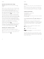
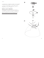
Legen Sie die Position des Baldachins (1) so fest, dass das
Kabel des Deckenauslasses durch die große Baldachinöffnung
ragt. Benutzen Sie den Baldachin als Schablone zum Mar-
kieren der Bohrlöcher. Fädeln Sie das Zuleitungskabel (4)
durch die große Öffnung und befestigen Sie den Baldachin
mit drei Schrauben und Schwerlastdübeln an der Decke. 1
Wichtig: Der Baldachin muss ein Gewicht von ca.
50 kg tragen. Wählen Sie der Deckenkonstruktion
entsprechendes Befestigungsmaterial mit ausreichender
Tragfähigkeit!
Schrauben Sie die Rändelmutter (2) vom Gewindebolzen in
der Mitte des Baldachins ab. Fädeln Sie das Aufhängeseil (5)
durch Rändelmutter (2) und Mittelloch der Abdeckschei-
be (3). 1
Bevor Sie die Kuppel an den Baldachin hängen, vergewissern
Sie sich bitte, dass alle drei Schrauben fest in der Decke
sitzen und sowohl die Decke als auch das verwendete Auf-
hängematerial in der Lage sind, das Gewicht der Kuppel zu
tragen.
Einbau des Aufhängegestells und der E-Montage
Die Montage des Aufhängegestells ist nur dann notwendig,
wenn mehrere “XXL Domes” gestapelt in einer Transport-
kiste geliefert werden.
Stellen Sie die Kuppel mit der kleinen Öffnung nach oben
vor sich auf zwei Tische o.ä., sodass Sie unter der Kuppel
stehen können.
5
Deutsch
Setzen Sie das dreiarmige Aufhängegestell (6) mit der
vormontierten Elektromontage (7) von unten in die
Kuppel ein. Beachten Sie die Markierungen (8) am
Aufhängegestell und dem mit der Kuppel verschraubten
Ring (9). Schrauben Sie das Aufhängegestell entsprechend
den Markierungen am Ring fest und legen Sie das Lampen-
kabel (10) außen über die Kuppel. 2
Aufhängen der Kuppel
Platzieren Sie die Kuppel unter dem bereits montierten
Baldachin und fädeln Sie das lose Ende des Seils durch
den Seilhalter (11) in der Mitte der Aufhängestruktur der
Kuppel. 3
Heben Sie die Kuppel mit mindestens drei Personen so
an, dass eine vierte Person darunter stehen kann, die das
Seil nachzieht. Bringen Sie die Kuppel auf die gewünschte
Höhe und ziehen Sie das Seil jeweils nach.
Achtung: Das Seil muss beim Nachziehen entlastet sein,
damit es sich nicht kräuselt und die Kuppel sich nach dem
Aufhängen nicht dreht!
Wir empfehlen, die Kuppel mindestens 2,20 m über den
Boden zu hängen. Falls die Höhe korrigiert werden muss,
kann der Seilhalter – bei entlastetem Seil – durch Druck
auf den Knopf (12) gelöst und die Höhe verstellt werden.
Wenn die endgültige Position erreicht ist, sichern Sie den
Seilhalter mit der Kontermutter (13). 3
Wichtig: Aus dem Seilhalter müssen immer mindestens
3 cm Restseil herausragen!
6

Elektroanschluss im Baldachin
Achtung: Schalten Sie die Sicherung des Deckenauslasses
aus.
Lassen Sie die abgemantelte Zuleitung des Deckenauslas-
ses (4) etwa 12 cm aus dem Baldachin ragen und isolieren
Sie die Enden der einzelnen Adern ca. 7 mm ab.
Schließen Sie Leiter und Neutralleiter auf der einen Seite
der Lüsterklemme (14) und den Schutzleiter am Erdungs-
nippel (15) entsprechend der Markierung im Baldachin
an. 4
Fädeln Sie das metallumhüllte Lampenkabel (16) durch
das außermittige Loch der Baldachin-Abdeckscheibe und
unter die Zugentlastungslasche (17). Ziehen Sie das Kabel
so weit in den Baldachin, dass es in weichem Bogen fällt
und schrauben Sie die Zugentlastung fest. Schneiden
Sie das Kabel ca. 10 cm hinter der Zugentlastung ab
und entfernen Sie die Metallumhüllung bis kurz vor
der Zugentlastungslasche. Bitte beachten Sie beim
Abmanteln des Kabels um ca. 4 cm, dass die empfindliche
Isolierung der Einzeladern nicht verletzt wird. Isolieren
Sie die Aderenden ca. 5 mm ab und verwenden Sie die
beiliegenden Aderendhülsen.
Schließen Sie den Schutzleiter mittig, Phase und Nullleiter
entsprechend der Markierungen in der Lüsterklemme (14)
an. 4
Schieben Sie die Abdeckscheibe (3) an Kabel und
Aufhängeseil nach oben und fixieren Sie sie mit der
Rändelmutter. 2
Einhängen des Sekundärreflektors
Fädeln Sie jeweils einen der Haken der 3 Haltedrähte
(25), von außen durch die Bohrungen im Rand des
Leuchtgehäuses (9).
Legen Sie dann den Sekundäreflektor (23) mit dem
äußeren Rand in die unteren Haken ein. 5
Deutsch
7
Pflege
Reinigen Sie die Außenseite der Kuppel mit einem
weichen Tuch.
Die farbige Innenseite der Kuppel und das silbern lackierte
Gehäuse der Lichtmontage können, nachdem sie vollständig
abgekühlt sind, mit einem weichen fusselfreien Tuch
trocken abgestaubt werden.
Technische Daten
220-240V 50Hz. 3 x 16,5W LED
110-130V 60Hz. 3x15W
100V 60Hz. 3x15W
Die für Ihre Leuchte zutreffende Spannung und Frequenz
entnehmen Sie bitte dem Typenschild.
3x 15 W LED, 0,87cosᵩ, 3x1300 lm, 3000 K, CRI>90.
Stufenlos dimmbar (siehe Geeignete Wanddimmer).
Mit eingebautem LED-Leuchtmittel, kann nicht vom Nutzer
ausgetauscht werden. Das Leuchtmittel darf nur von der
Ingo Maurer GmbH, einem von der Ingo Maurer GmbH
beauftragten Servicetechniker oder einer vergleichbar
qualifizierten Person ersetzt werden.
A+ Die Leuchte wird verkauft mit einem Leucht-
mittel der Energieklasse A+.
Vorsicht; Gefahr vor elektrischem Schlag
Jedes zerbrochene Schutzglas muss unbedingt
ersetzt werden.
Eventuell notwendige Reparaturen dürfen nur von einer
Elektrofachkraft durchgeführt werden. Die äußere Leitung
darf bei Beschädigung nur von der Ingo Maurer GmbH
ausgetauscht werden.
Deutsch
8

Bei Schäden, die durch Nichtbeachten dieser
Bedienungsanleitung, unsachgemäßer Inbetriebnahme und/
oder baulicher Veränderung z.B. durch Fremdbauteile,
Handhabung oder Fremdeingriff verursacht werden, erlischt
der Garantieanspruch.
Geeignete Wanddimmer
Die Leuchte kann mit einem speziellen Triac Dimmer
(Phasenanschnitt- und Phasenabschnittsteuerung) stufenlos
und fl immerfrei gedimmt werden. Aktuelle Empfehlungen
zu kompatiblen Dimmern entnehmen Sie bitte unserer
Internetseite: https://www.ingo-maurer.com/de/produkte/
xxl-dome
The lamp assembly and all electrical work must be carried
out by a qualified electrician. We recommend that at least
three further persons be available to help with the assembly.
XXL Dome is a hand-made product. Minor variations in the
surface structure, size and shape of the lamp are a natural
result of the production process and an intended design
feature.
Important: The lamp has a total weight of around 50
kg. Please make sure that your ceiling is capable of taking
the strain. Ensure that suitable fixing materials are used,
according to the ceiling construction: Heavy-duty ceiling
anchors, available from specialist retailers, must be used.
Local safety regulations must also be observed.
Caution: Switch off or remove the fuse for the ceiling
outlet before beginning the assembly. Please take care to
ascertain the exact position of all electrical wiring, so as to
avoid accidentally drilling into a cable. Do not attach the
lamp to a damp and/or conductive surface!
Unpacking the lamp
Caution: Please use the gloves supplied when unpacking
the lamp, as the matt-lacquered inner surface of the dome
is very easily damaged.
The shipping crate is constructed so that the lid is removed
first and then the four sides in succession, leaving the dome
on the base of the crate so that it can be moved with a
pallet jack to the exact site where the lamp is to be installed.
Important: At least three people are needed to lift or
carry the dome if it is removed from the base of the crate;
otherwise the plastic edge of the dome may become
damaged.
English
10
Deutsch
9

Assembling the canopy
Caution: Switch off or remove the fuse for the ceiling
outlet before beginning the assembly. Please take care to
ascertain the exact position of all electrical wiring, so as to
avoid accidentally drilling into a cable. Do not attach the
lamp to a damp and/or conductive surface!
Position the canopy (1) so that the mains cable from the
ceiling outlet protrudes through the large aperture in the
canopy. Use the canopy as a template to mark the drill
holes. Feed the mains cable (4) through the large aperture
and attach the canopy to the ceiling with three screws and
heavy-duty anchors. 1
Important: The canopy has to support a weight of around
50 kg. Ensure that the fixing materials are suited to the ceil-
ing construction and have sufficient load-bearing capacity.
Unscrew the knurled nut (2) from the spindle in the centre
of the canopy. Feed the suspension cable (5) through
the knurled nut (2) and the hole in the centre of the
cover (3). 1
Before hanging the dome on the canopy, please ensure
that all three screws are firmly anchored in the ceiling and
that the ceiling and the fixing materials are capable of
taking the weight of the dome.
Suspension frame and electrical assembly
The suspension frame is only required if several “XXL
Domes” are shipped together in a single crate.
Place the dome with the small aperture at the top on two
tables (or similar), so that you can stand under the dome.
Introduce the three-arm suspension frame (6) with the
pre-wired electrical assembly (7) into the dome from
below.
English
11
English
Note the markings (8) on the frame and the ring (9)
screwed into the dome. Screw the frame into place on the
ring according to the markings and lay the lamp cable (10)
on the top of the dome. 2
Attaching the dome
Place the dome under the previously assembled canopy
and thread the loose end of the suspension cable through
the cable holder (11) in the centre of the dome suspension
structure. 3
At least three people are required to lift the dome so
that a fourth person can stand underneath and adjust the
suspension cable. Lift the dome to the required height
and adjust the cable length accordingly.
Caution: When adjusting the height, please ensure that
the cable is not under strain, so that it does not become
twisted and the dome does not revolve after assembly.
The recommended suspension height for the dome is at
least 2.20 m above the floor. The height can be corrected
by pressing the button (12) on the cable holder (with the
cable slackened). Make the adjustment and secure the
cable holder with the counter-nut (13) when the required
position is reached. 3
Important: Always leave a spare length of cable (at least
3 cm) protruding from the cable holder!
12

Electrical connection in the canopy
Caution: Switch off or remove the fuse for the ceiling
outlet!
Remove a 12 cm section of the outer covering from the
mains cable (4) protruding through the canopy, and strip
about 7 mm from the ends of the three wires.
Connect the phase and neutral wires to the contacts on
the one side of the terminal (14) and attach the earth
wire to the earth contact (15) on the other, according to
the markings in the canopy. 4
Thread the metal-covered lamp cable (16) through the
off-centre aperture in the canopy cover and under the
strain relief (17). Pull the cable into the canopy so that it
falls in a loose arc and screw the strain relief down tightly.
Trim the cable about 10 cm from the strain relief and
remove most of the metal covering, leaving only a short
section just in front of the strain relief. When stripping the
cable approx. 4cm, please pay attention that the sensitive
insulation of the individual wires is not damaged.
Insulate the wire ends by approx. 5 mm and use the
enclosed wire end ferrules. 4
Fix the protective conductor centrally, phase and neutral
according to the markings in the luster terminal (3)
Push the cover (3) up along the lamp cable and suspen-
sion cable and attach it with the knurled nut. 2
Mounting the secondary reflector
Thread the hook (25) of the holding wires from the
outside through the holes in the edge of the light housing
(9).
Then insert the secondary reflector (23) with the outer
edge into the lower hooks. 5
English
13
English
Cleaning
The outer surface of the dome can be cleaned with a soft
cloth.
The coloured inner surface of the dome and the silver-
lacquered housing of the lamp fitting can be cleaned with
a dry soft cloth when they have cooled down completely.
Technical specification
220-240V 50Hz. 3 x 16,5W LED
110-130V 60Hz. 3x15W
100V 60Hz. 3x15W
The correct voltage and frequency for your lamp are indicated
on the type label.
3x 15 W LED, 201 mA, 0,87cosᵩ, 1300 lm, 3000 K, CRI>90.
Continuously dimmable (see Compatible wall dimmers,
below).
With built-in LEDs of energy class A+, which cannot be
replaced by the user. The light source of this lamp may only
be replaced by Ingo Maurer GmbH or a service technician
authorized by Ingo Maurer GmbH or a similar qualified
person.
A+ The lamp is supplied with an LED module of
energy class A+.
Caution; danger of electric shock
The protective glass cover must be replaced in
case of damage.
Any repairs that may become necessary must be carried
out by a professional electrician. In the event of damage to
the external power cord, replacements may only be fitted
by Ingo Maurer GmbH.
14

The legal and contractual warranty for defects and product
liability will be void, should the installation instructions not be
duly followed or non-original components be employed.
Compatible wall dimmers
The lamp can be connected to a special Triac (leading edge
or trailing edge phase control) dimmer for continuous and
fl icker-free operation. For current recommendations on com-
patible dimmers please see our website:
https://www.ingo-maurer.com/en/products/xxl-dome
Le montage et le branchement électrique sont à effectuer
par un électricien. Nous recommandons d’exécuter le
montage à quatre personnes.
XXL Dome est un produit confectionné à la main. Des
irrégularités dans la structure de la surface, la taille ou la
forme de l’objet sont dûes à la technique de production et
font partie du design.
Important: La lampe a un poids total d’env. 50 kg. Prière
de contrôler la limite de charge du plafond.Vérifiez que
les fixations soient adéquates à la construction du plafond:
il est absolument nécessaire d‘ utiliser des chevilles de grande
portée en vente dans le commerce. Prière de respecter
également les normes locales de sécurité.
Attention: déconnecter le fusible contrôlant l’arrivée du
courant au plafond avant le montage! Il est indispensable de
respecter le positionnement des conduites électriques pour
éviter de percer un câble électrique. Ne pas installer sur
une surface humide et/ou conductrice!
Déballage
Attention: prière de porter les gants joints lors du
déballage, le vernis mat de la surface intérieure de la
coupole est extrêmement sensible.
La caisse en bois est construite de telle façon que tout
d’abord le couvercle, puis les quatre côtés se démontent
l’un après l’autre. Placée encore sur la plaque de base
de la caisse, la coupole doit être transportée par chariot
élévateur à l’endroit où elle doit être suspendue.
Important: au moins trois personnes sont nécessaires
pour soulever ou porter la coupole sans la plaque de base!
Autrement, le bord en plastique de la coupole pourrait se
déformer.
Français
15 16
English

Montage du baldaquin
Attention: déconnecter le fusible contrôlant l’arrivée du
courant au plafond avant le montage! Il est indispensable
de respecter le positionnement des conduites électriques
pour éviter de percer un câble électrique. Ne pas installer
sur une surface humide et/ou conductrice!
Positionner le baldaquin (1) de telle manière à ce que
le câble de la sortie du plafond dépasse de la grande
ouverture du baldaquin. Utiliser le baldaquin comme
gabarit pour marquer les trous de perçage. Enfiler le
câble d’alimentation (4) par la grande ouverture et fixer
le baldaquin au plafond à l’aide de trois vis et chevilles de
grande portée. 1
Important: le baldaquin doit supporter un poids d’env.
50 kg. Choisir en conséquence le matériel de fixation corres-
pondant à la construction du plafond et ayant une limite
de charge suffisante.
Dévisser l’écrou moleté (2) du boulon fileté au milieu du
baldaquin. Enfiler le câble de suspension (5) au travers
de l’écrou moleté (2) et du trou central de la plaque de
recouvrement (3). 1
Avant de suspendre la coupole au baldaquin, s’assurer
que les trois vis sont bien fixées dans le plafond et que le
plafond comme le matériel de suspension utilisé soient
en mesure de supporter le poids de la coupole.
Installation du support de suspension et du
montage électrique
Le montage du support de suspension est nécessaire unique-
ment quand plusieurs ‘XXL Domes’ sont livrées positionnées
les unes dans les autres dans une caisse de transport.
Positionner devant soi la coupole avec la petite ouverture
vers le haut sur deux tables ou équivalent, de telle manière
à ce que l’on puisse se tenir sous la coupole.
Français
17
Français
Insérer le support de suspension (6) à trois bras avec le
montage électrique (7) prémonté par le dessous dans la
coupole. Observer les marquages (8) sur le support de
suspension et sur l’anneau (9) vissé à la coupole. Visser
fermement le support de suspension correspondant aux
marquages sur l’anneau et positionner le câble électrique
de la lampe (10) à l’extérieur, par dessus la coupole. 2
Suspension de la coupole
Placer la coupole sous le baldaquin déjà monté et enfiler
l’extrémité libre du fil par le porte-fil (11) au milieu de la
structure de suspension de la coupole. 3
Elever la coupole à l’aide d’au moins trois personnes afin
qu’une quatrième personne, chargée de tirer sur le fil, puisse
se tenir au-dessous. Positionner la coupole à la hauteur
souhaitée et tirer respectivement sur le fil.
Attention: avant de tirer sur le fil, vérifier qu’il est déchargé
de toute traction, afin qu’il ne s’effiloche pas et que la
coupole ne tourne pas sur elle-même, une fois suspendue!
Nous recommandons de suspendre la coupole au moins
à 2,20 m au-dessus du sol. Au cas où la hauteur devrait
être corrigée, il est possible de desserrer le porte-fil
– uniquement lorsque le fil est déchargé de traction – en
appuyant sur le bouton (12) et d’ajuster la hauteur. Une
fois la position finale atteinte, bloquer le porte-fil à l’aide
du contre-écrou (13). 3
Important: il faut toujours que 3 cm minimum de fil
dépassent du porte-fil!
18

Connexion électrique dans le baldaquin
Attention: déconnecter le fusible contrôlant l’arrivée du
courant au plafond!
Faire dépasser du baldaquin la conduite dégainée de la
sortie du plafond (4) d’environ 12 cm et dénuder les
extrémités de chaque fil conducteur d’environ 7 mm.
Connecter le fil de phase et le fil neutre à l’un des côtés
du domino (14) et le fil de terre au raccord de mise à la
terre (15) correspondant au marquage sur le baldaquin. 4
Enfiler le câble électrique (16) de la lampe recouvert de
métal au travers du trou central de la plaque de recouvre-
ment du baldaquin et sous la languette de décharge de
traction (17). Insérer le câble le plus loin possible dans le
baldaquin, afin qu’il retombe en formant un arc léger et
visser la décharge de traction. Couper le câble environ
10 cm derrière la décharge de traction et ôter le
revêtement métallique jusque devant la languette de
décharge de traction. Connecter les trois fils conducteurs
dénudés aux douilles encore libres du domino (14) selon
le marquage. 4
Déplacer la plaque de recouvrement (3) vers le haut sur
le câble et fil de suspension et fixer la à l’aide de l’écrou
moleté. 2
Montage du réflecteur secondaire
Enfiler un des crochets de chacun des 3 fils de retenue (25)
de l‘extérieur à travers les trous dans le bord du boîtier de
l‘éclairage (9).
Insérer ensuite le réflecteur secondaire (23) avec le bord
extérieur dans les crochets inférieurs.
Entretien
Nettoyer la surface extérieure de la coupole avec un chiffon
souple et le cas échéant avec un nettoyant doux sans déter-
gent.
Français
19
Français
Une fois complètement refroidis, la surface intérieure
colorée de la coupole et le boîtier verni argent du mon-
tage électrique peuvent être nettoyés avec un chiffon
souple et sec.
Données techniques
220-240V 50Hz. 3 x 16,5W LED
110-130V 60Hz. 3x15W
100V 60Hz. 3x15W
Veuillez consulter la plaque signalétique pour la tension et la
fréquence appropriée pour votre lampe.
3x 15 W LED, 0,87cosᵩ, 3x1300 lm, 3000 K, CRI>90.
Réglage en continu (cf Variateurs muraux compatibles).
Avec module LED intégré, ne peut pas être changée par
l‘utilisateur. Le module ne doit être remplacée que par la
société Ingo Maurer ou par un technicien commandité
par la société Ingo Maurer ou une personne ayant des
qualifi cations comparables.
A+ Cette lampe est équipée d‘un module LED intégré
de la classe énergétique A+.
Attention: danger d‘électrocution
Tout verre cassé doit être obligatoirement rem-
placé.
Des réparations éventuellement nécessaires ne doivent
être effectuées que par un spécialiste.
En cas d’endommagement, le câble électrique externe ne
doit être échangé que par la société Ingo Maurer GmbH.
La garantie légale et contractuelle pour les défauts et
la responsabilité pour les dommages causés par des
produits défectueux, expireront en cas de dommages ou
de réclamations résultant du non-respect des instructions
d‘installation et/ou des modifications structurelles, en
particulier si des composants non originaux sont utilisés.
20

Variateurs muraux compatibles
L’intensité de lumière de la lampe peut être réglée en con-
tinu et sans scintillement par un variateur Triac spécial
(commande à coupe de phase ascendante ou descendante).
Veuillez s‘il vous plaît consulter sur notre site Internet nos
recommandations actuelles sur les variateurs compatibles:
https://www.ingo-maurer.com/fr/produits/xxl-dome
Italiano
Il montaggio e il collegamento elettrico devono essere ese-
guiti da un elettricista specializzato. E’ consigliato effettuare
il montaggio in quattro persone.
XXL Dome è un prodotto realizzato a mano. Differenze
di struttura della superficie, dimensioni e forma sono
intenzionali e un naturale risultato del procedimento di
produzione.
Importante: Il lampadario ha un peso complessivo di ca.
50 kg. Si prega di controllare preventivamente la portata
sufficiente del soffitto. E’ importante provvedere a mezzi
di fissaggio adatti alla relativa costruzione del soffitto:
impiegare assolutamente tasselli per carichi pesanti in
vendita nei negozi specializzati. Rispettare anche le locali
norme di sicurezza.
Attenzione: Prima del montaggio staccare la corrente
dell’uscita della corrente al soffitto! Fare assolutamente
attenzione al percorso delle linee di alimentazione per
evitare di danneggiare un cavo durante la foratura. Non
montare su superfici umide o conduttrici di corrente!
Rimuovere dall’imballo
Attenzione: Indossare i guanti in dotazione già durante
l’apertura dell’imballo, per evitare di danneggiare la
superficie interna verniciata opaca estremamente delicata
della calotta.
L’imballo per il trasporto è concepito in modo che prima
viene rimosso il coperchio e di seguito le quattro pareti
una dopo l’altra. Si raccomanda di trasportare la calotta
– ancora appoggiata sul fondo dell’imballo – con un carrello
elevatore nel punto dove sarà appesa.
Importante: Sono necessarie almeno tre persone per
alzare o trasportare la cupola senza il fondo dell’imballaggio!
In caso contrario si potrebbe deformare il bordo della
calotta in materiale sintetico.
2221
Français

Italiano
Montaggio del rosone
Attenzione: Prima del montaggio staccare la corrente
dell’uscita di corrente al soffitto! Fare attenzione al percorso
delle linee di alimentazione per evitare di danneggiare un
cavo. Non montare su superfici umide e/o conduttrici di
corrente!
Determinare la posizione del rosone (1) in modo che il
cavo dell’uscita di corrente al soffitto passi attraverso l’aper-
tura maggiore del rosone. Impiegare il rosone come dima
di foratura per contrassegnare i punti da forare. Introdurre
il cavo di alimentazione (4) attraverso l’apertura maggiore
e fissare il rosone con tre viti e tasselli per carichi pesanti
al soffitto. 1
Importante: Il rosone deve sostenere un peso complessivo
di 50 kg circa. Scegliere, pertanto, un materiale di fissaggio
adatto alla costruzione del soffitto e avente una portata
sufficiente!
Svitare il raccordo zigrinato (2) dal perno al centro del
rosone. Infilare il cavo di sospensione (5) attraverso il
raccordo zigrinato (2) e il foro centrale del disco di coper-
tura (3). 1
Prima di appendere la calotta al rosone, accertarsi che tutte
e tre le viti siano saldamente fissate al soffitto e che sia il
soffitto che il materiale di sospensione impiegato siano in
grado di sostenere il peso.
Inserimento della struttura di sospensione
e dell’unità elettrica
Il montaggio della struttura di sospensione è richiesto
soltanto se più “XXL Dome” sono disposte in un unico
imballo.
Sistemare la calotta con il foro inferiore rivolto verso l’alto
davanti a sé sopra due tavoli (o simili) in modo che sia
possibile stare in piedi sotto la calotta.
23
Italiano
Inserire la struttura di sospensione (6) a tre braccia con
l’unità elettrica (7) premontata dal basso nella calotta.
Rispettare i punti contrassegnati (8) sulla struttura di
sospensione e sull’anello (9) avvitato alla calotta. Avvitare
la struttura di sospensione all’anello conformemente ai
punti contrassegnati e appoggiare il cavo della lampada (10)
esternamente sulla calotta. 2
Appendere la calotta
Sistemare la calotta sotto il rosone già montato e intro-
durre l’estremità libera del cavo attraverso il gripper ferma-
cavo (11) al centro della struttura di sospensione della
calotta. 3
Alzare la calotta in almeno tre persone in modo che la
quarta possa stare ritta al suo interno e tirare il cavo.
Portare la calotta all’altezza desiderata e regolare in cavo
conseguentemente.
Attenzione: Dopo averlo tirato, il cavo deve essere privo
di trazione per evitare che si attorcigli e che la calotta ruoti
dopo essere stata appesa!
Raccomandiamo di appendere la calotta a un’altezza di
almeno 2,20 m dal pavimento. In caso si rendesse necessario
correggere l’altezza è possibile – solo con il cavo privo di
trazione – sciogliere il gripper ferma cavo premendo il
bottone (12). Dopo aver raggiunto la posizione definitiva,
fermare il gripper con il controdado (13). 3
Importante: Il cavo deve assolutamente essere inserito
nel fermacavo almeno 3 cm!
24

Collegamento elettrico nel rosone
Attenzione: Staccare la corrente dell’uscita di corrente
al soffitto!
Lasciare spuntare la linea di alimentazione dell’uscita di
corrente al soffitto (4) di circa 12 cm dal rosone e spelare
le estremità dei singoli fili di circa 7 mm.
Collegare fase e neutro da un lato del morsetto (14) e
la terra al raccordo di terra (15) secondo l’indicazione sul
rosone. 4
Infilare il cavo della lampada con rivestimento in metallo
(16) attraverso il foro non centrale del disco di copertura e
sotto il passante dello scarico di trazione (17). Introdurre il
cavo nel rosone assicurandosi che formi un leggero arco e
avvitare saldamente lo scarico di trazione.
Accorciare il cavo di ca. 10 cm la calotta dalla parte
retrostante allo scarico di trazione e rimuovere il
rivestimento in metallo fin poco antistante allo scarico di
trazione. Quando si spoglia il cavo circa 4cm, prestare
attenzione che l‘isolamento sensibile dei singoli fili non
sia danneggiato. Isolare le estremità dei fili di ca. 5 mm
e utilizzare il tasto capicorda a filo chiuso. Chiudere
il conduttore di protezione a livello centrale, di fase
e neutro alle boccole ancora libere del morsetto (3)
secondo le indicazioni. 4
Far scorrere il disco di copertura (3) lungo il cavo e
il cavetto di sospensione verso l’alto e fissarlo con il
raccordo zigrinato. 2
Montaggio del riflettore secondario
Infilare uno dei ganci di ciascuno dei 3 fili di fissaggio (25)
dall‘esterno attraverso i fori sul bordo dell‘alloggiamento
della lampada (9).
Inserire quindi il riflettore secondario (23) con il bordo
esterno nei ganci inferiori. 5
Italiano
25
Italiano
Cura
Pulire la superficie esterna della calotta in alluminio con
un panno morbido.
La superficie interna colorata della calotta e il contenitore
verniciato d’argento dell’unità elettrica possono essere puliti,
dopo essere completamente freddi, con un panno morbido
asciutto anti-pelucchi.
Dati tecnici
220-240V 50Hz. 3 x 16,5W LED
110-130V 60Hz. 3x15W
100V 60Hz. 3x15W
I dati tecnici relativi alla tensione e alla frequenza di
funzionamento della Vostra lampada sono riportati sulla
targhetta d’identificazione.
3x 15 W LED, 0,87cosᵩ, 3x1300 lm, 3000 K, CRI>90.
Regolazione continua dell’intensità luminosa (vedi Dimmer
a parete compatibili).
Con modulo LED integrato, non può essere sostituito
dall‘utente. Il modulo LED può essere sostituito esclusiva-
mente dalla Ingo Maurer GmbH, oppure da un tecnico
specializzato incaricato dalla Ingo Maurer GmbH oppure da
un persona ugualmente qualifi cata.
A+ La lampada è munita di un LED integrato della
classe energetica A+.
Attenzione; pericolo di scossa elettrica
Ogni vetro di protezione danneggiato deve essere
assolutamente sostituito.
Eventuali riparazioni possono essere effettuate esclusiva-
mente da un elettricista. Il cavo esterno – se danneggiato –
può essere sostituito soltanto dalla Ingo Maurer GmbH.
26

La garanzia legale e contrattuale per difetti e la responsabilità
per danni da prodotti difettosi, decadono in caso di danni
o reclami conseguenti all’inosservanza delle istruzioni
d’installazione e/o a modifiche strutturali, soprattutto se
impiegati componenti non originali.
Dimmer a parete compatibili
L’intensità luminosa può essere regolata di continuo e
senza sfarfallìo con un dimmer Triac speciale (a taglio di fase
ascendente/ discendente). Per attuali raccomandazioni su
dimmer compatibili, si prega di consultare il nostro sito:
https://www.ingo-maurer.com/it/prodotti/xxl-dome
27
Italiano
1
2
2
3
5
4
1
6
7
10 8
9
3
28

3
4
min. 3 cm
12
11 13
4
14
16
17
15
29

Ingo Maurer GmbH
Kaiserstrasse 47
80801 München
Germany
T. +49. 89. 381606-0
F. +49. 89. 381606 20
www.ingo-maurer.com
März 2019 Made in Germany
-
 1
1
-
 2
2
-
 3
3
-
 4
4
-
 5
5
-
 6
6
-
 7
7
-
 8
8
-
 9
9
-
 10
10
-
 11
11
-
 12
12
-
 13
13
-
 14
14
-
 15
15
-
 16
16
-
 17
17


Ingo Maurer XXL Dome Istruzioni per l'uso
- Tipo
- Istruzioni per l'uso
in altre lingue
Documenti correlati
-
Ingo Maurer Pierre ou Paul Istruzioni per l'uso
-
-
-
-
-
-
-
-
-