STUDIO DUE CITYCOLOR LED RGBW Manuale utente
- Categoria
- Stroboscopi
- Tipo
- Manuale utente

User manual for art.1302/E
Manuale d’uso per art.1302/E

2
rel.6 - 04/20 - Studio Due
!
WARNING
IMPORTANTE
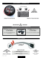
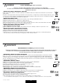
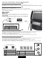
4 PIN connector - Connettore 4 PIN
NIP SIGNAL
1GROUND/RETURN/OV
N.C.
2
DATA COMPLEMENT ( -, INVERTED)
3
4 or DATATRUE ( +, NON INVERTED)
MALEFEMALE
4 or 1
14 or
23
32
4 PIN connectors
art. 4 PIN/XLR MF
(OPTIONAL)
INDOOR USE ONLY
!WARNINGIMPORTANTE
art. 4 PIN/XLR MF male/female connectors
(optional)
art. 4 PIN/XLR MF connettori maschio/femmina
(opzionale)
these
CONNECTORS
are for INDOOR use
only
these
CONNECTORS
are IP67
questi connettori sono
solo per uso INTERNO questi connettori
sono IP67
,I\RXZDQWWRFRQQHFWWKH¿[WXUHVIRU
OUTDOOR use, you can make a new
cable utilizing the
art. 4 PIN-CONN M/F
The cable is not endowed with the
connectors kit
Se volete utilizzare gli apparecchi
all’ESTERNO, potete realizzare dei
nuovi cavi con
art. 4 PIN-CONN M/F
Il cavo non è incluso nel kit dei connettori
art. 4 PIN-CONN M/F
HQGRZHGZLWKWKH¿[WXUHLQFOXVRQHOO¶DSSDUHFFKLR
RSWLRQDORS]LRQDOH
,QWKLVFRQQHFWRU\RXFDQ¿QGWKH
NUMBER 4 or the GROUND sign. In questo connettore potete trovare il
NUMERO 4 o il simbolo della TERRA.

3rel.6 - 04/20 - Studio Due
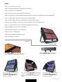
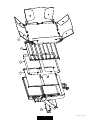
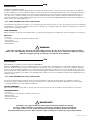
CityColor LED
The Citycolor LED with the optional
art. CCLED-FRH (frame holder) +
the optional art. CCLED-AG 2 pcs.
(anti glare) mounted.
The optional art. CCLED-FRH (frame holder)
+ optional art. CCLED-BD 4 pcs. (barn door
with extension) to define the illuminated
surface.
The Citycolor LED with the optional
art. CCLED-FRH (frame holder) +
the optional art. CCLED-AG 2 pcs.
(anti glare) mounted.
Art. CCLED-FROST. Optional kit wide beam
(2 pcs.) to increase the light beam up to 65°.
Optional
Art. CCLED-AD BOX, is the optional
XRL + Powercon adapter box (IP20).
INDEX
Page 4 - Accessories / Accessori
Page 10 - Safety informations / Informazioni di sicurezza
Page 11 - Introduction / Introduzione
Page 12 - Technical features / Caratteristiche tecniche
Page 13 - Example of connection DMX controller-fixtures / Esempio di collegamento centralina DMX-fari
Page 13 - DMX signal connection / Collegamento segnale DMX
Page 14 - Main supply connection / Collegamento fonte di alimentazione
Page 15 - Rear view fixture connections / Vista posteriore connessioni apparecchio
Page 17 - Control panel functions / Funzioni del pannello di controllo
Page 22 - DMX Listing / Lista dei canali DMX
Page 26 - Built in programs / Lista dei giochi
Page 27 - Physical / Dimensioni
Page 29 - CE standards / Certificazioni CE
Page 31 - Warranty / Garanzia

4
rel.6 - 04/20 - Studio Due
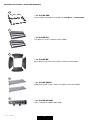
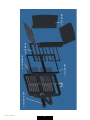
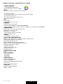
- art. CCLED-FRH
frame holder required for assembly of anti glare and barn door
- art. CCLED-AG
anti glare kit (2 pcs.) without frame holder
- art. CCLED-BD
barn door kit with extension (4 pcs.) without frame holder
- art. CCLED-FROST
wide beam kit 65° (2 pcs.) does not require the frame holder
- art. CCLED-AD BOX
XRL + Powercon adapter box (IP20)
OPTIONAL ACCESSORIES / ACCESSORI OPZIONALI
1
2
3
4
5

5rel.6 - 04/20 - Studio Due
5
4 1 23

6
rel.6 - 04/20 - Studio Due
art. CCLED-FROST
art. CCLED-FRH
art. CCLED-AG
art. CCLED-BD
art. CCLED-AD BOX

7rel.6 - 04/20 - Studio Due
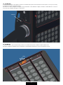
art. CCLED FRH
To fix the frame holder to the fixture, position it as shown in the picture and screw the 4 screws. This accessory is necessary
to install the anti glare and the barn door.
Per fissare la cornice di supporto all’apparecchio posizionarlo come illustrato in figura e avvitare le 4 viti. Questo accessorio e
necessario per installare l’anti glare e il barn door.
click
screws
art. CCLED AG
To fix the anti glare on the frame holder, position it as shown in the picture, slide the retainer until it locks.
Per fissare l’anti glare all’apparecchio posizionarlo come illustrato in figur, fare scorrere il fermo fino al click.

8
rel.6 - 04/20 - Studio Due
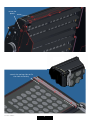
screw the
pawls
stretch the spring clips to fix
the frost accessory
A(1:1)

9rel.6 - 04/20 - Studio Due
this page is intentionally left blank

10
rel.6 - 04/20 - Studio Due
eng
WARNING
!SAFETY INFORMATION (service personnel)
READ ALL CAUTIONS AND WARNINGS PRIOR TO OPERATE THIS EQUIPMENT.
INSTRUCTION TO PREVENT INJURY OR DAMAGE DUE TO ELECTRIC SHOCK, FIRE, MECHANICAL HAZARDS,
DANGEROUS MATTERS.
•PROTECTION AGAINST FIRE
1) Maintain minimum distance of 0.2 meter from walls or any other type flammable surfaces.
2) Maintain minimum distance of 0,2 meter to lighted objects .
3) Replace fuses (if present) only with the specified type and rating.
4) Do not install the fixture close to heat sources. Do not lay the connection cable on the fixture when it is warm.
5) Fixture designed to be installed on normally flammable surfaces.
•PROTECTION AGAINST ELECTRIC SHOCK
1) This equipment must be earthed.
2) Class I equipment. The power supply cord includes a protective earthing conductor as part of the cord.
3) Disconnect power before servicing (service personnel).
•PROTECTION AGAINST MECHANICAL HAZARDS
1) Use secondary safety chain when fixing this equipment.
2) Equipment surface may reach temperature up to 75°C.
3) The protection screens and the lenses must be replaced with genuine parts only if they are visibly damaged and
their effectiveness has been reduced, for example, by cracks or deep scratches.
•PROTECTION AGAINST DANGEROUS MATTERS
At the end of its life, must be collected separately. It shouldn’t be thrown as urban waste and neither released in the
environment.
It must be collected from the nearest special waste collection point or consigned to your dealer that provides the servi-
ce. The incorrect waste disposal can damage the environment and the people for the presence of dangerous substan-
ces. Sanctions are provided for an unauthorized disposal.
F
INFORMAZIONI DI SICUREZZA (personale di servizio)
LEGGERE ATTENTAMENTE TUTTI GLI AVVERTIMENTI PRIMA DI COMPIERE QUALUNQUE OPERAZIONE SU QUESTO
APPARECCHIO. ISTRUZIONI PER PREVENIRE LESIONI O DANNI DOVUTI AL FUOCO, ALLE SCOSSE ELETTRICHE,
AI RISCHI MECCANICI ED A SOSTANZE PERICOLOSE.
•PROTEZIONE CONTRO IL FUOCO
1) Mantenere la distanza minima di 0.2 metri da pareti ed altre superfici infiammabili.
2) Mantenere la distanza minima di 0,2 metri dagli oggetti illuminati.
3) Sostituire i fusibili (se presenti) solo con altri dello stesso tipo e valore.
4) Non installare l’apparecchio vicino fonti di calore.
Non appoggiare il cavo di connessione sul faro quando questo è caldo.
5) Questo apparecchio è adatto per il montaggio su superfici normalmente infiammabili.
•PROTEZIONE CONTRO SCOSSE ELETTRICHE
1) Questo apparecchio necessita di messa a terra.
2) Apparecchio di Classe I. Il conduttore di protezione deve far parte del cavo di alimentazione.
3) Disconnettere l’alimentazione prima di aprire l’apparecchio (personale di servizio).
•PROTEZIONE CONTRO RISCHI MECCANICI
1) Usare la catena di sicurezza supplementare quando installate l’apparecchio.
2) La temperatura dell’apparecchio può raggiungere 75°C.
3) Gli schermi di protezione e le lenti devono essere sostituiti sempre con ricambi originali
se sono visibilmente danneggiati e se la loro efficacia è stata ridotta, per esempio, da fessure o incisioni profonde.
IMPORTANTE
!
•PROTEZIONE CONTRO SOSTANZE PERICOLOSE
A fine vita è oggetto di raccolta separata, non gettare nei comuni cassonetti di rifiuti urbani, né tantomeno nell’am-
biente. Può essere consegnato presso gli appositi centri di raccolta differenziata predisposti dalle amministrazioni
comunali, oppure presso i rivenditori che forniscono questo servizio. Lo smaltimento errato può causare danni alle
persone e all’ambiente per la possibile presenza di sostanze pericolose. Sono previste sanzioni in caso di smaltimen-
to abusivo dei suddetti prodotti.
F
0,2 m
ita
0,2 m
IP67
IP67

11 rel.6 - 04/20 - Studio Due
WARNING
!
Check that the fixture has not been damaged during transport. If it has been damaged or it does not work,
address the seller. Whether the fixture has been shipped to you directly, please contact the shipping company.
Only the consignee (person or company) can claim for these damages.
INTRODUCTION
Thanks for using CityColor LED.
The CityColor LED is a new IP67 lighting fixture, designed with unique features. Incorporates all the advantages of the LED tech-
nology combined in an renewed aesthetic. Wireless ready. Conceived for outstanding installations, for the architectural market as
well as for the entertainment business, the new generation of CityColor is the ideal solution to light up large facades, large con-
certs, big events, commercial malls, skyscrapers, public buildings, bridges, parks, public monuments and themed attractions.
The product with levels of light output and projection never before achieved in an LED lighting fixture, gives new possibilities for
outdoor and indoor lighting applications.
• Art. 1302/E RGBW/FC (full color) CityColor LED
To obtain the best performances and for a correct functioning of this unit for the years to come, we suggest you to read carefully this
manual before connecting or putting the fixture into use. By doing so you will gain experience with its commands and connections
and you will be easily able to use it.
YOUR REFERENCE
Always remember to give the serial number and to specify the model any time you address the seller for information or assistance.
BASIC KIT
• Projector
• n.2 connectors 4 pin male and female (without cable)
• User manual
• Studio Due warranty
• CE standards
INTRODUZIONE
Vi ringraziamo per l’ utilizzo del nostro CityColor LED RGB/FC.
Il CityColor LED RGB/FC è un nuovo cambiacolori IP67 che racchiude tutti i vantaggi della tecnologia LED combinata ad un look
rinnovato. Wireless ready. Concepito per installazioni eccezionali, per il mercato architettonico, nonché per l’attività di intratteni-
mento, la nuova generazione di CityColor è la soluzione ideale per illuminare grandi facciate, concerti, grandi eventi, centri com-
merciali, grattacieli, edifici pubblici, ponti, parchi, monumenti pubblici e attrazioni a tema. Il prodotto ha livelli di emissione di luce
e proiezione mai raggiunto in un apparecchio di illuminazione a LED e offre nuove possibilità per applicazioni di illuminazione per
interni ed esterni.
• Art. 1302/E RGBW/FC (full color) CityColor LED
Per ottenere il meglio delle prestazioni ed un corretto funzionamento negli anni di questa unità, Vi consigliamo di leggere
attentamente questo manuale prima di collegarla e metterla in uso. In questo modo acquisirete familiarità con i suoi comandi
e collegamenti affinché possiate utilizzarla facilmente.
VOSTRA REFERENZA
Citate sempre il numero del modello e di serie ogni volta che Vi rivolgete al vostro rivenditore per informazioni o assistenza.
CONFEZIONE BASE
• Proiettore
• n.2 connettori a 4 pin maschio e femmina (senza cavo)
• Manuale d’uso
• Garanzia Studio Due
• Dichiarazione CE
Controllate che l’apparecchio non abbia subito alcun danno durante il trasporto.
Se avesse subito dei danni o se non dovesse funzionare, rivolgetevi al vostro rivenditore.
Se l’apparecchio vi è stato spedito direttamente, rivolgetevi subito alla ditta di trasporto.
Solo il destinatario (la persona o ditta ricevente l’apparecchio) può reclamare per questo tipo di danni.
IMPORTANTE
!
eng
ita

12
rel.6 - 04/20 - Studio Due
TECHNICAL FEATURES / CARATTERISTICHE TECNICHE
• SOURCE RGBW/FC
n. 120 (5050-20W-RTBH) LEDs
power of driving all color on: 610W
• OPTIC
8°, 15°, 25°, 40°, 60°, 10ºx30º (38 mm lenses)
Accessories optional
- Frame holder (required to mount barn-door and anti-glare)
- 65° plan-filter (kit 2 pcs.)
- Barn-door with extensions (kit 4 pcs.)
- Anti-glare (kit 2 pcs.)
• TILT
Manual 240°
2 adjustable heads +9° each
• CONTROL
Standard interface: RS-485
Protocol: USITT DMX512 - RDM - DMX-RDM/DRS
- Integral Wireless DMX control (receiver) is available as an option (art. WI PCB-REC)
• CONNECTIONS
Signal: 4pin IP 67 connector (male-female)
Main Power: 3x1,5mm cable
Available as accessories:
- XLR 3/5pin+Powercon in-out box
- Wireless DMX receiver
• SAFETY
n. 4 eyebolts for safety chains
• SETUP AND CONFIGURATION
RDM control/configuration or by DRS (remote control device)
Control panel with touch technology
Led display with flip function
Dedicated DMX channel for white balance
DMX or Auto mode with Master-Slave function
Intelligent temperature control
Flicker-free function
Smooth dimming function
Halogen simulation
CYM simulation
• RATING PROTECTION
IP 67
• DMX CHANNELS
- 9CH mode
- 5CH mode
- 4CH mode
• POWER SUPPLY
Rated voltage 100-240V~
Frequency 50-60Hz
Rated current 2,8A@230V-Fuse T10A
Active PFC
Power consumption 650W
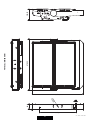
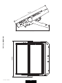
• PHYSICAL
WxDxH: 680x145x640 mm
Weight: 32 Kg.

13 rel.6 - 04/20 - Studio Due
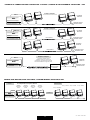
EXAMPLE OF CONNECTION DMX CONTROLLER - FIXTURES / ESEMPIO DI COLLEGAMENTO CENTRALINA - FARI
DMX
¿[WXUH ¿[WXUH ¿[WXUH ¿[WXUH
TL
NORMAL
$GGUHVV
VHWXSFK
=C001
$GGUHVV
VHWXSFK
=C010
$GGUHVV
VHWXSFK
&
$GGUHVV
VHWXSFK
=C027
¿[WXUH ¿[WXUH ¿[WXUH
TL
MASTER/SLAVE
6HWXS 0$67(5
VHWXS 6/$9( VHWXS 6/$9( VHWXS 6/$9(
¿[WXUH
NORMAL AND MASTER/SLAVE FUNCTIONS / FUNZIONI NORMAL E MASTER/SLAVE
Example 1/ Esempio 1
DMX
/DVW¿[WXUH
8OWLPRIDUR
7HUPLQDWLRQUHVLVWRU
7HUPLQDOHGLOLQHD
Example 2 / Esempio 2
DMX
/DVW¿[WXUH
8OWLPRIDUR
7HUPLQDWLRQUHVLVWRU
7HUPLQDOHGLOLQHD
OLQHOLQHD
7HUPLQDWLRQUHVLVWRU
7HUPLQDOHGLOLQHD
OLQHOLQHD
'0;RXW '0;RXW
&RQQHFWLRQFRQWUROOHUVSRWWR
'0;RXWSXWRYHUPWORQJ
&ROOHJDPHQWRFHQWUDOLQDVSRWDGXQDVROD
OLQHDGLXVFLWD'0;OXQJDROWUHPW
/,1(!PWZLWKPLFURSKRQLFRUDXGLRFDEOH
/,1($!PWFRQFDYRPLFURIRQLFRRDXGLR
DMX
7HUPLQDWLRQUHVLVWRU
7HUPLQDOHGLOLQHD
Example 3 / Esempio 3
6,*1$/$03/,),(5
$03/,),&$725(
',6(*1$/(
/DVW¿[WXUH
8OWLPRIDUR
/DVW¿[WXUH
8OWLPRIDUR
'0;RXW
'0;RXW
TL=
7HUPLQDO/LQH
IRUH[DPSOH¿[WXUHVHWXSDWFKDQQHOV
TL
TL
TL
TL

14
rel.6 - 04/20 - Studio Due
CONNECTION TO THE MAIN POWER / CONNESSIONE ALLA RETE ELETTRICA
This equipment must be earthed.
Class I equipment. The power supply cord includes a protective earthing conductor as part of the cord.
IMPORTANT: to ensure the IP67 protection rating, in case of replacement of the conductor cable, refer to the CONDUCTOR SIZE TABLE
Questo apparecchio necessita di messa a terra.
Apparecchio di Classe I. Il conduttore di protezione deve far parte del cavo di alimentazione.
IMPORTANTE: per garantire il grado di protezione IP67, in caso di sostituzione del cavo di alimentazione, fare riferimento alla
TABELLA SEZIONE CONDUTTORE.
eng
ita
DMX TERMINAL LINE
The wrong connection of the terminal line or its non-connection are probably the most frequent reasons for the defective functioning
of the DMX line. The terminator is a terminal resistor fitted at the end of the cable furthest from the transmitter.
The terminal resistor should have the same value as the impedance of the connection cable.
We suggest to use a terminal with a 120 Ohm resistor.
It is recommanded that all DMX 512 systems have the terminal resistor fitted in the DMX output of the last fixture.
TERMINALE LINEA DMX
L’incorretto o il mancato collegamento del terminale di linea è probabilmente la più comune causa del difettoso funzionamento
della linea DMX. Il terminale di linea DMX consiste in una resistenza posta alla fine della linea.
La resistenza terminale dovrebbe avere idealmente lo stesso valore dell’impedenza del cavo di collegamento.
Noi consigliamo di usare come terminale una resistenza da 120 Ohm.
E’ raccomandato per tutti i sistemi DMX 512 inserire il teminale di linea nel connettore uscita DMX dell’ultimo apparecchio collegato.
eng
ita
WARNING
!
HIGH VOLTAGE!
Always disconnect the mains supply before access to the connection area.
ALTA TENSIONE!
Scollegare sempre l’alimentazione prima di aprire il vano dei collegamenti.
Main IN
Yellow/Green
Blue Neutral
100/240V.~ - 50/60Hz
Brown
UNIVERSAL MAIN VOLTAGE
100-240V.~ / 50-60Hz
Termination resistor
Terminale di linea
120 Ohm
PIN LANGISERIW
NIP SIGNAL
1
1
SHIELD GROUND/RETURN/OV
GROUND/RETURN/OV
N.C.
2)DETREVNI,-(TNEMELPMOCATADROTCUDNOCRENNI
2
DATA COMPLEMENT ( -, INVERTED)
3
3
4
or
INNER CONDUCTOR DATATRUE ( +, NON INVERTED)
DATATRUE ( +, NON INVERTED)
DMX inputDMX output Termination resistor
Terminale di linea
120 Ohm
Termination resistor
Terminale di linea
120 Ohm
DMX input
MALEFEMALE
4 or
4
1
1
3
4 or
23
32
DMX output
4 PIN connectors
MAIN IN
Ingresso rete
CONDUCTOR SIZES / SEZIONE CONDUTTORE
(length / lunghezza < 20mt.)
MAINS VOLTAGE CROSS SELECTIONAL AREAS
230V 3X1 mm2 (minimum)
POWER INPUT/
INGRESSO ALIMENTAZIONE Ø 6 - 12mm

15 rel.6 - 04/20 - Studio Due
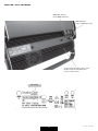
DMX IN (male)
Ingresso DMX (maschio)
DMX OUT (female)
Uscita DMX (femmina)
REAR VIEW / VISTA POSTERIORE
Cooling fan grids (always keep clean) /
Griglie ventole di raffreddamento
(tenere sempre pulite)
61

16
rel.6 - 04/20 - Studio Due
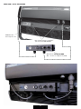
REAR VIEW / VISTA POSTERIORE
Optional art. CCLED-AD BOX:
XRL + Powercon adapter box (IP20)
Unscrew two knobs to install the
optional art. CCLED-AD BOX
MAIN IN cable
Cavo Ingresso rete

17 rel.6 - 04/20 - Studio Due
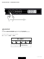
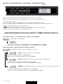
BUTTON FUNCTIONS - FUNZIONI DEI PULSANTI
UNLOCK sequence
1--- / -2-- / --3- / ---4 To enter the menu
Per entrare nel menù
ESC / UP / DOWN / ENTER
ESC DOWNUP ENTER
1° 2° 3° 4°
DMX led
If you want to enter into setup mode, you must follow the start procedure:
Se desiderate entrare nella modalità setup, dovete seguire la procedura di accesso:
Press keys in sequence / Premere i tasti in sequenza:
ESC >> UP >> DOWN >> ENTER
IMPORTANT
!

18
rel.6 - 04/20 - Studio Due
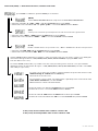
Switching on the fixture you can see the model and the software version. For example:
All’accensione, viene visualizzato il modello di apparecchio e la versione software. Per esempio:
--> Citycolor LED --> 1_00
than it’s shown the first DMX channel. When you press any button it’s shown the first menu.
poi viene visualizzato il primo canale DMX. Quando si preme qualsiasi pulsante, viene visualizzato il primo menu.
• UP: scroll up into the menu / scorre in alto nel menu
• DOWN: scroll down into the menu / scorre in basso nel menu
• ENTER: enter into the menu/submenu (if present) / entra nel menu/sottomenu (se presente)
• ESC: exit from the menu/submenu / esce dal menu/sottomenu
menu Address (Addr) > Set the DMX address / Imposta l’indirizzo DMX
press ENTER / premere ENTER
> Select the channel number .. c001 .. c002 .. with the UP/DOWN buttons. Press ENTER.
> Selezionate il canale desidarato .. c001 .. c002 .. con i tasti UP/DOWN. Premere ENTER.
menu Display (dISP) > Display functions / Funzioni del display
press ENTER for submenu / premere ENTER per i sottomenu
(FLIP) 180° display rotate / Ruota di 180° il display
> Select the value off .. on with the UP/DOWN buttons.
> Selezionate il valore desiderato off .. on con i tasti UP/DOWN.
(brGt) Display brightness settings / Impostazioni luminosità del display
> Select the value 1 .. 7 with the UP/DOWN buttons. Press ENTER.
> Selezionate il valore desidarato 1 .. 7 con i tasti UP/DOWN. Premere ENTER.
(LdMM) Power LEDS dimmer (with active menu) / Dimmer potenza dei LEDS (con menu attivo)
> Select the value off .. on with the UP/DOWN buttons. Press ENTER.
> Selezionate il valore desidarato off .. on con i tasti UP/DOWN. Premere ENTER.
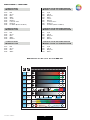
MENU LIST and BUTTON FUNCTIONS - ELENCO MENU’ e FUNZIONI DEI PULSANTI
When the display flashing you always must press and hold 1 sec. ENTER to confirm the selected option.
Quando il display lampeggia dovete sempre tenere premuto per 1 sec. ENTER per confermare l’opzione scelta.
DMX led

19 rel.6 - 04/20 - Studio Due
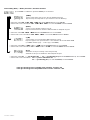
menu Auto (AUto) > Auto mode functions / Funzioni auto mode
press ENTER for submenu / premere ENTER per i sottomenu
(Mode)
Set the DMX/SLAVE/MASTER mode / Imposta la modalità DMX/SLAVE/MASTER
> Select the value no .. sl .. pr01 .. pr02 .. with the UP/DOWN buttons. Press ENTER.
> Selezionate il valore desidarato no .. sl .. pr01 .. pr02 .. con i tasti UP/DOWN. Premere ENTER.
(SPd)
Set the preset execution speed / Imposta la velocità di esecuzione dei giochi interni
> Select the value +400% .. -400% with the UP/DOWN buttons. Press ENTER.
> Selezionate il valore desiderato +400% .. -400% con i tasti UP/DOWN. Premere ENTER.
(ScnE)
Enable or disable the use of a personal scene / Abilia o disabilita l’uso di una scena personale.
> Select the value ON .. OFF with the UP/DOWN buttons. Press ENTER.
> Selezionate il valore desiderato ON .. OFF con i tasti UP/DOWN. Premere ENTER.
If menu SCENE (ScnE) is enabled, it is possible to create a personal scene (you can create a custom color utilizing the
menu which will appear below > RED, GREEN, BLUE, WHITE, WHITE BALANCE, varying the DMX values
from 0 to 255 for each color)
Se il menu SCENE (ScnE) è attivo, è possibile creare una scena personale (potete creare un colore personalizzato
utilizzando i menu che appariranno di seguito > RED, GREEN, BLUE, WHITE, WHITE BALANCE, variando i valori DMX
da 0 a 255 per ogni colore)
> Select the single color with the UP/DOWN buttons. Press ENTER.
> Selezionate il colore con i tasti UP/DOWN. Premere ENTER.
> Select the value 0 .. 255 with the UP/DOWN buttons. Don’t press ENTER.
> Selezionate il valore desiderato 0 .. 255 con i tasti UP/DOWN. Non premere ENTER.
For each color or menu it is possible to varying and than set-up the value from 0 to 255
without having to confirm with the ENTER key.
These functions are auto-save.
Per ogni singolo colore o menu, è possibile variare e quindi impostare il valore da 0 a 255
senza dover confermare con il tasto ENTER.
Queste funzioni si salvano automaticamente.
ScnE (scene) menu available from software version 2.00
ScnE (scene) menu disponibile dalla versione software 2.00

20
rel.6 - 04/20 - Studio Due
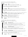
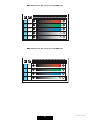
menu Utility (UtIL) > Utility functions / Funzioni di utilità
press ENTER for submenu / premere ENTER per i sottomenu
(SMth)
Set the interpolation type for the smooth dimming function
Imposta il tipo di interpolazione per la funzione smooth dimming
> Select the value oFF .. LoW .. MId .. hIGh with the UP/DOWN buttons. Press ENTER.
> Selezionate il valore desidarato oFF .. LoW .. MId .. hIGh con i tasti UP/DOWN. Premere ENTER.
(hALo)
Set the alogen simulation function mode
Imposta il funzionamento della modalità simulazione lampada alogena
> Select the value oFF .. MId1 .. MId2 with the UP/DOWN buttons. Press ENTER.
> Selezionate il valore desiderato oFF .. MId1 .. MId2 con i tasti UP/DOWN. Premere ENTER.
(cyM)
Set the fixture to work in CYM or RGB emulation system
Imposta l’apparecchio per funzionare come emulatore di sistema CYM o RGB
(see DMX channels page - vedere pag. canali DMX)
> Select the value off >> RGB or on >> CYM with the UP/DOWN buttons. Press ENTER.
> Selezionate il valore desiderato off >> RGB or on >> CYM con i tasti UP/DOWN. Premere ENTER.
(P-ht)
Simulation of the pre-heating of the halogen lamp
Simulazione del pre riscaldamento della lampada alogena
> Select the value off >> pre-heating off --- on >> pre-heating on (with the UP/DOWN buttons). Press ENTER.
> Selezionate il valore desiderato off >> preriscaldamento off ----
on >> pre-heating on (con i tasti UP/DOWN). Premere ENTER.
P-HT (pre-heating) menu available from software version 1.0.4
P-HT (pre-heating) menu disponibile dalla versione software 1.0.4
La pagina sta caricando ...
La pagina sta caricando ...
La pagina sta caricando ...
La pagina sta caricando ...
La pagina sta caricando ...
La pagina sta caricando ...
La pagina sta caricando ...
La pagina sta caricando ...
La pagina sta caricando ...
La pagina sta caricando ...
La pagina sta caricando ...
La pagina sta caricando ...
-
 1
1
-
 2
2
-
 3
3
-
 4
4
-
 5
5
-
 6
6
-
 7
7
-
 8
8
-
 9
9
-
 10
10
-
 11
11
-
 12
12
-
 13
13
-
 14
14
-
 15
15
-
 16
16
-
 17
17
-
 18
18
-
 19
19
-
 20
20
-
 21
21
-
 22
22
-
 23
23
-
 24
24
-
 25
25
-
 26
26
-
 27
27
-
 28
28
-
 29
29
-
 30
30
-
 31
31
-
 32
32


STUDIO DUE CITYCOLOR LED RGBW Manuale utente
- Categoria
- Stroboscopi
- Tipo
- Manuale utente