
O PER ATING I N S T R U C T I O N
en / de / fr / pt / it / es / zh / ja / ru
SICK AG, Erwin-Sick-Strasse 1, D-79183 Waldkirch
8016719.10DB
2006/42/EG
NO
SAFETY

Photoelectric retro-reflective sensor
Operating instructions
1 Safety notes
■
Read the operating instructions before commissioning.
■
Connection, mounting, and setting may only be performed by trained specialists.
■
Not a safety component in accordance with the EU Machinery Directive.
■
UL: Only for use in applications in accordance with NFPA 79. Adapters listed by UL
with connection cables are available. Enclosure type 1.
■
When commissioning, protect the device from moisture and contamination.
■
These operating instructions contain information required during the life cycle of
the sensor.
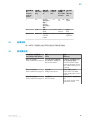
2 Correct use
The WL12G-3P3572S12 is an opto-electronic photoelectric retro-reflective sensor (re‐
ferred to as "sensor" in the following) for the optical, non-contact detection of objects,
animals, and persons. A reflector is required for this product to function. If the product
is used for any other purpose or modified in any way, any warranty claim against SICK
AG shall become void.
Photoelectric retro-reflective sensor
with additional option for the detection of transpa‐
rent objects.
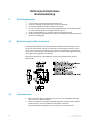
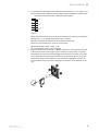
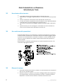
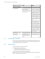
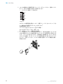
3 Commissioning
1 Check the distance between sensor and reflector. There is a max. sensing range of
500 mm with reflector P250F.
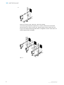
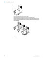
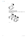
2 Mount the sensor and the reflector using suitable mounting brackets (see the SICK
range of accessories). Align the sensor and reflector with each other.
Note the sensor's maximum permissible tightening torque of Nm.
8016719.10DB| SICK
Subject to change without notice
1

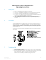
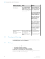
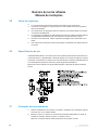
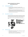
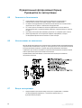
3 The sensors must be connected in a voltage-free state (V
S
= 0 V). The information
in the graphics [B] must be observed, depending on the type of connection:
–
Male connector connection: pin assignment
+ (L+)
Q
- (M)
brn
wht
blu
1
2
3
Q
blk
4
Teach
gra
5
Image: B
Only apply voltage / switch on the power supply (V
S
> 0 V) once all electrical con‐
nections have been completed. The green LED indicator lights up on the sensor.
Explanations of the connection diagram (graphic B):
Switching outputs Q and /Q (according to graphic B):
WL12G-3P3572S12 (PNP: load -> M)
ET = external teach-in (see Adjustment)
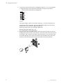
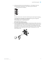
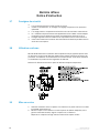
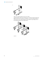
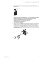
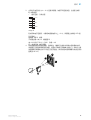
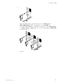
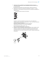
4 Align the sensor with a suitable reflector. Select the position so that the red emit‐
ted light beam hits the center of the reflector. The sensor must have a clear view of
the reflector, with no object in the path of the beam [see E]. You must ensure that
the optical openings of the sensor and reflector are completely clear. Place clear
off tape on clear foil at a distance of 60 mm between sensor and reflector.
3 COMMISSIONING
2
8016719.10DB| SICK
Subject to change without notice

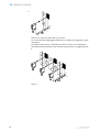
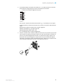
5
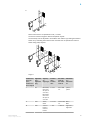
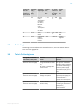
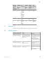
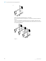
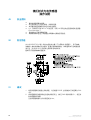
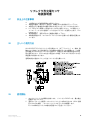
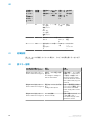
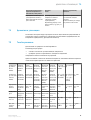
Sensor with teach-in via pushbutton and / or cable:
The sensor must be taught to detect transparent objects.
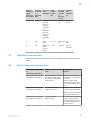
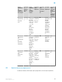
The sensitivity can be adjusted in accordance with Table J by pressing the teach-in
button or by activating the teach function via cable. Do not operate the teach-in
button using sharp objects.
Image: G
Teach-in mo‐
de for ob‐
jects /
Teach-in mo‐
de for objects
Light dam‐
ping /
Light dam‐
ping
Object ty‐
pe /
Object type
Teach-in
time /
Teach-in
time
Ext. Cable
teach-in /
Ext. Cable
teach-in
LED indica‐
tor /
LED indica‐
tor
I 6% PET bottle/
Clear tear
off tape on
clear foil /
PET bottle/
Clear tear
off tape on
clear foil
1 to 5 s 30 to 100
ms
yellow /
yellow
II 10% Glass /
Glass
5 to 10 s 100 to 200
ms
Blue /
Blue
III 18% Colored
bottles /
Colored
bottles
> 10 s > 200 ms Light blue /
Light blue
4
3
8016719.10DB| SICK
Subject to change without notice

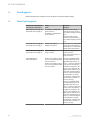
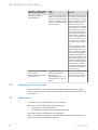
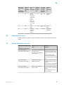
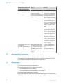
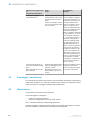
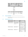
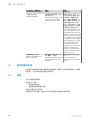
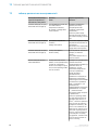
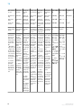
5 Fault diagnosis
Table indicates which measures are to be taken if the sensor stops working.
6 Table Fault diagnosis
LED indicator/fault pattern /
LED indicator/fault pattern
Cause /
Cause
Measures /
Measures
Green LED does not light up /
Green LED does not light up
No voltage or voltage below
the limit values /
No voltage or voltage below
the limit values
Check the power supply,
check all electrical connecti‐
ons (cables and plug connecti‐
ons) /
Check the power supply,
check all electrical connecti‐
ons (cables and plug connecti‐
ons)
Green LED does not light up /
Green LED does not light up
Voltage interruptions /
Voltage interruptions
Ensure there is a stable power
supply without interruptions /
Ensure there is a stable power
supply without interruptions
Green LED does not light up /
Green LED does not light up
Sensor is faulty /
Sensor is faulty
If the power supply is OK, re‐
place the sensor /
If the power supply is OK, re‐
place the sensor
Yellow LED flashes /
Yellow LED flashes
Sensor is still ready for opera‐
tion, but the operating conditi‐
ons are not ideal /
Sensor is still ready for opera‐
tion, but the operating conditi‐
ons are not ideal
Check the operating conditi‐
ons:
Fully align the beam of
light (light spot) with the re‐
flector. / Clean the optical sur‐
faces (sensor and reflector). /
Readjust the sensitivity / Re‐
flector is not suitable for the
application in question (we re‐
commend only using SICK re‐
flectors) / Check sensing ran‐
ge and adjust if necessary;
see graphic H. / Distance bet‐
ween the sensor and the re‐
flector is too long /
Check the operating conditi‐
ons: Fully align the beam of
light (light spot) with the re‐
flector. / Clean the optical sur‐
faces (sensor and reflector). /
Readjust the sensitivity / Re‐
flector is not suitable for the
application in question (we re‐
commend only using SICK re‐
flectors) / Check sensing ran‐
ge and adjust if necessary;
see graphic H. / Distance bet‐
ween the sensor and the re‐
flector is too long
5 FAULT DIAGNOSIS
4
8016719.10DB| SICK
Subject to change without notice

LED indicator/fault pattern /
LED indicator/fault pattern
Cause /
Cause
Measures /
Measures
Signal interruptions when ob‐
ject is detected /
Signal interruptions when ob‐
ject is detected
Depolarizing property of the
object surface (e.g., tape), re‐
flection /
Depolarizing property of the
object surface (e.g., tape), re‐
flection
Reduce sensitivity or change
the position of the sensor /
Reduce sensitivity or change
the position of the sensor
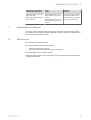
7 Disassembly and disposal
The sensor must be disposed of according to the applicable country-specific regulati‐
ons. Efforts should be made during the disposal process to recycle the constituent ma‐
terials (particularly precious metals).
8 Maintenance
SICK sensors are maintenance-free.
We recommend doing the following regularly:
•
Clean the external lens surfaces
•
Check the screw connections and plug-in connections
No modifications may be made to devices.
Subject to change without notice. Specified product properties and technical data are
not written guarantees.
DISASSEMBLY AND DISPOSAL 7
5
8016719.10DB| SICK
Subject to change without notice

Reflexions-Lichtschranke
Betriebsanleitung
9 Sicherheitshinweise
■
Vor der Inbetriebnahme die Betriebsanleitung lesen.
■
Anschluss, Montage und Einstellung nur durch Fachpersonal.
■
Kein Sicherheitsbauteil gemäß EU-Maschinenrichtlinie.
■
UL: Nur zur Verwendung in Anwendungen gemäß NFPA 79. Von UL gelistete Adap‐
ter mit Anschlusskabeln sind verfügbar. Enclosure type 1.
■
Gerät bei Inbetriebnahme vor Feuchte und Verunreinigung schützen.
■
Diese Betriebsanleitung enthält Informationen, die während des Lebenszyklus des
Sensors notwendig sind.
10 Bestimmungsgemäße Verwendung
Die WL12G-3P3572S12 ist eine optoelektronische Reflexions-Lichtschranke (im Fol‐
genden Sensor genannt) und wird zum optischen, berührungslosen Erfassen von Sa‐
chen, Tieren und Personen eingesetzt. Zur Funktion wird ein Reflektor benötigt. Bei je‐
der anderen Verwendung und bei Veränderungen am Produkt verfällt jeglicher Gewähr‐
leistungsanspruch gegenüber der SICK AG.
Reflexions-Lichtschranke mit Zusatzoption zur Erkennung transparenter Objekte
(WLxxG-xxxx).
11 Inbetriebnahme
1 Distanz zwischen Sensor und Reflektor prüfen. Der max. Schaltabstand beträgt
500 mm mit dem Reflektor P250F.
2 Sensor und Reflektor an geeignete Befestigungswinkel montieren (siehe SICK-Zu‐
behör-Programm). Sensor und Reflektor zueinander ausrichten.
Maximal zulässiges Anzugsdrehmoment des Sensors von Nm beachten.
6
8016719.10DB| SICK
Subject to change without notice

3 Anschluss der Sensoren muss spannungsfrei (V
S
= 0 V) erfolgen. Je nach An‐
schlussart sind die Informationen in den Grafiken [vgl. B] zu beachten:
–
Steckeranschluss: Pinbelegung
+ (L+)
Q
- (M)
brn
wht
blu
1
2
3
Q
blk
4
Teach
gra
5
Abb.: B
Erst nach Anschluss aller elektrischen Verbindungen die Spannungsversorgung (V
S
> 0 V) anlegen bzw. einschalten. Am Sensor leuchtet die grüne Anzeige-LED.
Erläuterungen zum Anschlussschema (Grafik B):
Schaltausgänge Q bzw. /Q (gemäß Grafik B):
WL12G-3P3572S12 (PNP: Last -> M)
ET = externer Teach (siehe Einstellung)
4 Sensor auf geeigneten Reflektor ausrichten. Positionierung so wählen, dass der ro‐
te Sendelichtstrahl in der Mitte des Reflektors auftrifft. Der Sensor muss freie Sicht
auf den Reflektor haben, es darf sich kein Objekt im Strahlengang befinden [vgl.
E]. Es ist darauf zu achten, dass die optischen Öffnungen von Sensor und Reflektor
vollständig frei sind. Transparente Folie mit Faden im Abstand 60 mm in den
Strahlengang bringen.
INBETRIEBNAHME 11
7
8016719.10DB| SICK
Subject to change without notice

5
Sensor mit Teach-in über Taste und / oder über Leitung:
Zur Erkennung transparenter Objekte ist ein Teachen des Sensors erforderlich.
Durch Drücken der Teach-in-Taste bzw. Aktivierung der Teach-Funktion über Lei‐
tung wird die Empfindlichkeit gemäß Tabelle J eingestellt. Teach-in-Taste nicht mit
spitzen Gegenständen betätigen.
Abb.: G
11 INBETRIEBNAHME
8
8016719.10DB| SICK
Subject to change without notice

Teach-in-Mo‐
dus für Ob‐
jekte /
Teach-in mo‐
de for objects
Lichtdämp‐
fung /
Light dam‐
ping
Objekttyp /
Object type
Teach-in-
Zeit /
Teach-in
time
Ext. Teach-
in über Lei‐
tung /
Ext. Cable
teach-in
Anzeige-
LED /
LED indica‐
tor
I 6 % PET-Fla‐
sche /
Transparen‐
ter Faden
mit Folie /
PET-Fla‐
sche /
Transparen‐
ter Faden
mit Folie
1 ... 5 s 30 ... 100
ms
gelb /
yellow
II 10 % Glas /
Glass
5 ... 10 s 100 ... 200
ms
blau /
Blue
III 18 % Farbige Fla‐
schen /
Colored
bottles
> 10 s > 200 ms hellblau /
Light blue
13 Fehlerdiagnose
Tabelle zeigt, welche Maßnahmen durchzuführen sind, wenn die Funktion des Sen‐
sors nicht mehr gegeben ist.
14 Tabelle Fehlerdiagnose
Anzeige-LED / Fehlerbild /
LED indicator/fault pattern
Ursache /
Cause
Maßnahme /
Measures
grüne LED leuchtet nicht /
Green LED does not light up
keine Spannung oder Span‐
nung unterhalb der Grenzwer‐
te /
No voltage or voltage below
the limit values
Spannungsversorgung prüfen,
den gesamten elektrischen
Anschluss prüfen (Leitungen
und Steckerverbindungen) /
Check the power supply,
check all electrical connecti‐
ons (cables and plug connecti‐
ons)
grüne LED leuchtet nicht /
Green LED does not light up
Spannungsunterbrechungen /
Voltage interruptions
Sicherstellen einer stabilen
Spannungsversorgung ohne
Unterbrechungen /
Ensure there is a stable power
supply without interruptions
grüne LED leuchtet nicht /
Green LED does not light up
Sensor ist defekt /
Sensor is faulty
Wenn Spannungsversorgung
in Ordnung ist, dann Sensor
austauschen /
If the power supply is OK, re‐
place the sensor
12
9
8016719.10DB| SICK
Subject to change without notice

Anzeige-LED / Fehlerbild /
LED indicator/fault pattern
Ursache /
Cause
Maßnahme /
Measures
gelbe LED blinkt /
Yellow LED flashes
Sensor ist noch betriebsbe‐
reit, aber die Betriebsbedin‐
gungen sind nicht optimal /
Sensor is still ready for opera‐
tion, but the operating conditi‐
ons are not ideal
Betriebsbedingungen prüfen:
Lichtstrahl (Lichtfleck) voll‐
ständig auf den Reflektor aus‐
richten / Reinigung der opti‐
schen Flächen(Sensor und
Reflektor)
/ Empfindlichkeit
neu einstellen / Reflektor eig‐
net sich nicht für gewählte Ap‐
plikation (wir empfehlen, aus‐
schließlich SICK-Reflektoren
zu verwenden) / Schaltab‐
stand überprüfen und ggf. an‐
passen, siehe Grafik H. / Ab‐
stand zwischen Sensor und
Reflektor ist zu groß /
Check the operating conditi‐
ons: Fully align the beam of
light (light spot) with the re‐
flector. / Clean the optical sur‐
faces (sensor and reflector). /
Readjust the sensitivity / Re‐
flector is not suitable for the
application in question (we re‐
commend only using SICK re‐
flectors) / Check sensing ran‐
ge and adjust if necessary;
see graphic H. / Distance bet‐
ween the sensor and the re‐
flector is too long
Signalunterbrechungen bei Ob‐
jektdetektion /
Signal interruptions when ob‐
ject is detected
Depolarisierende Eigenschaft
der Objektoberfläche (z. B. Fo‐
lie), Umspiegelung /
Depolarizing property of the
object surface (e.g., tape), re‐
flection
Empfindlichkeit reduzieren
oder Sensorposition verän‐
dern /
Reduce sensitivity or change
the position of the sensor
15 Demontage und Entsorgung
Die Entsorgung des Sensors hat gemäß den länderspezifisch anwendbaren Vorschrif‐
ten zu erfolgen. Für die enthaltenen Wertstoffe (insbesondere Edelmetalle) ist im Rah‐
men der Entsorgung eine Verwertung anzustreben.
16 Wartung
SICK-Sensoren sind wartungsfrei.
Wir empfehlen, in regelmäßigen Abständen
•
die optischen Grenzflächen zu reinigen
•
Verschraubungen und Steckverbindungen zu überprüfen
Veränderungen an Geräten dürfen nicht vorgenommen werden.
Irrtümer und Änderungen vorbehalten. Angegebene Produkteigenschaften und techni‐
sche Daten stellen keine Garantieerklärung dar.
15 DEMONTAGE UND ENTSORGUNG
10
8016719.10DB| SICK
Subject to change without notice

Barrière réflexe
Notice d'instruction
17 Consignes de sécurité
■
Lire la notice d'instruction avant la mise en service.
■
Confier le raccordement, le montage et le réglage uniquement à un personnel
spécialisé.
■
Il ne s'agit pas d'un composant de sécurité au sens de la directive machines CE.
■
UL : utilisation uniquement dans des applications selon la NFPA 79. Des adapta‐
teurs listés UL avec câbles de connexion sont disponibles. Enclosure type 1.
■
Protéger l'appareil contre l'humidité et les impuretés lors de la mise en service.
■
Cette notice d'instruction contient des informations nécessaires pendant toute la
durée de vie du capteur.
18 Utilisation conforme
WL12G-3P3572S12 est une barrière réflexe optoélectronique (appelée capteur dans
ce document) qui permet la détection optique sans contact d'objets, d'animaux et de
personnes. Un réflecteur est nécessaire à son fonctionnement. Toute autre utilisation
ou modification du produit annule la garantie de SICK AG.
Détecteur à réflexion directe avec option de détection d'objets transparents.
19 Mise en service
1 Contrôler la distance entre le capteur et le réflecteur. La portée max. avec le réflec‐
teur P250F est de 500 mm.
2 Monter le capteur et le réflecteur sur des équerres de fixation adaptées (voir la
gamme d'accessoires SICK). Aligner le capteur sur le réflecteur.
Respecter le couple de serrage maximum autorisé du capteur de Nm
12
8016719.10DB| SICK
Subject to change without notice

3 Le raccordement des capteurs doit s'effectuer hors tension (V
S
= 0 V). Selon le mo‐
de de raccordement, respecter les informations contenues dans les schémas [B] :
–
Raccordement du connecteur : affectation des broches
+ (L+)
Q
- (M)
brn
wht
blu
1
2
3
Q
blk
4
Teach
gra
5
Image: B
Après avoir terminé tous les raccordements électriques, enclencher l'alimentation
électrique (V
S
> 0 V). La DEL verte s'allume sur le capteur.
Explications relatives au schéma de raccordement (schéma B) :
Sorties de commutation Q ou /Q (selon le schéma B) :
WL12G-3P3572S12 (PNP : charge -> M)
ET = apprentissage externe (voir le réglage)
4 Aligner le capteur sur un réflecteur adéquat. Sélectionner la position de sorte que
le faisceau lumineux émis rouge touche le réflecteur en plein milieu. Le capteur
doit disposer d'un champ de vision dégagé sur le réflecteur, il ne doit donc y avoir
aucun objet dans la trajectoire du faisceau [voir E]. S'assurer que les ouvertures
optiques du capteur et du réflecteur sont parfaitement dégagées. Introduire un
film transparent avec un fil dans la trajectoire du faisceau, à une distance de 60
mm.
MISE EN SERVICE 19
13
8016719.10DB| SICK
Subject to change without notice

5
Capteur avec apprentissage via touche et/ou câble :
L'apprentissage du capteur est nécessaire pour la détection d'objets transparents.
Régler la portée selon le tableau J en appuyant sur la touche d'apprentissage ou
en activant la fonction apprentissage via l'entrée dédiée. Ne pas appuyer sur la
touche apprentissage avec des objets pointus.
Image: G
19 MISE EN SERVICE
14
8016719.10DB| SICK
Subject to change without notice

Mode d'ap‐
prentissage
pour les ob‐
jets /
Teach-in mo‐
de for objects
Atténuation
de la lumiè‐
re /
Light dam‐
ping
Type d'ob‐
jet /
Object type
Durée d'ap‐
prentissa‐
ge /
Teach-in
time
Apprentis‐
sage ext.
par câble /
Ext. Cable
teach-in
LED d'é‐
tat /
LED indica‐
tor
I 6 % Bouteille en
plastique /
fil transpa‐
rent avec
film /
Bouteille en
plastique /
fil transpa‐
rent avec
film
1 à 5 s 30 à 100
ms
jaune /
yellow
II 10 % Verre /
Glass
5 à 10 s 100 à 200
ms
bleu /
Blue
III 18 % Bouteilles
de cou‐
leur /
Colored
bottles
> 10 s > 200 ms bleu clair /
Light blue
21 Diagnostic
Le tableau présente les mesures à appliquer si le capteur ne fonctionne plus.
22 Tableau Diagnostic
LED d'état / image du défaut /
LED indicator/fault pattern
Cause /
Cause
/
Measures
La LED verte ne s'allume pas /
Green LED does not light up
Pas de tension ou tension in‐
férieure aux valeurs limites /
No voltage or voltage below
the limit values
Contrôler l'alimentation élect‐
rique, contrôler tous les bran‐
chements électriques (câbles
et connexions) /
Check the power supply,
check all electrical connecti‐
ons (cables and plug connecti‐
ons)
La LED verte ne s'allume pas /
Green LED does not light up
Coupures d'alimentation élect‐
rique /
Voltage interruptions
S'assurer que l'alimentation
électrique est stable et ini‐
nterrompue /
Ensure there is a stable power
supply without interruptions
La LED verte ne s'allume pas /
Green LED does not light up
Le capteur est défectueux /
Sensor is faulty
Si l'alimentation électrique est
en bon état, remplacer le cap‐
teur /
If the power supply is OK, re‐
place the sensor
20
15
8016719.10DB| SICK
Subject to change without notice

LED d'état / image du défaut /
LED indicator/fault pattern
Cause /
Cause
/
Measures
La LED jaune clignote /
Yellow LED flashes
Le capteur est encore opérati‐
onnel, mais les conditions d'u‐
tilisation ne sont pas idéales /
Sensor is still ready for opera‐
tion, but the operating conditi‐
ons are not ideal
Vérifier les conditions d'utilisa‐
tion : Diriger le faisceau lumi‐
neux (spot lumineux) entière‐
ment sur le réflecteur / Netto‐
yage des surfaces optiqu‐
es
(capteur et réflecteur) /
Régler à nouveau la sensibili‐
té / Le réflecteur ne convient
pas à l'application sélection‐
née (nous recommandons d'u‐
tiliser exclusivement des ré‐
flecteurs SICK) / Contrôler la
portée et éventuellement l'a‐
dapter, voir le schéma et H. /
La distance entre le capteur
et le réflecteur est trop gran‐
de /
Check the operating conditi‐
ons: Fully align the beam of
light (light spot) with the re‐
flector. / Clean the optical sur‐
faces (sensor and reflector). /
Readjust the sensitivity / Re‐
flector is not suitable for the
application in question (we re‐
commend only using SICK re‐
flectors) / Check sensing ran‐
ge and adjust if necessary;
see graphic H. / Distance bet‐
ween the sensor and the re‐
flector is too long
Coupures de signal lors de dé‐
tection d'objet /
Signal interruptions when ob‐
ject is detected
Propriété dépolarisante de la
surface de l'objet (par ex.
film), réflexions /
Depolarizing property of the
object surface (e.g., tape), re‐
flection
Réduire la sensibilité ou chan‐
ger la position du capteur /
Reduce sensitivity or change
the position of the sensor
23 Démontage et mise au rebut
La mise au rebut du capteur doit respecter la réglementation nationale en vigueur.
Dans le cadre de la mise au rebut, veiller à recycler les matériaux (notamment les mé‐
taux précieux).
24 Maintenance
Les capteurs SICK ne nécessitent aucune maintenance.
Nous vous recommandons de procéder régulièrement
•
au nettoyage des surfaces optiques
•
au contrôle des vissages et des connexions enfichables
Ne procéder à aucune modification sur les appareils.
Sujet à modification sans préavis. Les caractéristiques du produit et techniques four‐
nies ne sont pas une déclaration de garantie.
23 DÉMONTAGE ET MISE AU REBUT
16
8016719.10DB| SICK
Subject to change without notice

Barreira de luz de reflexão
Manual de instruções
25 Notas de segurança
■
Ler as instruções de operação antes da colocação em funcionamento.
■
A conexão, a montagem e o ajuste devem ser executados somente por pessoal
técnico qualificado.
■
Os componentes de segurança não se encontram em conformidade com a Direti‐
va Europeia de Máquinas.
■
UL: Somente na utilização em aplicações de acordo com NFPA 79. Estão disponív‐
eis adaptadores listados pela UL com cabos de conexão. Enclosure type 1.
■
Durante o funcionamento, manter o aparelho protegido contra impurezas e um‐
idade.
■
Este manual de instruções contém informações necessárias para toda a vida útil
do sensor.
26 Especificações de uso
O WL12G-3P3572S12 é uma barreira de luz de reflexão optoeletrônica (doravante de‐
nominada "sensor") utilizada para a detecção óptica, sem contato, de objetos, animais
e pessoas. É necessário um refletor para o funcionamento. Qualquer utilização diferen‐
te ou alterações do produto provocam a perda da garantia da SICK AG.
Barreira de luz de reflexão com opção adicional para a detecção de objetos transpa‐
rentes.
27 Colocação em funcionamento
1 Verificar a distância entre o sensor e o refletor. A distância de comutação máxima
é de 500 mm com o refletor P250F.
2 Montar o sensor e o refletor em cantoneiras de fixação adequadas (ver linha de
acessórios da SICK). Alinhar o sensor e o refletor entre si.
Observar o torque de aperto máximo permitido de Nm para o sensor.
18
8016719.10DB| SICK
Subject to change without notice

3 A conexão dos sensores deve ser realizada em estado desenergizado (V
S
= 0 V).
Conforme o tipo de conexão, devem ser observadas as informações contidas nos
gráficos [cp. B]:
–
Conector: Pin-out
+ (L+)
Q
- (M)
brn
wht
blu
1
2
3
Q
blk
4
Teach
gra
5
Image: B
Instalar ou ligar a alimentação de tensão (V
S
> 0 V) somente após a conclusão de
todas as conexões elétricas. O indicador LED verde está aceso no sensor.
Explicações relativas ao esquema de conexões (Gráfico B):
Saídas de comutação Q ou /Q (conforme o gráfico B):
WL12G-3P3572S12 (PNP: carga -> M)
TE = Teach externo (ver Ajuste)
4 Alinhar o sensor ao refletor adequado. Posicionar, de forma que o feixe da luz de
emissão vermelha incida sobre o centro do refletor. O espaço entre o sensor e o
refletor deve estar desimpedido; não pode haver objetos no caminho óptico [cp.
E]. Certificar-se de que as aberturas ópticas do sensor e do refletor estejam com‐
pletamente livres. Colocar a película transparente com fio no caminho óptico com
uma distância de 60 mm.
COLOCAÇÃO EM FUNCIONAMENTO 27
19
8016719.10DB| SICK
Subject to change without notice

5
Sensor com Teach-in através da tecla e / ou do cabo:
Para a detecção de objetos transparentes, é necessário um processo de teach do
sensor.
O ajuste da sensibilidade é efetuado de acordo com a tabela J apertando a tecla
Teach-in ou ativando a função Teach através do cabo. Não acionar a tecla Teach-in
com objetos pontiagudos.
Image: G
27 COLOCAÇÃO EM FUNCIONAMENTO
20
8016719.10DB| SICK
Subject to change without notice

Modo Teach-
in para obje‐
tos /
Teach-in mo‐
de for objects
Atenuação
de luz /
Light dam‐
ping
Tipo de ob‐
jeto /
Object type
Tempo de
Teach-in /
Teach-in
time
Ext. Teach-
in através
de cabo /
Ext. Cable
teach-in
Indicador
LED /
LED indica‐
tor
I 6 % Garrafa
PET / fio
transparen‐
te com pelí‐
cula /
Garrafa
PET / fio
transparen‐
te com pelí‐
cula
1 ... 5 s 30 ... 100
ms
Amarelo /
yellow
II 10% Vidro /
Glass
5 ... 10 s 100 ... 200
ms
azul /
Blue
III 18 % Garrafas
coloridas /
Colored
bottles
> 10 s > 200 ms azul claro /
Light blue
29 Diagnóstico de erros
A tabela mostra as medidas a serem executadas, quando o sensor não estiver funcio‐
nando.
30 Tabela Diagnóstico de erros
Indicador LED / padrão de er‐
ro /
LED indicator/fault pattern
Causa /
Cause
Medida /
Measures
LED verde apagado /
Green LED does not light up
Sem tensão ou tensão abaixo
dos valores-limite /
No voltage or voltage below
the limit values
Verificar a alimentação de
tensão, verificar toda a cone‐
xão elétrica (cabos e conecto‐
res) /
Check the power supply,
check all electrical connecti‐
ons (cables and plug connecti‐
ons)
LED verde apagado /
Green LED does not light up
Interrupções de tensão /
Voltage interruptions
Assegurar uma alimentação
de tensão estável sem inter‐
rupções /
Ensure there is a stable power
supply without interruptions
LED verde apagado /
Green LED does not light up
Sensor está com defeito /
Sensor is faulty
Se a alimentação de tensão
estiver em ordem, substituir o
sensor /
If the power supply is OK, re‐
place the sensor
28
21
8016719.10DB| SICK
Subject to change without notice
La pagina si sta caricando...
La pagina si sta caricando...
La pagina si sta caricando...
La pagina si sta caricando...
La pagina si sta caricando...
La pagina si sta caricando...
La pagina si sta caricando...
La pagina si sta caricando...
La pagina si sta caricando...
La pagina si sta caricando...
La pagina si sta caricando...
La pagina si sta caricando...
La pagina si sta caricando...
La pagina si sta caricando...
La pagina si sta caricando...
La pagina si sta caricando...
La pagina si sta caricando...
La pagina si sta caricando...
La pagina si sta caricando...
La pagina si sta caricando...
La pagina si sta caricando...
La pagina si sta caricando...
La pagina si sta caricando...
La pagina si sta caricando...
La pagina si sta caricando...
La pagina si sta caricando...
La pagina si sta caricando...
La pagina si sta caricando...
-
 1
1
-
 2
2
-
 3
3
-
 4
4
-
 5
5
-
 6
6
-
 7
7
-
 8
8
-
 9
9
-
 10
10
-
 11
11
-
 12
12
-
 13
13
-
 14
14
-
 15
15
-
 16
16
-
 17
17
-
 18
18
-
 19
19
-
 20
20
-
 21
21
-
 22
22
-
 23
23
-
 24
24
-
 25
25
-
 26
26
-
 27
27
-
 28
28
-
 29
29
-
 30
30
-
 31
31
-
 32
32
-
 33
33
-
 34
34
-
 35
35
-
 36
36
-
 37
37
-
 38
38
-
 39
39
-
 40
40
-
 41
41
-
 42
42
-
 43
43
-
 44
44
-
 45
45
-
 46
46
-
 47
47
-
 48
48


SICK WL12G-3P3572S12 Istruzioni per l'uso
- Tipo
- Istruzioni per l'uso
- Questo manuale è adatto anche per
in altre lingue
Documenti correlati
-
SICK WL23-2 Compact photoelectric sensor Istruzioni per l'uso
-
-
-
-
-
-
-
-
-