TANDBERG TCD 340A Alignment Instructions
- Tipo
- Alignment Instructions

TANDBERG
^
TCD
34OA-
Circuit
DagraTs
wrth
A
li
gnrn
en
tTn
st
r
u
cti
o
n
s
Mechanical
adjustments,
see
Service
Manual
for
TCD
330,
Ordering
No.
714021

Electrical
adjustments
for
the
TCD
3404
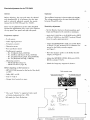
General
Before
adjusting,
the
tape path must be cleaned
and demagnetized. It is
necessary
that the tape
path is
correctly adjusted, consult the service
manual
for
the
TCD
330, part
No.
714021.
Carry
out
the
adjustments
in the
order described
because the adjustments
affect
each other.
Remove
the top
panel, base
panel,
and
right side
panel.
Equipment
required
-
2
volt
meters
-
Audio
signal
generator
-
Frequency
counter
-
Distortion meter
-
Wow
and
flutter
meter
-
Tandberg
test cassettes
-
No.
21
(Speed check, 1000 Hz)
- No.
22
(Wow
and
flutter
check, 3150 Hz)
-
No.
23
(Azimuth
adj. playb. head, 6300 Hz)
-
No.
24
(Playback
level
adj., 1000 Hz)
-
Measuring cassettes
-
Maxell
UD
XL
I (Type I)
-
Maxell
UD
XL
Il
(Type
II)
Before adjusting,
set
the
buttons
to:
-
MPX-FILTER (situated
at the back of the deck)
to
OFF.
-
Dolby
NR*
to Off.
-
Tape to
Type
I.
-
Output Level
controls to
max.
*
The word
"Dolby" is registered trade marh
of Dolby
Laboratories
Inc.,
USA.
NR stands
for
l'{oise Reduction.
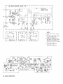
Oscillator
The
oscillator
frequency
is
between
80 and
100
kHz.
The
voltage
measured on the erase
head should
be
between
25
and 32 volts.
Sensitivity
adiustment
- Set
the Monitor
button to Source position,
and
Input and Output Level
controls
to
maximum.
-
Apply
8mV,1000
Hz
to the
RADIO socket
(DIN)
or
80
mV,l000
Hz to the INPUT sockets
(Phono)
from
the audio signal
generator.
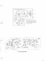
-
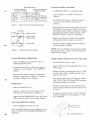
Adjust the
SENSITIVITY ADJ. pots. Rl01-R201
to
obtain 77 5 mY measured on
a
voltme
ter
con-
nected
to the
Dolby
encoder output,
see
Figure
1.
-
Move
the
measure
probe
to the
Dolby decoder
output,
see
Figure
2.
- Adjust
the
SOURCE
LEVEL ADJ. pots.
Rl18-
R218
to obtain 7 7 5
mV
.
-
Check the
frequency response in
Source.
Dolby
encoder output
Right channel meas.point
Left channel
meas.point
_
|
RroBP
I
Prosr.
.:.,
P)lI P
I RTL LLvtL
T'Pf
I TAPI
REc METER
J-
- - -l
R2rg
R
RrrB
L
R2oq Ra
agrog
!
aori*aa a?ura
REc LEV€L aoJ TYPE
tl TAPE
TRIMMING
POIS
ON
MAIN AOARD SE€N FAOM SOLOER
SIDE
Figure
1 Trimming
pots.
and Dolby
encoder rneasurement
points

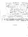
Figure
2 Dolby
decoder measurern,ent points
Playback, azimuth
Playback, height
Record,
azimuth
Record, height
Figure
3 Adjustments
for
the heads
Azimuth adjustment,
playback
head
-
Insert
a
Tandberg
test cassette
No.
23
or a
standard azimuth
cassette.
- Set the
Monitor button
to
Tape
and connect a
voltmeter to
each
channel of
the OUTPUT
sockets.
-
Press
the
Play
button.
Adjust the playback
azimuth screws
shown in
Figure
3
to
obtain
maximum reading on each channel.
Playback
level
- Insert
test cassette
No.
24.
-
Connect
a voltmeter to
each
channel
of
the
Dolby
decoder output
shown
in Figure
2.
- Adjust the PLAYBACK LEVEL pots.
Rl19
and
R219
until
you
read 775 mV
on
each
channel.
Level meter adjustment,
playback
-
Insert Tandberg test cassette No.
24.
When the playback
level is
correct, adjust the
level
meter to 0
dB with
PLAYBACK
METER Rl14
and R214.
Azimuth
and
height,
record head
-
Use Maxell UD XL
I
or an
equivalent
tape.
-
Applf'
1000
Hz
to
the INPUT
sockcts
both
channels.
-
Set the
Monitor
button to Tape and connect
a
voltmeter to the OUTPUT sockets both
channels.
-
Press
the
Record
button
and
turn the two record
head height
screws shown
in
Figure
3 by equal
amounts
(the
same number of
degrees) to obtain
the maximum reading
on
both
channels
of the
OUTPUT
sockets, or
the best compromise.
-
Adjust the azimuth (10
kHz)
and the
height
alternatively,
until the head sits correctly.
-
Azimuth
can also be adjusted
with
the
built-in
control oscillator
(10 kHz).
NOTE! The
record height screws
must be adjusted
by
equal amounts
to
ensure
that the
head paral-
lelism does
not change.
Overall
frequency response with Type
I Tape
(bias)
-
Set the
Monitor button to
Tape.
- Apply
1000 Hz
from
the
signal generator to one
of the
inputs.
- Re duce the
level at the signal
generator by 35 dB
or reduce
the
level
by a similar
amount on the
Input Level controls.
- Press
the
Record button, and adjust
the BIAS
ADJ. TYPE
I
TAPE, C1502 and Cl602 to
obtain
maximum reading at the
outputs.
- Sweep the audio
generator
throush the
full fre-
quency
range
and check
that
the
response
curve
is correct.
- If necessary,
adjust
the curve with C1502 and
C1602
to
obtain
the correct
response,
t
3
dB,
30 to 18000
Hz.
-'.\
Dolby decoder outpul
Left channel
meas,
point
Or measure
on 81303
Right
channel meas.
point
Or measure on
R1403
i^
..
^O
o^v^
^Va
.J n.':
\
-v/-
o<-o
^
Bias adjustments

Adjusting
the record
current
(Source/Tape)
Distortion
Type
I Tape
Record 1000
Hz
at
0
dB
deflection on
the meters.
I
- Use
the
same input
level as
for
the
bias adjust-
The max. distortion for
record/playback
is 3%.
ment
(- 35 dB)
and
1000 Hz.
- Adjust
the record current
by
means
of
the
Erase
test
REC. LEVEL
ADJ. pots. Rl08
and
R208
to
obtain the
same output
level
for both
positions
Connect a microphone
to the TCD 3404 and
\
on
the
Monitor
butron.
record an
overload signal. Record again
to
erase
the
overload
recording
and play
back to
ensure
that
-
Then depress
the Dolby
NR
button and check
the overload signal cannot be
heard.
c
the
overall
frequency response.
Az
imuth
meter
adjustment
Overall
frequency response
with Type ll Tape
(bias)
-
Set
the
built-in
oscillator
to
ON.
-
Use
the
same
procedure as
for
the
Type I
tape.
-
Set the Output
Level
controls
to
maximum.
-
Insert
a
Maxell UD
XL
II or an
cquivalent tape.
- Insert
aType I tape and
press
the
Record
button.
- Set the
Tape button
to
Type
II
position,
and
/
press
the
Record
button.
-
Adjust
p.Z2Z
(AZIMUTH METER
ADJ.)
to
-
check
the frequency response, and if
necessary,
ff.or:"r:t-"tely
-
3
dB deflection on the right
adjust the
BIAS ADJ. TYPE II TAPE, pot.
Rl
508
to obtain the correct
response.
_
Check also that the meter
deflection
with a
Type II
tape is
within
the meter
scale.
Adjusting the
record current
(Source/Tape)
Type ll Tape
Speed
check
- Use the
same input
level
as for the bias adjust-
ment
(-
35
dB)
and
1000IIz.
Play
back Tandberg
test
cassette
No.
21
(speed
check
1000 Hz)
and measure with
a
frequency
-
Adjust the record current by means of
the
REC.
counter
on the
OUTPUT sockets:
LEVEL ADJ. pots
Rl09
and
R209
to
obtain
the
<!
03%
(995
to
1005 Hz).
same output
level
for
both positions on
the
Monitor
button.
Wow
and flutter
R1101 and
R1201 affect the treble
response
in
I
the
frequency region 15-18 kHz on the playback
Play
back a Tandberg test cassette No.
22
curve forall types of
tapes.
(3150
Hz)
and
measure with
a wow
and
flutter
meter
on the OUTPUT sockets:
Level
meters
adjustment,
record
weighted RMS:
(
0.09%
Weighted Peak
DIN 45511 10.2%
-
Set the Monitor button to Tape'
Record/prayback
-
Apply
1000 Hz
to
the INPUT
sockets
(both
Record
from a generator 31b0 Hz
(check
with
a
channels)'
frequency
.or,ni., and measure
with the wow
and
flutter
meter on the OUTPUT sockets.
-
Press
the
Record button and adjust the
Input
Level
controls
for 1.5 volt ,.uiing on
thi
weighted RMS:
(
0'12%
OL-rTPI-IT
sockets.
- Adjust the
REC. METER pots.
Rl13 and
R213
to
obtain
0 dB
on
the level meters.
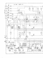
g
Al

,
!^
^
r--
-----l
;
A4 EOUAL
REC
AMP
(NOTES
I-4)
I
alaL
:5588
lo!
0705
BC 5488
L-
PART
A1
=
Lla
c.
I
r_=;l
l{
----J
\\
|
.-:=l
fr;--'l
Lu"Les.
ctarnwsrspEsrFrE!,REssrANcErNoHMs
: :^t !i 1
I
eLur, rERM NAL
|o's
FoR TsE R C8ANNEL aRE
c
vEN N
"cr
_tl-+:r-,
I
BplchFls
EEsloE IHE
L CHANNEL
PLlo llRM
NrL ills
.la
rero
Ll,'
|
3.,-,rr*ur.
ia5
r0r,rse. aND R cnANlrL Hssor
d99as
-
!
IAPE
.r
l:
I
ctMp!.!F!T !o s WHEN RFFER|N6 ID R CFANNEL coMpoNEtt
I
I
ADD
tL)
Tt TfE L CiANNEL
ND5
IEG n70r 0F THr
]
I
L CH3KNIL
dA5
lHE
SAME VALUE 45 RSOI
CF
TNE R CH
PART
OF
i
|
4.
cs,o ;zn
JN EURoIEAN MooELs
o r---{FFi7l-<
.---.1R Anqf<
-qdUU
-+
a
.--1&.]-zj-
EFI
'--L5.9.]LI-
Fmsl ?
l*
|
3.*u
{oeot
*-{Es2n]-.
,--rurrl--.
I'
-Iceoi
-.{F:dgi}-
oeosp
L8;)a
$a I
a
-
-
.t{l= .ttl
=^-.-
/ Ic804
F{F807F{
O80sk
a
-E
?
o--{n6btrL+
"o9
-
=
^.()
elneosl<
.-@-
--@-
ru.-gg1f-
e
----E;;r1-
M
-
>_lnTril_+
--@;""9
._@-.
g
*Fn3]-
Ldu/T
*ffi-. fce,z
u
",r,
l
r
*m-
,.,oisl illilt
rHl-1
t-lR8olF{
|
A2 5oro
o\LlvDtt
I
_ll
*q-m1-.
T,
-@-.^-^,1
j'ou
.+ iF
--m;-^!"f
T
diTii@_-
+__lnn
r......._l<
.c.t1t .C71z B
I t\
.---1F rrr- + +
'1x'
--lalool--.
*@*-
--i#-
*@-
&'-@-
J,,-_{Rf19}--
Tc70.r
e{nrtdr-
=
--EjlI-
a
olaL)ry
,qo7o5 ,,c7oe ]fl!-
r@-
r
{ €
*iF"" *E}-
g
t.,.
l-r
z :-l
P
1't
G-F@{
TcTos
li..l I
6 3
I .+
rfttatafl
J4o
iiiiit+ti
*€zG-
.-'-_'
I
J
tE?
l
I
I
I
! l
r--,:
oF
l:li
;
i
lJill'
crorl{ffif
fA F""l I
EIE[:li]
|
Fldl
"T
T
],,.I-
^
A4
EOUAL
REC.AMP.

wTs
--
--S*--Et*
+ #u.*
I
*l
I"E l*
.
e<
lP-
-fl,hj,
t
,h!,
i t lil T Flt
,E,E'--w
.----.----
F- JlT.tT
G.
ll
'"
-'--I
nrprnr r *,n*;
"9it
la"a
-
-
TI
I
,t
"+ffHs{
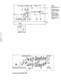
A1 MAIN
BOARD
A
^

a
A
rgr
I
J
ta
I
H
I
EI
T
I
t
I
Itl
T
t
IEI
T
r
I
I
I
{
.K)
F
4
-
.Lsr .g^.. r*l
l# ?
3l_
_:ElilrEI
g3+;Fts
I
ilBffiJE&ASHSI
;@oo
9FaO-
L@J
P20 il
I
:l
-11.r
I
r
I
I
I
I
I
I
I
I
I
I
I
I
I
I
I
I
I
I
I
I
I
I
I
I
I
I
I
I
I
I
I
I
I
I
I
I
I
I
I
I
I
I
I
L
A1
MAIN BOAF
t-------1
-;.i;lr
t-tr
tt_J
ll
ll;
E!t
F--tr--+''r
*?
8*
*l
ao
\/W{
WT?
tEl
-r
--ol
|:I I T
T.
I
l-
-uFn:ii.-l
l-
'HE
SWITCHES ARE SEEN FROM THE
SOLDER SID€
OOLAY NR,
oowFa
5i;
;
No f -aFE MeMoRy voNr.oR
qFc
ON
J
FM
PREII
I
r
cl tP
qI
IP
qI
IP
^

N BOARD
(
NOTES 1-1
)
,2, e_lioT--fi
l-re*-^"-"Ei.
-'l
|
".,"
:qs I
I
L€VEL ADJ
;ii
I
:tJ rlr
i
-'l
C
t:
^^_c,;-----]
.-5lTl
Foua, P-aYB.
I
\-l | |
t
auP l-cH
P2trl
I
'--Tll
LIE'-'?
'"-'
^' '"
-:
r€c.
.EVEI
u
-
"l-",1:l---t
"
ITT
1:l
lil;r1,1
i-v".:. iI
Pr8:
l16j
JL6.
l------l
l
s6a
I
I
|
.rn
I
L"".ltt"SJ
o I03
actaTa
rl
ruo I
13L
(lP'*,
lrl
l-]ru.q---i't
L-_ J
IEVEL AO]
r
I
I
REC
LIVET AD]
tl
L-----J
l-"90..!i
REC.
METER
",'u
[[-T*J
- - - - -l
REC. METER
'''
:l- T-
-
-
-
- - -1
nrrs St
t
plo
r
THE
FM-MPX AND AZIMUTH CAL.
SWITCHES
ARE
STEN
FROM THE FRONI SIDE.
^l_
BL_:_=l Blororl
tzx 123456
FH MPX
SWLICH AZIV!TH
CAL. SWITCA,
P:ACED ON
A1.
PLAC€O ON 43.
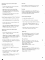
NOTES:
l.
unrEss orrenwtse
spEcFrEo, REsTsTANcE N oHMs.
2.
oaL s*'raras aRE sHowN rN
TrE
-powER
oFF
posrtoN.
3.
Lea,
a"n"uea coMpoNENTs aavE
ror-r30, RroHr CHANNEL
coMPoNENTS HAV€ 201-230.
COMPONENTS COMMON FOR EOTH
CHANNELS HAVE 13I.199
4, Locrca! LEVELS FRoM Loorc BoARDI
J38-I, ONLY
ry
IN FECORD.
J4.5,ONLY
ry
N
PLAY.
J39 1, oNLY
!l!!
N SrOP,
J5 6,
ONLY
ffi
N WNO ANO
REWINO.
LOW S VOLIAGE BELOWE
I.5V,
HIGH S VOLIAOE ABOVE
IOV.
TABLEI
SENSITIVITY
OF AMPLIFIERS

I
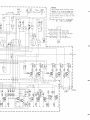
I
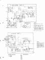
A2 LOG|C
(NoTES
1-6
)
to-l
139-3
z
I
REcoRo
,
-l
ns-z
e
{--------'-
t\
I"I,*
I
J31-L
I
\
I
wtN0
STOP
d
-
301
fo.e
el
,-l
l.,u-,
t0
REMoTE
I
c0NTROLI
J8_l
'T=
I
302
I
t-ty
u(05
t3
\
12
-
o308
BC
ra7
I
pq-r
I-,-
orfi"ol
:
L
PART OF AI
(MOTOR
CONTROL)

lP s7a
Ms2 REcoRD
2 b--1'
J38-3\J9-23C1
-L\J_AJ-
P5-8
5
rl
rO
REMOTE
CONTROL
RECOFO
P
RE SET
M.S.4
MEMORY
COUNTER REWIND
)'*<31:LJ I
s'"
.L'
NOTES:
l.
uHrEss
oTHERwrsE spEcrFrEo RESrsraNcE
rN oHMS.
2.
aouro*t"r
No's 30r-399
ARE
oN
AssEMaLy
rtAu.
COMPONENT NO,S
I.OI-199
ARE
ON
ASSEMBLY
2(A2).
3.
sn ,raras
aRE sHcw*
rN
THE
powER
oFF
posrtoN.
4.
uNrrss
oTHERwrs€ spEcrFrEo ALL orooEs aRE
1N1r(8
5.
*
,,o*
oEr{oTEs
+
r3.5v.
6.
"atwerr
wTB
aNo wTg. lov-.v
rN REwrNo
MoDE
,
wT I I
,,
WIm,
,,
lN WINO ti{OOE
//
wT
1t
4
wTlO.
?.2v
tN
PLAY MODE
(REO)
REWINO
LAMP
I
ro*orort
w'*o
IBLACK) GROUND
|
'"'i'.:"'Jfi:lJ;
l-*'"l'"'#,i'Hilr
I
I
I
0
311
8C15?
RECORD
I
BLACX
)
RECORO
I
PURPLE
I
REC.LAMP
iDARX OREEN)
+l8V
(
GREY
)
PLAY
(WHITE
I
PLAY
LAMP
{YELLOW)
REMOIE
CON]ROL
SOCX
E
T
-l
I
I
>ro
J9-r
I
I
I
I
I
I
I
I
I
I
I
tl
lr
rlo
)s1-2
OSCILLATOR
0315
BC\t7
_t
(l
AI
:L
I
ilsl
,l
o
309
BC 117
o 3lr
ac
111
o312
8C685
o3r3
BC 185
/^t

ffiffi
H
o
,lF'
^ (
cRi.01
I
I,,,
csoT
I
nt
PI6_l
.-:
(Pl6-3)
NOTES:
I
I.UNLESS
OTHERWISE
SPECIFITD
RES,STANCE
IN
ONMS,
2.prrc
renv,"ar
No,s
FoR
THE
R-CHANNEL
ARE
GIVEN
IN
BRACKETS
EESIOE
IHE
L-CHANNEL
PLUG
TERMINAL
NO'S.
3.,-anor"r,
HAS 50r-sr0,
aND
R-cHaNNEL
HAS
601-610
as
coMPot{ENT
NO.9.
WHEN
REFERING
TO
R-CIANNET
COMPONENT
ADO
IOO
TO
THE
L-CHANNET
NO'S
{E.G
R5OI
OF
THE
L.CHANNEL
HAs IHE
SAME
VALUE
A5 R
60I
OF THE
R-CHANNEL
)
A2
LOGIC
BO
r
I
I
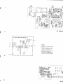
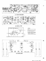
43
MIC/LINE
AMP
(NOTES
I-3)
tr.sv
3!99
I
->
+13.s
v
PHONO
RA
DIO
MIC
o503
8C I47B
GROUND
..
J 1L-1
- L_
I
r OCll F
rl-Fr|rli,+:t*'1oo@
[
I
I
I
sel*iszP|rg.P
:
;
T
'{l-HHFnnqrd
Hfl"ffifffiEffi'
:
1""'*:
l$l*
ffi*u:ff"ffi'xi'
+'f
l
#er
rtirri
'1'
#o-el Gl iri,,9,,?,,ill'.T
'|s
z,
_.....r + E.e
gj
ltlt,ut,lIitIIIIllllll
r'\
A3
oU]
^

\
Ra *
p@F
q?
lll I
III
I
ttl .r
d
I5l;
P
II
bal+
x Il.
-l'
=l
'ps
r
?????
aaaaa
Lk-s{--------t x .
ib2
1l.r..lr
rE
L
l&gArt#h
I..Tt I t+
J
I
-6'
oi'i
$"
laaaaaaa
E
*'.o;l;-;-!'
Jda-l
)aaaraaa:l:?-t_
? s^ 1$11"T
",
I i ITJ
tlrr
i
f
Ia-
+
13.5
V
C
BOARD
NOTES:
LuH,gss or*enwtsE
spEcrFlED
RESTsTANcE
IN
OHMS
2.pruc re*utHa,
No's FoR
THE R-cHANNEL
ARE GIVEN IN
BRACKETS BESIDE
THE
T-CHANNfL PTLG TERMINAL
NO,S
3.,-cna**Et
HAs 5ir
-599, aND R-CHANNEL
HAS 6JI-
699 AS COMPONENT
NO'S
WHEN REFERING
TO R-CHANNEL
COMPONENT
ADD IOO TO THE
L-CHANNEL NO'S
(E,G,
RSII
OF THE
L-CHANNEL HAS
THE
SAME
VALUE AS
R6II OF THE
S.CHANNEL
)
o 5r3
8C518
B
o5l1
BC5588
|
{Pr2-31
I
I
I
J,,,.,
1N 4ta8
0 511
adiiee
6v
::9
\3 OUTPUT
MIC/LINE AMP.

t---
lo'
I
INTEGRATED CIRCUIT
SIGNETICS NE 5458
0 902
BC
l17A
I
fo.rr fo.iir
L
utless
oTHERwrsE spEcrFrED REsTsTANcE
IN OHMS,
2,
"ruc
renvt*ot-
No's
FoR THE
R-cFIaNNEL
ARE GIVEN IN
BRAC{ETS
BESIOE
THE
L-CHANNEL PLUG
TERMINAL
NO'S.
3.
r-cHlrNel HAS 90r
-
999,
AND R-cHANNEL
HAS 1OOI.1O99
AS
COMPONENT
NO'S.
WHEN REFERING
TO R-CHANNEL
COMPONENT
AOO IOO TO THE L'CHANNEL NO,S.
IE.G.
R90] OF
THE
L-CHANNEL HAS THE
SAME VALUE AS
R1OOJ OF
THE
R
CHANNEL.)
4. nsor=z.z^, csor
:
rsD
6rvEs
a ?5-25'
OOLBY
FM
COMPENSATOR
R907
=3.9X,
C903=12n
0lvES
o"50-2s' DOLBY
FM COMPENSATOR
I
I
I
I
I
I
I
J
I
onfiro
I
rii6-6r
L
r
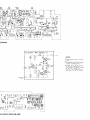
DOLBY N.R.
OFF NORMAT
lo*FM
s2B S3A
I
ii.,,,,
J
|
3-
?3
1
I
I
I
I S8A
1 SSBJ
iil
-tr1
I
I
P20-l I
I
DOLBY ENCODER
(
NOTES
I-5)
l-
-
-
ueor ooLBY B-TYPE
-
I
-:sn
T
.I
-l
i;l
-ll
I
t
l:,-; l',
FTLTER
l;
tl
|
"'i.{
PART
oF 43
I I
panr
oF Ar
I
11002 JLg
L90l
A5 DOLBY
ENCODER

-
-l
P]},-71
lJ--;;;;-)'
outeut
,
tPti-il)l
I
I
I
"zr-e
I
46 EOUAL. PLAYBACK
AMP
(NOTES
I
-3
)
I
I
riii-ir
NOTES:
l.
ulcrs
or"an*,sE sPEcrFrED
RESISTANCE IN OHMS.
2.eruo
renu,*1, xo's ron
THE R-CHANNEL
ARE GIVEN
IN
BRACKETS
BESIOE THE
L.CHANNEL
PLUO IERMINAL
NO,S.
3.1-axaxnel
HAs,or-1r99,
ANO R.CHANNEL HAS
1201-1299
AS
COMPONENI
NO'S. WHEN REFERINO
IO
R.CHANNEL
COMPONENT
AOO IOO TO IHE L-CHANNEL
N0's.
(E.G.
RIlOI OF THE
L.CIIANNEL HAS THE SAME
VALUE AS R12OI OF THE
R-CHANNEL.I
I
J51
L
I
-J
ag
TAP
E
d5
-6
,o,
I
I
SISIANCE
-CI]ANNET
IANNEL
OMPONENT
IAS THE
R CHANNEL.I
o lt02
BC 119 C
LPAT
gF
33J
t?????
atatat
? Ji'i%'
rlg
'
HYT
.H'
t
.ttf'
'
FH
t's
I
Etrl
dlFI
?'
t''$
TT
A6 EOUALPLAYBACKAMP.

-
-
REC. HEAO
L.CH.
I .,_,
+ t3.5V<--:-::+
I
--'.--
TO U tlot I
'-
1--
l
ur3or
ooLBY B-TYPE
| |
U'l3Ol
oOLBY 8-TYPE
| |
INTEGRATEO
CIRCUIT
I
'
t:
stGNETtcF sE s45B
I
I
l;ru,,.,
11
tl
|
'E
rltl
tl
''"u'
*iElr-"li
-,El
-
-l.
-rTr.f-,T-l
I
I lji'i-.I I l\#'fr-l-l
\ffi/J
Ei'il1
.J l-:tr.l
I
:l:,.,.
FH
+;T +:i:,
I
I
i;;;
fr:'"
jF
|
:fl:H_ii11
'..
f,;;,.,.
t--
I
Az
DoLBY DEcoDER
(NoTEs
l-4)
I
l,uo-,
zFs6
pfil'"''"I
sll',fi
=|;ll
I
3t+
|
d-
*T
| | ilt I
*-r
cRrPs
r
L-,o
",.0,
r
*"1 hr lnu I
u'o,ii'olffi
fro"',,02
I t-
-
-ev-v
."'*"1
|
ouTPUTl
|
-
i'i.',111
; I I
l-paTi
oF
A3I
NoTES
:
Lllq I : I I f
poLBy
N.R.
I
1.
uNLEss oTHERwrsE
spEcrFrED REsTsTANcE
..t1
| | I
|
*
|
rNoHMS.
$i?;"
| : | | ,l;::;,
l,lli-:,
oN
|
2.
'LUG
TERMTNAL No,s
FoR THE
R-.HANNEL
d
| |
LJ::::-i';:::-:
o.
I
ARE
GIVEN
lN BRACKETS BESIDE
THE
cl3l6-l-
|
I
'
-l
L-J
s
s2B(A)
r
L-CHANNEL
PLUG TERMTNAL
No's.
"-"*r"-|j-',
3.
,-c*o"*er HAs t301
-r399,
AND R-.HANNEL
HAS I101
-
I199
AS COMPONENT NO,S.
WHEN REFERING TO R.CHANNEL
COMPONENT
ADO
1OO TO
'HE
L.CHANN€L
NO,S.
IE.G.
R13O] OF THE L-CHANNEL
HAS THE
SAME
VALUE AS
RI40] OF
THE R-CHANNEL,)
/r.
psr-r,
ouv
!]gr
rN wrND-REwlNo.
r
- -
*-o*r*to*
(NoTEs
r-4)
- -l
B|AS 05C
o r507
ac la7 B
cRt5o1
zFs
i
I
I
r5o2
|
NOTES:
l. urress
or"enw'se spEcrFrED REsTsTANcE
IN OHMS.
2.
"rro
runu,no, No's FoR THE R-CHANNEL
ARE GIVEN IN MACXETS
AESIO€ TBE
L.CUNNEL
PLUG IERMIN4 NO,S.
3.
,-""on"a, HAs
r5or-r599,aNo R-CHATNEL
HAS 160I-I699 AS COMPONENI NO,S.
WHEN REF€RINO
!O R.CHAXEL COMPONENI
AOO
IOO IO IHE !-CHANNEL NO'5.
iE,G.RI5OI
OF
IHL
L-CHANNEL
HAS
IHF
SAM€ VAUE AS R]6OI OF
THE R-CHAINEL.)
4. onrv
row IEVEL
(BELow
rsv) oN J57-2
IN RECORO.
or501
BC l47B
AZIMUTH CAL. OSC
J-
IT
EI
lo
ol
ln
nl
lo
ol
[l
t
THE AZIMUTH CAL. SWITCH ARE
SEEN FROM
THE FRONT SIDE.
A
T--=-E-l
"
"1.;.;
I
r
23
a56
THE TAPE SWITC}I ARE
SEEN FROM
SOLDER SIDE
^

FIE
*$#
rE
I
a
a
t?
+l
l
-T:
lg
+t!
-L0
T
frr
gr
Ps
rLE
Tp.
ffi*"Hffir#+
cRt305
cRl306r
cl3l6
q
ol30?
6'
Eft
-E
a
I
I
L
I
IT
c1308 er30l
+++
cl36 cRr301 $311
A7 DOLBY
DECODER
A8 OSCILLATOR
lTs-
ilrT;F
-a
l,l-p.-r-n
or-r rd
i-
t
- - -
-
- -
I
|,..-.
c.,zor
'^rrt-;6u;;-l
ll-
o1702
]11 B
t
"'"
"'z
I
I
fc'rot
NOTES:
l.
urrrss otreawrst
spEcrFrED RESTsTANcE
IN OHMS.
2-eaue
ten"'"aa No s
FoR THE R-CHANNEL
ARE GIVEN
IN BRAChETS EESIDF
THE
L.CHANNEL
PLUG TERMINAL
NO'S
3.r-aHaruer
HAs r?or-1799,aND
R-cHANNEL
HAS
ISOI 1899 AS COMPONENI NO's.
WHEN
REFERING TO R.CHANNEL
COMPONENI
AOO
IOO TO THE L-CHANNEL
NO's.
{E
G RITO]
OF IHE L-CHANNEL
HAS THE
SAME VALUE
AS RI8OI OF THE
R-CHANNEL)
-
c1703
41v
^
fH.Hr
l+Etr
|
.'1"
g
fi1
lf"$BfE
&E?+5
t-t ol
,tit'
l8r
3t
l1
ll
fllTI
I lt
llll
11
ll
hfl
llll
;Bqf''o'E
J6a
P19
l..l 15
1l
2L_11
1......1 ,"Cl?01
---_--.jUl_
o,16,
S
*1[9'to'
-f
H
*-.Fi'I:F-
*-@l-*
--@F
oruoz
p
-Ogroz
.--@*-
iF'o'
'--nmF-
*-nmN--
POW€R
[-'T]o*oo..l-nl |i_}
1658-9
-78
Part No.714092
-
-
 1
1
-
 2
2
-
 3
3
-
 4
4
-
 5
5
-
 6
6
-
 7
7
-
 8
8
-
 9
9
-
 10
10
-
 11
11
-
 12
12
-
 13
13
-
 14
14
-
 15
15
-
 16
16


TANDBERG TCD 340A Alignment Instructions
- Tipo
- Alignment Instructions
in altre lingue
- English: TANDBERG TCD 340A
Altri documenti
-
Carson 510000286 Istruzioni per l'uso
-
Revox b77 Manuale del proprietario
-
Sony TC-D6C Manuale utente
-
Yamaha K-1020 Manuale del proprietario
-
-
-
-
-
Crown IC-150 Manuale utente
-
Fostex G16S-G24S Manuale del proprietario